Proceedings of the 1999 IEEE
International Conference on Robotics & Automation Detroit, Michigan May 1999
A New Adaptive Fuzzy Hybrid Force/Position Control for Intelligent
Robot Deburring
Feng-Yih Hsu’ and Li-Chen
F i 1 ’ 9 ~Dept. of Electrical Engineering1
Dept. of Computer Science & Information Engineering2
National Taiwan University, Taipei, Taiwan, R.O.C.
Abstract
The major control problems for robot debuning mainly arise from uncertainty of the robot manipu- lators and complex deburring process. In this pa- per, a new design of hybrid force/position control of robot manipulators via adaptive fuzzy approach is pro-
posed to solve these problems. The control archi-
tecture consists of an outer-loop command generator which can automatically determine the desired robot motion profile and an inner-loop adaptive fuzzy hybrid force/position controller which can realtime achieve
the command. To demonstrate the effectiveness of
the present work, it is applied to the control of a five
degree-of-freedom (DOF) articulated robot manipula-
tor for deburring tasks. 1 Introduction
Applying automated robot manipulators to replace manual deburring operation has become more and more important owing to the high cost of deburring, for some of a variety of cast parts which sometimes amounts to 35 percent of total part’s cost [I]. In gen- eral, deburring tasks are meant to remove burrs from part’s edges and to maintain the final geometry of de- burred part’s edges within some allowable tolerances.
To achieve that, a cutting tool with fixed spindle speed has to chamfer the part edges while undergoing com- pliant contour-following motion. When driving the cutting tool to perform a deburring task, the debur- ring robots have to implement two major motions: one is to apply suitable chamfering force to the part’s edge so as to remove burrs and to avoid damageto the part, and the other is to perform a contour-following motion to assure that the cutting tool will continue to contact all burrs that spread out over the chamfer.
With an aim to achieving this goal, a heuristic strategy that is often applied by experienced engineers is to control the feedrate of the cutting tool to attain the desired chamfering force. This heuristic is simply
slowing down the feedrate of the cutting tool when the encountered burr is large, but speeding it up if other-
wise [l], [4].On the other hand, the chamfering force for a constant feedrate and a specific chamfer depth is proportional t o the cross sectional area of the burr [2], which motivates us to command the feedrate of the cutting tool so as to control the chamfering force. Hu- man operators, however, can not manipulate the cut- ting tool so precisely to produce the desired chamfer depth as a deburring robot can. Alternatively, some force control schemes such as impedance control, hy- brid force control, and other force control schemes had been applied to compliantly yield a desired chamfer depth [3]-[9]. The common feature of these approaches is to construct a model of the contact force that de- scribes the relationship between the position of the cutting tool and the magnitude of the contact force. However, it is fairly hard to construct a precise model
and as a result a deburring scheme based on a human-
skill model was proposed [4]. Furthermore, a neural network controller which is equipped with the ability of refining the deburring behavior by learning from the skillful engineers was also developed to solve this problem [5].
To
sum up, to achieve automated deburring, the guideline for human operator in performing the de- burring task needs to be incorporated into the con- troller and the self-tuning capability needs to be en- dowed so as to adaptively correct the control law for coping with uncertainties in deburring dynamics. On the other hand,the fuzzy variable structure control can provide the stability and smoothness at the same time of a fuzzy control if the fuzzy control is formulated in a form of variable structure control [17]-[19], or if a vari- able structure control is augmented with some rule- parameter setting mechanism [20]-[23]. In this paper, we present an adaptive fuzzy hybrid force/position controller via variable structure control approach ton
Figure 1: The deburring robot performing the
contour-following task
achieve the aforementioned goal in this paper.
2 Dynamic Model of a Deburring Robot in Cartesian Frame
Consider an n degree-of-freedom articulated debur- ring robot whose cutting tool to is commanded to perform contour-following motion in order to remove burrs from a part, as depicted in Fig. 1. Its dynamic
model in joint coordinates can be derived as follows:
(1)
where q E
Rn
is the joint vector, M ( q ) ERnxn
is the inertia matrix, C(q, q ) q is the vector representing the centrifugal and Coriolis forces satisfying M-
2C is a skew-symmetric matrix, G(q) is the vector of gravita- tional forces, D ( q ) is the vector of friction forces, ~fis the vector of cutting forces and moments, and r is
the vector of control input forces and moments. To ease the controller design for the deburring task, we re-express the dynamic model in the Cartesians co- ordinates. First, we assume that the Cartesians coor- dinate of the cutting tool, namely,
x,
is with respect to the world frame{W},
so thatx
can be representedas a function of its joint coordinates, q in the reference frame, i.e.,
where
x
= [ x I , . - . , z ~ ] ~ = [X;,X:]~, withxp
ER3
being its position vector of cutting tool andxo
ER3
being the orientation vector, and q = [ q l , .
.
.
,
qnIT.Differentiating equation ( 2 ) , we then get
h.i(q)ii
+
C(q,Q)Q
+
G ( q )+
O ( Q ) =+
T f ,x
= H(d, ( 2 )(3)
where J ( q ) E is a Jocabin transform matrix and
is assumed to be of full rank for q lying in a compact set in the joint space, so that there exists a one-to-one mapping between
x
and q in a properly defined com- pact set [ll]. Thus, J has a sudo-inverse matrix J+,satisfying J J + = I. Then, letting M , = J + T M J f , J+TD, fT = J + T ~ and
f
= J + T ~ f , we can derive thedynamics of the robot manipulator in the world frame
as follows:
Mx(x)Z
+
C,(x,k)k
+
G,(x)
+
D,(k) = fT+
f,
(4)Here, the torque vector I- in joint coordinates can be derived as r = J T fT. To simplify the underlying con-
trol problem, we will assume that the cutting tool is in contact with the part only at a single point so that the moment exerted by the cutting tool equals zero. Therefore, the cutting force/moment, f , can be de- noted as
f
= [f:+
f:, O,O, 0IT, where fn E R3 is the vector of contact force perpendicular to the chamfer surface of the part, and ft ER3
is the vector of the chamfering force tangential to the chamfer contour of the part.Now, we need to derive the dynamics of the cham- fering force and the contact force during the debur- ring process. Let
xs
represent the vector of the cut- ting tool position on the art's edge when the chamfer depth is zero (see Fig. 27, namely,x,
is subject to a constraint equation$(xs)
= 0. To express fn andft
on the chamfer surface, we define two unit orthogonal vectors, n 1 and 122. The former is opposite to the di- rection of the contact force and can be constructed as
n1 =
ai,
where V represents a gradient opera-tor. However nl can not be constructed directly from the above equation since
x,
is not measurable. There- fore, we approximate n1 by n 1,:.;$/,
,
when the chamfer depth, say, 6 E % I , very small, where
xp
is defined to be the position of the cutting tool, which is attributed to the fact thatV$(xp)
xV$(x,)
0. On the other hand, n2 is defined to be opposite tothe direction of contour-following motion on a cham- fer with zero depth, satisfying n1 I n2, then it can be
expressed as
c,
= J + ~ C J +-
J + ~ M J + J J + , G , = J + ~ G , D , =As a result, we can rewrite the contact force and the chamfering force, respectively, as f n = -Ilfnlinl
and f t = -liftllnz. Furthermore, it is shown that the magnitude of ft is found to satisfy the following [4]:
llftll = g l n T ~ p 1
+
M - k P I+
Ptlh= gIl(1- n ~ n T ) k p l l + hlnfxpl
+
pi,,, (6)where g and h are coefficients which vary with dif- ferent burrs and chamfer depth, and Pih is a constant value representing the threshold ower of the cutting tool. However, it is very much diicult to establish an exact model for the contact force. Here, we assume that the deburring robot is rigid enough and the spin- dle of the cuttin tool rotates at fast speed, so that the magnitude o f t h e contact force will roughly obey the following relations:
Inner-Loop Controller Outer-Loop Command Generator , _ _ _ _ _ _ _ _ _ _ _ _ _ _ - _ - _ _ _ _ _ n
.
-: r Burrsf"
Deburred Part Edges
Figure 2: The geometry of part edges durring the de- burring process
where is a threshold as the cutting tool contacts
the chamfer, c1 is the stiffness of the part, and c2 is the damping ratio of the cutting tool moving into the chamfer.
3 Control Architecture of the Deburring
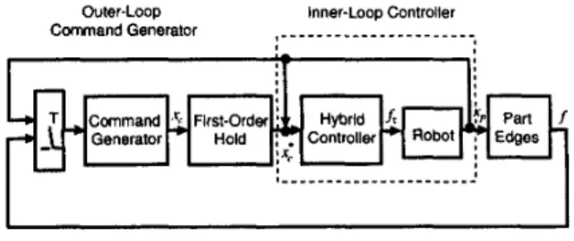
Thus far, we have derived the dynamics of the robot which performs deburring operation. To accomplish the deburring task, a well designed controller to drive the robot system is needed. Here, the proposed con- trol architecture consists of an outer-loop command generator and an inner-loop controller, as depicted in Fig. 3. The former determines a positional profile
command such that the desired chamfering force and contour-following motion can be realizable, whereas the latter aims at driving the robot to execute that command in a compliant manner so as to yield a de- sired chamfer depth. Generally speaking, since the servo-rate of the inner-loop controller is much faster than that of the outer-loop command generator, we as-
sume that the outer-loop has a nonzero servo-period
T whereas the inner-loop controller is considered as a
continuous type for simplicity, i.e. its servo-period is
zero. The motion commands which are not so much
time critical from the viewpoint of the inner-loop con- troller, like the chamfering force and the locus of the contour-following motion, are handled in the outer- loop. The positional command from the command generator is then transferred to a continuous input via passing through a first-order hold mechanism for the inner-loop controller.
Robot
.
L
T Command .', First-OrderL*
Generator*
HoldFigure 3: The control architeture of the deburring
robot
3.1 Outer-Loop Command Generator
The function of the outer-loop command generator is mainly t o ask the inner-loop controller to control the attached cutting tool to produce a desired positional profile. Hence, our goal here is t o design such a desired position command, whereby the following objectives can be simultaneously realized provided the cutting tool can implement the command.
0 maintaining a desired constant chamfering force
0 performing a contour-following motion
First, simplifying the model of the chamfering force
as in equation ( 6 ) , we consider the case where the cut- ting tool velocity in the direction of n1 is much smaller
than that in the direction of n2, i.e., Inrip[
<<
lnTkp1. As much, we let llftll tend to a constant
llftdll by letting the cutting tool position x p follow a desired positional profile command xc during the sampled-period, expressed as follows:
where T is the servo-period of the outer loop, IC = 1 , 2 , . - . ; 210 is the default feedrate, set to prevent x p
from changing too fast to damage the part as
11
ft1)
- Pih becomes excessively small, where v,>
0 is its offset. Clearly, when k p+
2 c ( k T ) - 2 c ( k T - T ) T , we can get a result that llftll closely approximatesI l f t d l l .
Finally, passing z , ( k T ) through a modified first- order hold filter to the inner-loop controller, we can get a continuous desired position trajectory x:(t) with
an initial value xF(O) = xc(0) as follows:
z , ( k T ) - z,*(kT - T )
3.2 Inner-Loop Hybrid Force/Position Controller
The inner-loop controller is to drive the robot t o perform the aforementioned positional profile com- mand in a compliant manner so as t o yield a desired chamfer depth. Since the direction for measure of the desired chamfer depth is perpendicular to that of the contour-following motion, we can apply a hybrid force/position control to achieve the above oal.
In order to obtain the desired chamfer fepth, de- noted as 6:, under the desired contact force, denoted as f n d , the desired positional trajectory of the cutting tool 6 d ( t ) , in the direction of the chamfer depth, i.e.,
n1 needs to be carefully selected. Apparently, & ( t )
is related to the contact force f n , and it will eventu- ally approach the desired chamfer depth 6: provided the contact force approaches the desired one. To con- struct Sd(t), first we let the magnitude of desired con- tact force f n d be defined as follows:
l l f n d l l = (c16:
+
CO) (9)Then, & ( t ) is defined such that its initial condition
&(O) = 0 and its time derivative is given in the fol- lowing:
'
hd = k6(llfndll - Ilfnll) = k6 [ - c 2 &
+
C l ( 6 : - 611= b e f , (10)
where kd
>
0 and e f =11
f n d l l
-
llfnll
is defined as the current error of the contact force. Note that, when8
-b8,
and 6 -b&,
we can rewrite the above equation as(11)
which implies that 6d approaches 6: exponentially and, hence, the error of the contact force, e f t can ap- proach zero.
Given x , * ( t ) and 6d, we can augment the contour-
following position command by summin the de-
sired chamfer depth trajectory 6 d n l and t i e desired
contour-following profile trajectory x,* together. Thus, an augmented desired position trajectory, x p d , can be expressed as
(1
+
kJC2)h,j+
kJC16d = k 6 C l 6 : ,Z p , j ( t ) = z:(t) + a d ( t b l , (12)
from which we now define the position trackin error
as e p ( t ) = x p d
-
x p . Similarly, we let the jesired orientation of the cutting tool be given as X O d so thatthe collective position/orientation trajectory can be denoted as xd = [ x , ~ , ~ , ~ ] ' . By this definition, we now define the vector of tracking position/orientation tracking error vector as e ( t ) = Z d ( t ) - x ( t ) = [e;, where e , = X o d - x o , which facilitates us to rewrite the dynamic model of the manipulators system (4) as follows:
Mz(G)E = MzXd
+
Cz(G,k)k+
Gz(Z)+
D z ( k ) - i r - f, (13)Clearly, our objective is now transferred to the de- sign of a control law f T that can drive e to zero so that
the desired (constant) chamfering force f t d and the desired (constant) chamfer depth 6: can be achieved
simultaneously. To that end, we define a sliding vari- able vector s =
+
Xe, where X E !R6x6 is a diagonal positive definite matrix, and re-express the above dy- namic model (13) as follows:M z S
+
( K+
Cz)S = M z ( z d+
Ae)+
Gx+
Dx+
Cz ( k d+
h)+
KS - f - f r , (14)for some diagonal positive matrix K E
PX6.
Appar- ently, if the controller design can force the right hand side (RHS) of the equation (14) t o be zero, then the resulting system will be subject t o the closed-loop dy- namics M,S+
( K+
CZ)s
= 0, which not only assures the stability of the system, but also guarantees the exponential convergence of the tracking error e . As aresult, an ideal control law can be designed as
f:
= M Z : ( s d+
A&) $. Gx+
Dz+
C z ( x d+
xe)+
KS - f (15)However, it is difficult to implement this ideal con- troller due t o various kinds of model uncertainty and, hence, the major control problem here is how t o real- ize such an ideal controller.
4 Control Algorithm
As has been mentioned, the parameters associated with contact force, CO, c1 and c2 are often estimated
as
6 ,
21, and Ez, respectively. These estimate valueswill result in the estimate of the desired contact force apart from the true desired one, and will be referred to as the virtual desired force in contrast with the actual desired one. Denote this virtual desired contact force,
f n d , whose magnitude can be expressed as
h
Ilgdll
= &
(16)h
Apparently, here our goal is to let llfndll approach
l l f n d l l so that 6d(CxI) = 6;. To achieve this goal, we build a virtual contact force f n and express its mag- nitude as
(17)
whereby the error between
I(
frill and Ilxll
can be de- rived as follows:IlKIl =
&
+&;s+a,
A
en =
IIjnII
-IIjnII
+ G b + G d . ,
(18)where G = q,
-
6,
Z1 = c1-
21 and E2 = cz-
Ez.To reduce this error, we update the parameters by the following update law:
(19)
h h A .
CO = re,; ci = r6en; c 2 = rben,
Consider the robust controller as following:
f r = K s -
f
+
ff(ll~ll, s)H = for some r
>
0.( 6 1
+
b z l l ~ l l+
b3l1~Il2)sgn(s)+
(b4+
bsllzll)s,(20) where b l ,. . -,
and b5 are some constants. Then, the following theorem is valid.Theorem 4.1 If the control law is given as in (20),
then the tracking error e will be driven to zero expo- nentially in term t .
Figure 4: The m-order B-spline basis for m=O, 1, 2,
and 3
4.1 Adaptive Fuzzy Hybrid Control
Howecer, gain parameters b l ,
.
. . ,
bs of H(llzl 5 ) .an adaptive fuzzy control algorithm as our control so- lution. Let the actual control law fT be rewritten as
follows:
f r K s - f
+
fs(ll4l7 31, (21)where
Ks
is a linear PD type compensator andf,,
is the key adaptive fuzzy compensator. Here, our goal is to design a fuzzy controller uf = [ufl,.
,
ufnIT = f,,which can compensate for the uncertainties. Then, consider a fuzzy controller uf, consisting of n ( n =
6 ) two-input single-output (MISO) fuzzy controllers,
which are respectively characterized by
are very difficult to be obtained. Here, we intro
k
uceA
U f , = U f i ( I l ” l l , S i )
=
U f a ( Y 0 , Y i ) : 0 0 x Ra + 92where u f i is the i-th fuzzy controller, y
=
[ Y O , 3 1 , ..
,
y,IT =[bll,
S S ,-
,
and 11x11 and si(i.e., 30 and y i ) are the i-th input fuzzy variables,
00 3 [-YAo,TAo],
...,
$2, s [-YA,,,YA,,] withY
being a positive integer and can be set arbitrarily large to constitute enlarge enough compact sets, andA,, .
.
. ,
A,, being some positive real numbers. Here, each of the membership functions is given as an m- th order multiple dimension central B-spline function as depicted in Fig.4), of which the k-th dimension is6
efined as follows:1 =o
where we use the notation
z+ := maz(0, d ) (23)
The m-th order B-spline type of membership function has the following properties:
0 an (rn
-
1)-th order continuously differentiablefunction, i.e., N m k ( Y k ) E Cm-l;
0 symmetric with respect to the center point (zero
point)
Cg-,
E,”=-,
NmO(Y0 -‘&)Nmk(Yk - j A k ) = 1, for IC E Z+Then the membership functions for the k-th fuzzy
(24)
variable Y k are defined as follows:
P k i ( Y k ) = N m k ( Y k
-
iA&)whose compact support is given as:
for
k
= O , - - - , n , and i =-Y,-..,O,-.-,’r,
which means that yk E znt($2ki) implies that &(&)>
0 and $2k E Ui,={-r ,..., r } S 2 k i . Apparently, it is possiblethat R k i
n
f l k j#
0 ,
for some i#
j, i.e., y k can simul- taneously fall into several compact supports. From 15, we can represent the above fuzzy controllers as loll-ow s:EE-r
xT=-r
P O i ( y O ) L ’ k j ( Y k ) e k ( i j )EE-r
xT=-T
L ’ O i b O ) L ’ k j ( Y k ) u f k =where
kf
(1141,s~2
l ~ ( l l ~ l l , S > L ~ s ( I l 4 L ~ )
=[ k s l , . - . , k s n l T is a smooth function vector to make uf smooth, and [ - A , , Ak] is regarded as a designated dead-zone range which can be arbitrarily set.
Then the following adaptive law to update the pa- rameters vector 6k will be necessary so that the track- ing error can be driven toward the dead-zone range:
e k ( i j ) = r ’ k ( i j ) ( Y O r Y k ) Y A k , for Yk E f l k (29)
where T
>
0 is some positive constant.Finally, we design fT as
Figure 5: The tracking error of normal contact force
where d i a g ( z ) s g n ( s )
>
d i a g ( H ) s g n ( s ) , and the t-th element ofC
ER6
is defined as follows:(31)
1, a ? l k E n k ;
(k =
{
0, otherwise.Then, the following theorem states the condition under which the above-mentioned adaptive fuzzy con- trol law will yield satisfactory result.
Theorem 4.2 If the update law and the control law are given as in equations (29) and (30), then the track-
ing errors wall asymptotically converge to a neighbor-
hood of zero.
5 Experimental Results
A five degree-of-freedom (DOF) articulated debur- ring robot arm equipped with a Zebra force sensor and a cutting tool is set up in the Intelligent Robot Lab- oratory of Dept. of Computer Science & Information Engineering in National Taiwan University. The ex- periment is performed by controlling the robot arm to drive its cutting tool to chamfer the edge of the cylin- der part which has a 30mm.radius for cross section. The control architecture based on an industrial
PC
(80486 dx2-66 CPU) has 2.5
ms
sampling-period forthe inner loop hybrid controller and 25 ms sampling period for the outer loop command generator. The desired contact force and the desired chamfering force are set to 5 N t and 10 Nt, respectively. The number of fuzzy rules is set to equal 6 x
(2Y
+
1)2 = 6 x 9 x 9.At the beginning, since initial parameters in matrix 0
are set to zeros, which is similar to only use the PD controller to compensate for the uncertainties in the first period of deburring motion after the first period the force error is quickly driven toward zero as Fig. 5 .
6 Conclusions
We had proposed an adaptive fuzzy hybrid force/position controller, which can update fuzzy rules to compensate for the robot dynamics along with the
force dynamics induced by the contact between the cutting tool and the part’s edge an4 identify the ac- tual desired contact force. Various experimental re- sults have been provided to verify the effectiveness of the developed work.
References ~~~ ~~~ ~ ~
H. Kaaemooi. J . J . K r a m e r a n d B. M.. “An approach t o A u t o m a t e d Debur- ring by Robot Manipulators.” ASME Jnurnnl of Dynamic System. Msuatrtrmrntr And Cantml. m l . 108. no.4. DEC. 1986
M. 0 . Her a n d H. Karernooi. “ A u t o m a t e d Robotic Deburring of P a r t s U d n g Compliance Control.” ASME Journol of D y n o d e Systenrr Mcusamnimtr
And Contml. vol. 11.9. M n n h . 1991
H. K a m r n o o i . “ O n t h e R o b o t C o m p l i a n t Motion Control.” ASME J n u m n l of
Dynamic Ssstenis Meammmerrta And Contml. rml. 11 1. Septenaher.. 1989
Sheng Lu a n d H. Aaada. “Transferring Manipulative Skills t o R o b o t s : Rep- reeentation a n d Acquiaition of Tool Manipulative Skills Using a Proccs. Dynamics Control.” ASME J n r n ~ d of Dynoniic Syatemn Meoswrmnents And Con-
tml. ad. 114. .luna. 1992
Sheng Lu a n d H. Asada, “Teaching a n d Learning of Deburring Robot* Using Neural Networks.” Proc. Of 1993 IEEE lnt. Conf. O n Robotic8 nnd Aa- tnmntion. pp359-.?45
G. M. Bone a n d M. A. Elbestawi ” Robotic Force for Deburring Using an Active E n d Effector.” Robotic,$. snl. 7. pp-dfl3-Dfl8. 1989
G. M. Bone. M. A . Elbeatswi. R. Lingarkar a n d 1. Liu “ Force Control for Robotic D e b u t r i n g . “ ASME , J n u m d of Dynnnrir Syrtemr Measurrmrrtr And Contml. r i d . 113. Septenrhcr. pp.995-4Ofl.1991
M. S. Ali. M. N. Noori a n d J . T u r i . “ A u t o m a t i c Deburring Utilising a Real-Time I m p e d a n c e Control Strategy.” Computer and Sttwcturr tinl. 46. no.8
pp5Gl-571. 1993
D . Jeon a n d M. Tomizuka. “Learning Hyhrid Force a n d Poeition Control of R o b o t Manipulators.” IEEE nntrswtiasr on nobnticr alnd Aatornntinn 18”. 9. no. 4 , pp. ( 2 . 9 4 7 2 . Aug. 199.9
[lo] L. X. Wang. “ S t a b l e A d a p t i v e F u s s y Control of Nonlinear S y s t e m s ” . IEEE.
C m z f . ~n D e a r i o n and Contml. 1992
Ill] J . Maraden. E l e m e n t a r y Classical Analyeis. San Franciso: W . H. Freeman.
1974
1121 J - J E. Slotine a n d W. Li. Applied N o n l i a e i r r Contml. Englewood Cliffs. NJ: P r e n t i e e Hall. p p . 2 7 8 - 2 8 4 . 1891.
1131 R. M. Sanner a n d J - J E. Slotine. “ G a u e d a n Networks for Direcet Adap- tive C o n t r o l ” , IEEE. Zhnn. on N e w d N e t w o r k s . vol. .9. no. 6. pp. 867-865. 1992. 1141 S . S a s t r y a n d M. Bodaon. Adoptitre Coatml: Stability. Currrirqencc. and Rnh,ist-
nene, P r e n t i c e Hall. 1989.
(151 L.-X. W a n g . A d a p t i v e Fussy Symtems a n d Control: Deaign a n d S t a b i l i t y analyeim,NJ:Prentice Hall. 1994
1161 V . S . C . R a v i r a j a n d P. C . Sen. “ C o m p a r a t i v e S t u d y of Proportional-
Integral .Sliding Mode. a n d Furny Logic Controllers for Power Converters.”
IEEE fin.. on lndwtrg Applzeuttotis. vol. S.9. no. 2. pp. 518-524. 1991 1171 J a c o b S . Glower a n d Jeffery Muunighan. “Designing Fu5ay Controllers
IEEE n n n a . on R n . y S y d c m r . *,nf.d. from a variable s t r u c t u r e s s t a n d p o i n t . ”
no. 1. pp.l.98-144, Feb. 1997
1181 S.-C. Lin a n d Y.-Y. Chen. ”Design of Self-Learning Fuzzy Sliding Mode
Controllers Based o n Genetic Algorithms.” Ftlrzy S e t s rind Syaterns so1.86. nr3.2. pp. 199-153. Mor. 1897
1191 J . C . Wu a n d T. S . Liu, “Fuzzy Control Stabilization with Applicationa
IEEE nrmr. on S!rrtenrr. Man. irrrd Cybntnnstm. PnrtB:
t o Motorcycle Control.”
Cybstnetici. vol. 26. no. 6. pp.856-8/7. DEC. 1996
[ 2 0 ] Feng-Yih Hau a n d Li-Chen Fu. ” A d a p t i v e R o b u s t Fuzzy Control for R o b o t Manipulators”. IEEE Cowfrwnce o n Rnbotrcr mid Aatonidisr,. pp. 629-654. 1994 (21) Feng-Yih Hau a n d Li-Chen F u . ” A New Design of A d a p t i v e Fuzzy Hy-
brid Force/Poaition Controller for R o b o t M a n i p u l a t o r s ” . IEEE C o n f m ~ n m
0.1 Robotics u n d Atitmadinn. p p . 86.9-868. 1995
(221 Feng-Yih Hsu a n d Li-Chen Fu. ” A n A d a p t i v e Fiiezy Hybrid Control for R o b o t M a n i p u l a t o r s Following C o n t o u r s o f an Uncertain O b j e c t ” . IEEE Cotrfwmrr on R n h o t i r r and Automation. p p . 225’2.2257. 1996
1231 Feng-Yih Hsu a n d Li-Chen Fin. “Intelligent Robot Deburring Using Adap-
tive Fuzzy Hybrid Control” Pine. 27th Internntmnnl Synipomtm on lndtrstrid
Robots. pp. 847-852. M i l o n . Italy. 1896
1241 Feng-Yih. Hsu a n d Li-Chen F u . “Recent Progress in F u m y Control.” A
C h a p t e r in Control P r o b l e m s in Robotics a n d A u t o m a t i o n : F u t u r e Direc- tions. E d . B r u n o Sicillinno. Springer-Verlag. London, 1997