architectures. To overcome this problem, design analysis and opti-mization of MPEG-4 shape coding are addressed in this paper. By utilizing the RISC-based model, computational behaviors of the MPEG-4 shape coding tool are carefully examined and analyzed. The characteristic of a large amount of bit-level data processing and data transfer of MPEG-4 shape coding motivates us the optimization of bit-level data operations. Applying the data-flow optimization and data reuse techniques, bit-level computation-ef-ficient architectures, such as data-dispatch-based binary-shaped motion estimation, the delay-line model, and configurable con-text-based arithmetic coding, are designed to accelerate bit-level processing. These hardware blocks are integrated and scheduled in a very efficient data flow to achieve real-time performance for MPEG-4 CPL2 specification at 23.5-MHz clock rate. The system architecture is implemented using Verilog HDL and synthesized with a 0.35- m four-layer CMOS standard library.
Index Terms—Binary motion estimation, CAE, content-based coding, MPEG-4, shape coding, VLSI.
I. INTRODUCTION
R
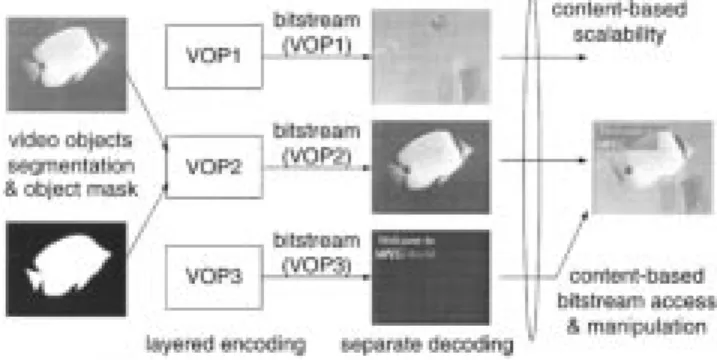
ECENT ongoing evolution of digital multimedia tech-nology directs the multimedia communication service to provide more flexible and powerful functions, such as con-tent-based interactive, error robustness, and universal access. MPEG-4 [1], [2] is undoubtedly the emerging standard for such multimedia communication trend. One of the most compelling features of MPEG-4 is the content-based functionality (see Fig. 1). It provides the powerful capability that end-users can directly access the video content (objects) rather than video frames in video scenes. Since video objects’ shape information is transmitted in addition to video texture, end-users can directly operate the video content in object-oriented manner. Thus, an efficient tool for the coding of shape information is the key technology to make the object-based functionality successful. For reference, Brady [3] presented a comprehensive review on MPEG-4 shape coding.Manuscript received December 6, 2000. This paper was recommended by Associate Editor S. Chen.
H.-C. Chang is with with AVerMedia Technologies, Inc., Taipei, Taiwan, R.O.C. and also with the Graduate Institute of Electronics Engineering, Department of Electrical Engineering, National Taiwan University, Taipei, Taiwan, R.O.C. (e-mail: [email protected]).
Y.-C. Chang, W.-M. Chao, and L.-G. Chen are with the Grad-uate Institute of Electronics Engineering, Department of Electrical Engineering, National Taiwan University, Taipei, Taiwan, R.O.C. (e-mail: [email protected]; [email protected]; [email protected]).
Y.-C. Wang is with AVerMedia Technologies, Inc., Taipei, Taiwan, R.O.C. (e-mail: [email protected]).
Publisher Item Identifier 10.1109/TCSVT.2002.803221.
Fig. 1. Object-based visual communication.
The MPEG-4 shape-coding tool mainly comprises the following coding algorithms: binary-shaped motion esti-mation/motion compensation (BME/BMC), context-based arithmetic coding (CAE) [4], [5], size conversion, mode decision, and so on. These coding techniques can be applied in various combinations to provide very efficient compression performance. Besides, better rate-distortion tradeoff for various transmission environments can also be supported by the flex-ible MPEG-4 shape coding scheme, i.e., the size-conversion mechanism. However, such a flexible and high-efficient coding tool is based on the complex decision process and high-com-putation tasks. According to previous studies [6]–[9], MPEG-4 shape coding features the high-computing and high-data-traffic properties. For example, under the Core Profile Level 2 (CPL2, maximally 23 760 MB/s) specification [1], [10], the analysis of a shape-coding tool on a generic RISC machine reveals that several groups of pictures (GOPs), both on arithmetic/control execution and memory access, are required. Our analysis also reveals similar results, and the BME/BMC, CAE, and size conversion can take up to a 95% computation load.
Several previous works [8], [11], [12] presented a few results on architecture design of MEPG-4 shape coding/decoding, but few of them reported a comprehensive design-space exploration and optimization. The contribution of this paper is the optimiza-tions for the shape coding of MPEG-4 video coding derived at both the algorithm (bit-data parallelism) and architecture (par-allel data flow optimization, data reuse) levels. In the bit-data parallelism (subword parallelism [13]) approach, several bits of data can be simultaneously processed by the same operations. To achieve this, the resulting bit-data addressing is handled by the proposed smart data-flow organization. In addition, the data reuse technique combined with data-flow optimization can re-move the bottleneck of heavy data transfer.
This paper is organized as follows. The core algorithms of MPEG-4 shape coding are briefly reviewed in Section II. In Section III, comprehensive complexity analyses for these algo-rithms are presented first. Based on these analyses, we describe
Fig. 2. Coding flow of MPEG-4 shape-coding tool.
TABLE I LISTS OFBAB TYPES[1]
the design-space exploration and optimization for real-time im-plementation of MPEG-4 shape coding in Section IV. In Sec-tion V, VLSI architecture design based on our design space ex-ploration is presented. In addition, the architecture-level opti-mization, including data-flow organization and data-reuse tech-niques, are described. Finally, we summarize our conclusions in Section VI.
II. OVERVIEW OFMPEG-4 SHAPECODING
This section briefly reviews the MPEG-4 shape-coding tool. The coding flow of MPEG-4 binary shape coding is shown in Fig. 2. Basically, this coding flow employs the block-based structure similar to the coding of texture data (YCbCr). The basic coding unit, which has the block size of 16 16 pixels, is called binary alpha block (BAB). For each BAB, the mode decision is performed first in order to determine the BAB type and its corresponding coding flow. Each BAB can be classified into one of the seven types, as listed in Table I. For the coding of transparent (type 2) and opaque (3) BABs, only the BAB type needs to be encoded. This means that only a few bits are required to transmit transparency and opaque BABs. For the coding of other BABs (also called boundary BABs), however, their con-tents should be encoded via different coding flows according to the video object plane (VOP) type and the rate-distortion deci-sion.
Basically, except for the transparent and opaque BABs, boundary BABs can be further classified into one of the Coded (4, 5, 6) and No_Update (0, 1) subtypes. The Coded
TABLE II
RUNTIMESIMULATIONRESULTS OF THEMPEG-4 SHAPEENCODING (RUNTIMEUNIT: SECONDS)
TABLE III
RUNTIMESIMULATIONRESULTS OF THEMPEG-4 SHAPEDECODING(RUNTIME UNIT: SECONDS). SIZECONVERSION OFDECODING ISEXECUTEDONLYWHEN
THE“CONV_RATIO” FIELD OF THECODEDBABISNOTEQUAL TO1
type indicates that intra-CAE or inter-CAE is required for the coding of intra-mode BABs or intermode BABs respectively, while the No_Update type only needs to transmit the motion vector information for the inter-BABs. Intra-CAE is employed to encode the boundary BABs of intra-VOP, while the boundary BABs of inter-VOP can be MC encoded by using motion vector predictors or calculating new motion vectors by BME. This MC-encoded BAB is then encoded by utilizing inter-CAE, or it can be skipped if the lossy coding mode is enabled. The boundary BABs of inter-VOP can be coded by intra-CAE if intra-CAE can provide a lower bit rate than inter-CAE for coding such BAB.
In summary, MPEG-4 shape coding requires a complex decision process and several high-computation tasks in order to select the best coding type for each BAB. These tasks, including mode decision, BME/BMC, size conversion, and intra/inter-CAE, are applied in seven types of combinations so as to produce several coding results (rate, distortion). Then, choosing the coding type is based on the user-defined rate-distortion constraints. Eventually, the coded bitstream of the best coding type is transmitted in streaming format.
III. COMPUTATIONALCOMPLEXITYANALYSIS
This section highlights the analysis of the computational complexity of MPEG-4 shape-coding algorithm. The com-putational complexity is measured by the following metrics: dynamic run-time statistics and static arithmetic/memory/con-trol operation counts. Two different approaches (simulative and analytic methods) based on the RISC-like computation model [14]–[16] are used.
A. Dynamic Run-Time Analysis
Basically, dynamic run-time analysis is performed on the basis of realistic program execution. In this approach, software implementation of the MPEG-4 shape-coding algorithm is required to perform the analysis. Momusys C implementa-tion [17] of MPEG-4 video coding is a very good reference implementation. In order to achieve a clearer result, this
Fig. 3. Kernel part (pseudo program) of the BME algorithm.
implementation is refined as follows. First, the core imple-mentation of shape-coding algorithm is rewritten. The major modifications include the data structure simplification and code replacement of some redundant parts. After that, the GNU profiling tool (i.e., gprof) is adopted to collect the run-time statistics of this implementation.
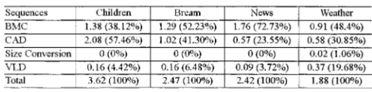
In this simulation, four sequences (children, bream, weather and news) of 100 CIF-format VOPs are tested. Tables II and III list the runtime simulation results of shape encoding and de-coding, respectively. The results reveal the heavy demand of computation power for this nonoptimized implementation of shape encoding. The performance is much less than one VOP per second, which is very far from real-time encoding speed. In order to achieve the real-time encoding performance (30 fps), BME computation, which takes nearly 90% of total computa-tion load, should be speeded up about 100 times, and other tasks should also be speeded up ten times.
A similar approach based on time-dependent instruction-level analysis model is reported in [7]. This report indicates that the coding of a P-VOP alpha plane requires a significant high-com-putational power and data transfer when the shape’s object has great changes. That means that BME is applied for the coding of many boundary BABs of current P-VOP. Their analysis re-sults also reveal that “load/store” operations play the major role in overall computation of MPEG-4 shape-coding algorithm. In other words, the optimization strategy should reduce the number of data transfer operations effectively.
B. Static Analysis
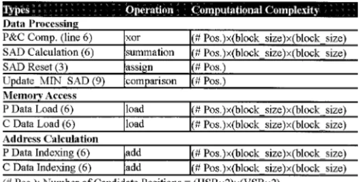
Static analysis explores the platform-independent algorithm complexity by means of the number of data processing, memory access and addressing calculation operations. We first analyze the BME algorithm as an example to illustrate the static anal-ysis. Fig. 3 shows the kernel code of BME computation. To cal-culate SAD, pixels of current BAB C(k, l) and pixel P(I, j, k, l) in the search area are compared, as shown in line 6. This com-putation contains the P&C comparison (exclusive-OR) and the SAD calculation (summation), as well as the P&C data load and addressing operations. By using this method, the complexity of the pseudo program is analyzed (see Table IV).
TABLE IV
COMPUTATIONALCOMPLEXITYANALYSISBASED ONSTATICANALYTICAL METHOD OF THEBME KERNELALGORITHMLISTED INFIG. 4
TABLE V
STATICCOMPUTATIONALCOMPLEXITYANALYSIS FOR THEMPEG-4 SHAPECODING
Assume that totally 23 760 BABs/s are coded and 30% BABs are boundary BAB. Table V summarizes the computa-tional complexity analysis for the MPEG-4 shape coding by employing the static analysis mentioned above. To achieve the real-time performance, BME computation should be greatly optimized. Both data processing and data transfer operations should be reduced to about 0.5%–1% of original operations. Section IV describes the design space exploration for the optimization of MPEG-4 shape-coding implementation to achieve such a design goal.
IV. DESIGN-SPACEEXPLORATION ANDOPTIMIZATION
A. BME
Reviewing the analysis results presented in Table II and Table V, if the BME computation can be greatly speeded up above 100 times, the real-time performance of MPEG-4 shape coding becomes easy to achieve. The SAD Calculation, P&C
(a) (b)
Fig. 4. Bit-data concatenation leads to the bit parallelism for the word-level processors. (a)n cycles required for these n-pixel data. (b) l cycles required for thesen-pixel data.
Fig. 5. Bit-addressing operations (SAP) are required to obtain the desired one row of data for some search candidate BAB in the bit-parallel optimized BME computation.
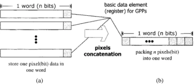
Comparison and P&C Data Transfer computations are the targets for design optimization. Since the shape information is represented in binary format (i.e., each pixel is represented in 1 bit), several pixels (bits) can be concatenated into a word and simultaneously processed by word-level operations to achieve parallel processing. Fig. 4 demonstrates the bit-data parallelism.
The size of the pixel-concatenation can be of any extent (only limited by general-purpose processors (GPPs) maximal word-length data path). The wider data path (e.g., 64-bit SIMD) can be adopted for providing more parallelism. The maximum data-level parallelism for P&C Comparison operation can be achieved if sufficient P and C data can be supplied. However, this requires data addressing to produce the required P and C data. These bit addressing operations, which include bit shifting and bit packing [in short, shift and pack (SAP)] for bit-data concatenation, result in very much computation overhead. Fig. 5 illustrates the bit-data addressing operations to be performed in the bit-parallel optimized BME algorithm. As indicated in Table VI, bit-addressing operations become a new computation bottleneck for the bit-parallel-optimized BME algorithm, though the data processing and memory-access operations are greatly reduced. To overcome this problem, the parallel architecture with a data dispatch technique based on optimized data-flow is proposed. Bit-addressing operations can be efficiently reduced by this hardwired architecture. The architecture will be presented in Section V.
B. CAE and Size Conversion
From the analysis results shown in Table II, it can be seen that CAE and size conversion do not take a large proportion of the overall computation power for the MPEG-4 shape coding.
TABLE VI
COMPUTATIONANALYSIS RESULTS OF TWO BME IMPLEMENTATIONS(UNIT: MOPS)
Fig. 6. Block diagram of the DLM.
As the bit-concatenation (parallelism) technique is adopted for the optimization of the BME algorithm, the proportion of com-putation power for CAE and size conversion greatly increases. Apparently, the bit-parallelism technique cannot effectively speed up the performance of CAE and size conversion, the major reason being that the computation nature of these two tasks is bit-serial processing. In such processing types, the input data (pixels/bits) have to be processed sample by sample, and thus, bit-data parallelism cannot provide speedup for CAE and size conversion.
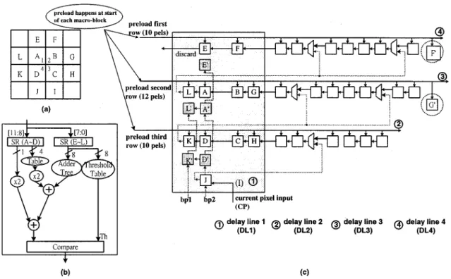
Another common nature of these two algorithms is the window-based processing, which is very common for image processing algorithms, such as 2-D filtering and morpholog-ical operations. Context generation for both CAE and size conversion (upsampling) requires such operations. In these operations, an active sample (pixel) usually needs to refer several neighboring pixels in the standard-defined template. For pixel-by-pixel processing in raster scan order, most of the reference pixels of two adjacent processings are duplicate. This leads to memory access redundancy if all reference pixels for the next active pixel are reloaded every time. Fortunately, with a few delay elements (shift registers) connected in a proper data-flow arrangement, data in these shift registers can be effectively reused, and thus the redundant data accesses can be removed. Fig. 6 shows the general form of the delay-line model (DLM) [19], [20]. Each active pixel of BAB is loaded into DLM, and flows through the shift registers array in DLM. Registers in context box are arranged such that various contexts can be achieved. By employing this model, the required context can be achieved at every cycle.
For block-based processing, the neighboring pixels to be ref-erenced may locate outside the current (active) BAB. The refer-ence region outside the current BAB is called the border region (see Fig. 7). The border region contains pixels from the previ-ously processed blocks and the unknown region, in which pixels are not yet to be processed. If pixels in the unknown region are referred, the rightmost boundary pixels (for right border) or the bottommost boundary pixels (for bottom border) of current BAB are used for reference. For handling these boundary cases,
Fig. 7. Illustration of window-based processing at the BAB boundary. The border region indicates that the pixels are outside the active BAB. Different operations are required when the template window contains pixels in the border region.
some auxiliary registers are inserted into context box, as shown in Fig. 6.
At the beginning of processing of each active BAB, pixels in the top border region are pre-loaded into delay lines. Next, all pixels of active BAB are read into the DLM via the CP, one by one. Pixels in the left border region are referred only for left boundary pixels of active BAB. Hence, they are stored in registers “L” and flow through special path. Registers “R” are added to store top-right border pixels. Similarly, only pixels in the top-right part of active BAB will refer to top-right border pixels. Therefore, after pixels in registers “R” flow into the delay line, this path to the delay line is closed, and another path from the lower delay line is selected instead.
Owing to the bit-serial processing and the window-based pro-cessing nature, it is concluded that the DLM-based dedicated hardware architecture is a very suitable candidate for CAE and size conversion (upsampling) algorithm. In fact, by employing the proposed DLM, CAE and size-conversion hardware mod-ules can be designed as cost-effective building blocks. Their ar-chitectures are presented below.
V. ARCHITECTUREDESIGN
A. BME Architecture Design
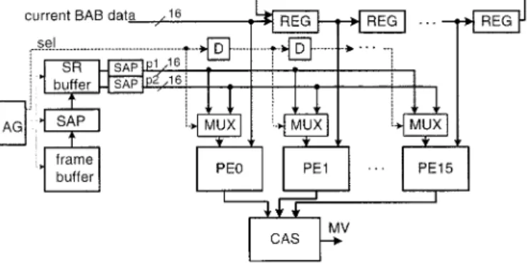
By means of dedicated hardware architecture, the com-putation of BME algorithm can be efficiently parallelized and pipelined. The BME architecture mainly comprises one processing element (PE) array composed of parallel PEs and the specified address generation unit (AGU), such that the P&C data processing and P&C data transfer operations can be efficiently accomplished. Based on the data locality and parallel processing property of the BME algorithm, the systolic PE array architecture [21], [22] is adopted as the candidate ar-chitecture. In addition, considering the adoption of the bit-data parallelism technique, the one-dimensional (1-D) array should be the best candidate for the optimization of BME computation. Fig. 8 shows the block diagram of the BME architecture. The PE array contains 16 PEs, and each calculates the SAD of one candidate BAB. The compare and select (CAS) module com-pares the SADs produced by all PEs, and then selects the candi-date BAB of minimal SAD. The search range (SR) buffer stores partial SR data that can be reused by PE array so as to reduce data transfer from the off-chip frame memory. The SAP module is required to produce the desired data since the motion vector
Fig. 8. Block diagram of the proposed BME architecture.
(a)
(b)
Fig. 9. (a) Architecture of SAD-PE. (b) Adder tree structure.
prediction units (MVPs) are not usually equal to 16, which leads to the SR not aligning the boundary of packed BAB rows. The AGU module generates address for accessing the SR buffer and control signal for SAP. The word length of the VOP memory and SR buffer is 16-bit to match the row-based processing of BME computation. Proper data flow is derived to fully main-tain utilization of processing elements in the systolic array and to reduce memory access.
1) PE Architecture and Data Flow Design: The SAD-PE, as shown in Fig. 9, is designed to calculate the SAD of the current BAB and one candidate BAB from reference VOP. At every cycle, one row of current BAB data and one row of can-didate BAB from reference VOP are compared in parallel by a 16-bit bit-wise exclusive-OR(XOR) circuit. The resulting 16-bit data, which represent the difference values between the pixels
Fig. 10. Pixel distribution of two adjacent search candidate BABs in SR buffer (SRAM): (a) horizontally adjacent case and (b) vertical adjacent case.
TABLE VII
PERFORMANCESUMMARY OFDIFFERENTAPPROACHES
of these two rows, are summed up by an adder tree circuit [see Fig. 9(b)] so as to get the partial SAD of one row. In the same cycle, the partial SAD of the current row is then accumulated with previous partial SAD by the accumulator. After 16 cycles, the SAD of one candidate BAB can be obtained.
Since the reference data of two adjacent candidate BABs (adjacent positions) have large redundancy (15*16/16*16), this property is applied to achieve the maximal data reuse such that the number of memory access can be greatly reduced. Besides, the data flow design and bit-packing direction have great impact on the utilization of data reuse. Considering two different data flows as shown in Fig. 10, utilization of reused data and the size of the SR buffer, as well as the number of memory accesses, would differ greatly. In the case of row-based (horizontal) bit packing with horizontal processing flow [see Fig. 10(a)], one row data (16 pixels) of 16 horizontally adjacent candidate BABs required by each one of 16 PEs come from the same row (32 bits, two storage entries) in the SR buffer. This means there is no extra memory access to get the new nonredundant row of data for the next adjacent candidate position. However, in the case of vertical processing flow [Fig. 10(b)], memory access for one extra row of data is required to get the nonredundant row data for processing the next adjacent candidate position. On the contrary, if the pixel packing is column based, then vertical candidate BAB processing flow will be the best solution for data-flow optimization. In summary, the pixel packing makes the candidate BAB’s data flow with the “identical” direction of bit packing to achieve the maximum data reuse ratio.
Table VII lists the number of memory access and the execu-tion cycles required by the 16-PE BME architecture with two different data flows: “identical” and “cross” to pixel-packing direction under the 7128 BABs/s processing rate (assuming 30% of 23 760 BABs need performing BME). The number of memory accesses for the “identical” case has a 50% reduction as compared to the “cross” case. Note that the execution cycles of both cases are the same. This means both cases can have
(a)
(b)
Fig. 11. (a) Architecture of DDBME. (b) Processing flow of DDMME. Candidate BABs located in (I)(II) (horizontal offset:016 to 01) are calculated first, and then Candidate BABs located in (II)(III) (horizontal offset: 0–15) are calculated.
Fig. 12. Natarajan’s BME architecture [24].
the same PE utilization, though they have different memory bandwidth requirement.
Another important factor that affects the number of memory access is the number of PEs in the PE array. In most cases, two 16-bit words need to be read from the SR buffer such that one 16-bit row of candidate BABs can be obtained (as in Fig. 5). It is inefficient that only one word from two read-out words is used. Thus, the architecture design has to remove this inefficiency by suitably arranging the data-processing mechanism. This relies on the fact that these two words of data provide just 16 rows of data, which are dispatched to 16 PEs for 16 horizontally adjacent candidate BABs, without unused bit data.
2) Data-Dispatch Technique: Based on the derived data flow, the data dispatch technique is employed to efficiently reduce the bit addressing. Fig. 11 shows the BME architecture [ data-dispatch based BME (DDBME)] with the data dispatch technique. The number of PE equals the BAB block size (16) in order to achieve the maximum data usage ratio. In this
Fig. 13. (a) Context for intra-CAE. (b) DLM configured for intra-CAE.
Fig. 14. Procedure of size conversion to determine the CR.
TABLE VIII
ARCHITECTURALANALYSIS ANDCOMPARISON FORDDBMEAND NATARAJAN’SARCHITECTURE. SEARCHRANGE IS[016, 15]
architecture, 32 bits data (denoted as SR[31 : 0], corresponding to two adjacent rows in SR) are read from SR buffer. Sixteen 16-bit data extracted from SR[31 : 0] in one-bit right-shifting order are dispatched in turn to one of the 16 PEs respectively. In brief, bits SR[31 : 16] are dispatched to PE0, SR[30 : 15] are dispatched to PE1, and so on. The 16 LSBs, i.e., SR[15 : 0], are
dispatched to PE15. At the next cycle, next rows of SR data are read out from SR buffer and dispatched to PE arrays in the same way. By using this approach, every bit read out from the SR buffer can be fully utilized, and no extra SAP operations are required. All PEs will calculate the SAD of horizontally adjacency candidate BABs at every 16 cycles. The CAS module has 16 registers to store the 16 SADs. A comparator compares the 16 SADs one by one to find the best-matched BAB. The processing flow is shown in Fig. 11(b). Candidate
BABs located at , indicated as
region (I) and (II), are processed first, and candidate BABs at , indicated as region (II) and (III), are then proposed.
3) Architectural Analysis: Some BME architectures [23], [24] have been proposed for traditional texture motion esti-mation. In those architectures, the optimization for bit-level processing is performed only at PE level, but the data flow is not entirely optimized. Fig. 12 illustrates Natarajan’s architecture [24] that is modified for BME based on Yang’s 1-D systolic
Fig. 15. (a) Context for upsampling of MPEG-4 shape coding. (b) Upsampling PE. (c) DLM configured for upsampling.
array [25]. It adopts the vertical candidate BAB processing flow, in which the proposed data-dispatch technique cannot be applied. Thus, two extra SAP modules are required for retrieving desired data from the SR buffer. This type of pro-cessing flow also leads to inefficiency of data usage. Only half of the data read out from SR buffer are eventually processed by the PE array. This means that Natarajan’s architecture requires more data transfer from the SR buffer than the DDBME does to obtain one motion vector. Natarajan’s architecture also requires a larger SR buffer (47 32 bits) to keep the data flow smooth, while the DDBME requires a smaller SR buffer of size 16 32 bits. As for the data flow of current BAB, DDBME broadcasts the same row of current BAB to 16 PEs concurrently while Natarajan’s architecture use different rows of current BAB to 16 PEs. Thus, Natarajan’s architecture requires 16 pipeline registers connected in circular way to achieve correct data flow of current BAB. Since DDBME only requires one row of data from current BAB every cycle, we can store current BAB in a 16 16 (bits) SRAM to replace the usage of pipeline register. Table VIII lists the architectural comparisons between DDBME and Natarajan’s architecture. It reveals that, although we can implement BME with modified existing-texture ME architecture, without optimized data flow, the redundant bit is necessary and the extra hardware cost has to pay for bit retrieval.
B. Reconfigurable CAE
CAE architecture mainly comprises the context-generation unit and the binary arithmetic coder. Since many efficient de-signs of arithmetic coding [26], [27] have been proposed, we adapted the Q-Coder [26] architecture for the CAE implementa-tion. As mentioned before, the efficient context generation unit
Fig. 16. Processing time of the optimized hardware units and the scheduling of these tasks.
can be implemented by integrating the DLM. Besides, CAE with different block sizes of 16 16, 8 8 or 4 4 should be supported according to the user-specified conversion ratio. Since the required delay line length has to equal the block width, we can adjust the virtual length of the DLM by multiplexers. As shown in Fig. 13, the total number of shift registers in one delay line is 16. Depending on the block size of current encoding block, the data in DL3 may flow through one of the three paths into DL2 via MUX1 (for 4 4 block), MUX2 (8 8) or MUX3 (16 16). Similar data-flow selection can also be made for the flow from the DL2 to DL1. When the block size is 4 4, the value of register 2 will not be updated. Hence, a special path from the current pixel input to MUX7 is selected. Registers out-side the virtual length of delay line can be gated to save power. Registers in region II and III are gated for processing 4 4 block. Registers in region III are gated for processing 8 8 block.
Fig. 17. Performance comparison of the software implementations and the proposed architecture.
C. Size Conversion
Size conversion mode is activated when rate control and rate reduction for some low bit-rate environments is demanded. The size conversion is carried out for every BAB except “All Transparent,” “All Opaque,” and “No Update.” As illustrated in Fig. 14, the size conversion procedure can determine the conversion ratio (CR) for the coding of BABs. For example, if the CR equals 1/4, the downsampled BAB of 4 4 block size can be encoded by the CAE. In summary, the size conversion architecture can be realized by the integration of three major units: the upsampling unit, downsampling unit, and accepted quality (ACQ) detection unit. Since the implementation of the downsampling unit and the ACQ detection unit is relatively simple, we only address the design of upsampling unit in the following.
Upsampling will produce extra samples by interpolating the original samples. Fig. 15(a) illustrates the template used for up-sampling operations of MPEG-4 shape coding. Pixels labeled 1, 2, 3, and 4 will be the interpolated pixels. Pixels A–L are the original samples that will be referred to produce pixels 1, 2, 3, and 4. The values of four interpolated samples are determined by the following: 1) if (4*A 2*(B C D) (E F G H I J K L) Th[Cf] then “1” else “0”; 2) if (4*B 2*(A C D) (E F G H I J K L) Th[Cf] then “1” else “0”; 3) if (4*C 2*(B A D) (E F G H I J K L) Th[Cf] then “1” else “0”; 4) if (4*D 2*(B C A) (E F G H I J K L) Th[Cf] then “1” else “0”;
where Cf is a pre-defined permutation of E–L.
The upsampling PE, as shown in Fig. 15(b), is designed to calculate the value of the interpolated pixels. Two shift registers (SR4, SR8) can generate the corresponding permutation of A–L used to interpolate four new samples. Due to the window-like slicing operations, the upsampling can be easily mapped into the proposed delay-line model. Fig. 15 shows the architecture of upsampling after mapping the context [Fig. 15(a)] into the delay-line model. Fig. 15(c) is the configured delay line. After four samples are produced by upsampling PE, all pixels in the delay line flow forward.
D. System Performance and Implementation Results
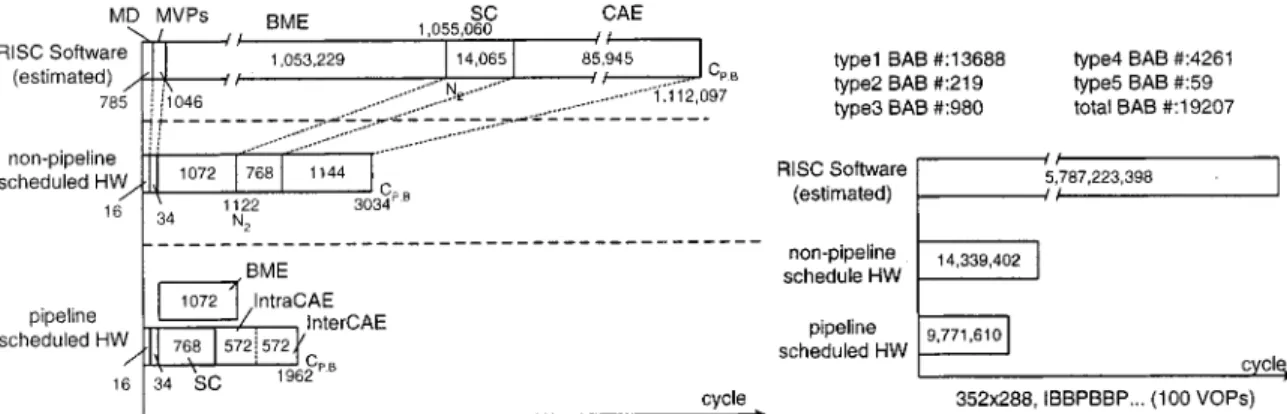
The optimized BME, CAE, and size conversion units are inte-grated with the mode decision, MVP units, and variable-length coding (VLC) units to achieve the complete function of the MPEG-4 shape coding. In order to achieve the maximum system performance, tasks of these hardware units are properly sched-uled. The worst-case scenario is the processing of the boundary BAB of P-VOP or B-VOP using inter-CAE coding mode. To complete one BAB processing in this worst-case scenario, the system architecture without task-pipelining configuration requires 3034 clock cycles: 16 clock cycles for mode decision, 34 clock cycles for identifying MVPs, 1072 clock cycles for BME, 768 cycles for size conversion, 1144 clock cycles for intra-CAE and inter-CAE, and 8 clock cycles for VLC. With BME computation and size conversion, intra-CAE can be processed in parallel; the processing flow can be scheduled as shown in Fig. 16. Based on this scheduling, the BAB of the worst-case scenario can be processed in 1962 clock cycles. For other types of BABs, their processing time is much shorter than the worst-case scenario (e.g., nonboundary BABs only require 16 clock cycles). Hence, the processing time of these types of BABs can be hidden within the inter-block pipeline for the worst-case scenario. In the real case simulation, the “bream” sequence of 100 CIF-format VOPs is tested. After the VOP formation processing, totally 19 207 BABs are encoded. Among them, 13 688 BABs belong to type 1 (as indicated in Fig. 18), 219 BABs belong to type 2, 980 BABs are type 3, 4261 BABs are type 4, and type 5 has 59 BABs. The processing time requires 9.54M cycles. This means the real-time shape coding (30 VOPs/s) of the “bream” sequence is easily achieved by the proposed pipelined architecture running at 3.2 MHz. The system performance comparison between software implementation and the proposed architecture is shown in Fig. 17.
The system architecture is implemented using Verilog HDL, and synthesized with 0.35 m four-layer metal CMOS standard library using Synopsys. The system architecture needs an area equivalent to about 30 k gates (on-chip memories excluded). For local data storage, three 16 16 and one 16 32 bits on-chip SRAMs are also required. The system architecture can easily achieve the real-time performance for CPL2 (7128 BABs of non-T/O/N types per second) at 23.5 MHz. The peak performance of this architecture when running at 40 MHz can support main profile level 3 (MPL3) specification.
VI. CONCLUSION
In this paper, a computation-efficient architecture of MPEG-4 shape coding is described. Due to the severe real-time con-straint, the software implementation of MPEG-4 shape coding at Core Profile Level 2 or higher specification cannot meet the necessary requirements. Although the bit-level parallelism can be applied to increase the performance of software implementa-tion, our analysis results reveal that the bit-data addressing will become the new computation bottleneck of BME computation. In other processings, such as CAE, size conversion cannot gain much from this bit-parallelism technique because of the bit-serial processing nature. Besides, the window-based processing nature leads to much redundancy of data transfer for software implementation. Accordingly, we propose sev-eral hardwired building blocks, such as DDBME, CAE, and DLM to speedup the performance of computation-extensive algorithms. In addition, they are integrated and scheduled in a proper data flow such that task pipelining can be smoothly proceeded to achieve the maximum system performance. The system architecture is implemented by synthesizable Verilog HDL, and synthesized with 0.35- m four-layer metal CMOS standard library. It can achieve the real-time performance for CPL2 specification at 23.5 MHz.
REFERENCES
[1] ISO/IEC JTC1/SC29/WG11, N2502a, “Generic Coding of Audio-Vi-sual Objects: ViAudio-Vi-sual 14 496-2,”, Atlantic City, Final Draft IS, Dec. 1998. [2] F. Pereira, “MPEG-4: Why, what, how and when,” J. Signal Processing:
Image Commun., vol. 15, pp. 271–279, 2000.
[3] N. Brady, “MPEG-4 Standardized methods for the compression of arbi-trarily shaped video objects,” IEEE Trans. Circuits Syst. Video Technol., vol. 9, pp. 1170–1189, Dec. 1999.
[4] N. Brady, F. Bossen, and N. Murphy, “Context-based arithmetic en-coding of 2D shape sequences,” in Proc. Int. Conf. Image Processing
(ICIP’97), vol. 1, 1997, pp. 29–32.
[5] J. Ostermann, “Efficient coding of binary shapes using MPEG-4,” in
Proc. Int. Conf. Image Processing (ICIP’98), vol. 1, 1998, pp. 295–298.
[6] J. Kneip, S. Bauer, J. Vollmer, B. Schmale, P. Kuhn, and M. Reibmann, “The MPEG-4 video coding standard—A VLSI point of view,” in Proc.
IEEE Workshop Signal Processing Systems Design and Implementation (SiPS’98), Oct. 1998.
[7] P. Kuhn and W. Stechele, “Complexity analysis of the emerging MPEG-4 standard as a basis for VLSI implementation,” Proc. SPIE
Visual Communications and Image Processing, 1998.
[8] D. Gong and Y. He, “Computation complexity analysis and VLSI archi-tectures of shape coding for MPEG-4,” in Proc. SPIE VCIP’2000, vol. 4067, June 2000, pp. 1459–1470.
[9] H.-C. Chang, Y.-C. Wang, M.-Y. Hsu, and L.-G. Chen, “Efficient al-gorithms and architectures for MPEG-4 object-based video coding,” in
Proc. IEEE Workshop on Signal Processing Systems Design and Imple-mentation (SiPS 2000), Oct. 2000.
[10] MPEG Requirements Group, “Overview of MPEG-4 profile and level definitions,” Dublin MPEG Mtg., Doc. ISO/MPEG N2325, July 1998. [11] M. Berekovic, K. Jacob, and P. Pirsch, “Architecture of a hardware
module for MPEG-4 shape decoding,” in Proc. Int. Symp. Circuits and
Systems (ISCAS’99), May 1999.
[12] J. Thinakaran, D.-J. Ho, and N. Ling, “An architecture for MPEG-4 bi-nary shape decoder,” in Proc. Int. Symp. Circuits and Systems (ISCAS
2000), May 2000.
[13] R.-B. Lee, “Subword parallelism with MAX2,” IEEE Micro, vol. 16, no. 4, pp. 51–59, Aug. 1996.
[14] J. L. Hennessy and D. A. Patterson, Computer Architecture—A
Quanti-tative Approach, 2nd ed. San Mateo, CA: Morgan Kaufmann, 1996. [15] H.-C. Chang, L.-G. Chen, M.-Y. Hsu, and Y.-C. Chang, “Performance
analysis and architecture evaluation of MPEG-4 video codec system,” in Proc. Int. Symp. Circuits and Systems (ISCAS 2000), May 2000.
[16] S. Bauer, J. Kenip, T. Mlasko, B. Schmale, J. Vollmer, A. Hutter, and M. Berekovic, “The MPEG-4 multimedia coding standard: Algorithms, architectures and applications,” J. VLSI Signal Processing, vol. 23, pp. 7–26, 1999.
[17] MPEG-4 VM software, European ACTS project MoMuSys, Apr. 1999. [18] W. Pratt, Digital Image Processing, 2nd ed. New York:
Wiley-Inter-science, 1991.
[19] P. Ruetz and R. Brodersen, “Architectures and design techniques for real-time image-processing IC’s,” IEEE J. Solid-State Circuits, vol. 22, no. 2, pp. 233–250, 1987.
[20] D. Coltuc and I. Pitas, “Fast computation of a class of running filters,”
IEEE Trans. Signal Processing, vol. 46, pp. 549–553, Mar. 1998.
[21] T. Komarek and P. Pirch, “Array architectures for block matching algo-rithms,” IEEE Trans. Circuits Syst., vol. 36, no. 10, pp. 1301–1308, Oct. 1989.
[22] C. H. Hsieh and T. P. Lin, “VLSI architecture for block-matching motion estimation algorithm,” IEEE Trans. Circuits Syst. Video Technol., vol. 2, pp. 169–175, June 1992.
[23] Y. K. Ko, H. G. Kim, J. W. Lee, Y. R. Kim, H. C. Oh, and S. J. Ko, “New motion estimation algorithm based on bit-plane matching and its VLSI implementation,” in Proc. IEEE Region 10 Conf., vol. 2, 1999, pp. 848–851.
[24] B. Natarajan, V. Bhaskaran, and K. Konstantinides, “Low-complexity block-based motion estimation via one-bit transforms,” IEEE Trans.
Circuits Syst. Video Technol., vol. 7, pp. 702–707, Aug. 1997.
[25] K.-M. Yang, M.-T. Sun, and L. Wu, “A family of VLSI design for the motion compensation block-matching algorithm,” IEEE Trans. Circuits
Syst. Video Technol., vol. 36, pp. 1317–1325, Oct. 1989.
[26] J. L. Mitchell and W. B. Pennebaker, “Optimal hardware and software arithmetic coding procedures for the Q-Coder,” IBM J. Res. Devel., vol. 32, no. 6, pp. 717–726, Nov. 1988.
[27] G. Feygin, P. Glenn, and P. Chow, “Architectural advances in the VLSI implementation of arithmetic coding for binary image compression,” in
Proc. Data Compression Conf. (DCC’94), 1994, pp. 254–263.
Hao-Chieh Chang was born in Taichung, Taiwan, R.O.C., in 1972. He received the B.S. degree in elec-tronics engineering from National Chiao Tung Uni-versity, Hsinchu, Taiwan, R.O.C., in 1994, and the M.S. and Ph.D. degrees in electrical engineering from National Taiwan University, Taipei, Taiwan, R.O.C., in 1996 and 2001, respectively.
He joined AVerMedia, Inc., Taipei, Taiwan, R.O.C., in 2001, where he is currently Deputy Manager for the R&D Division. His research inter-ests include video and image coding system, DSP architecture design, video signal processor design, and VLSI signal processing.
Yung-Chi Chang was born in Kaohsiung, Taiwan, R.O.C., in 1975. He received the B.S. and M.S. de-grees from the Department of Electrical Engineering, National Taiwan University, Taipei, Taiwan, R.O.C., in 1998 and 2000, respectively, where he is currently working toward the Ph.D. degree in electrical engi-neering in the Graduate Institute of Electronics Engi-neering.
His research interests include video-coding algo-rithms and VLSI architectures for image/video pro-cessing.
Wei-Ming Chao was born in Taipei, Taiwan, R.O.C., in 1977. He received the B.S. and M.S. degrees from the Department of Electronics Engineering, National Taiwan University (NTU), Taipei, Taiwan, R.O.C., in 2000 and 2002, respectively. He is currently working toward the Ph.D. degree in the Institute of Electronics Engineering, NTU.
His research interests include video-coding algo-rithms and VLSI architecture design.
Visiting Scholar in the Department of Electrical Engineering, University of Washington, Seattle. Since 1988, he has been with National Taiwan University, Taipei, Taiwan, R.O.C., where he is currently Professor of Department of Electrical Engineering and the Director of the Graduate Institute of Electronics Engineering. His research interests include DSP architecture design, video processor design, and video-coding systems.
Dr. Chen serves as Associate Editor of IEEE TRANSACTIONS ONCIRCUITS ANDSYSTEMS FORVIDEOTECHNOLOGY, IEEE TRANSACTIONS ONVERYLARGE SCALEINTEGRATION(VLSI) SYSTEMS, and IEEE TRANSACTIONS ONCIRCUITS ANDSYSTEMS—II: ANALOG ANDDIGITALSIGNALPROCESSING. He is also As-sociate Editor of the Journal of Circuits, Systems, and Signal Processing, and served as the Guest Editor of The Journal of VLSI Signal Processing-Systems for
Signal, Image, and Video Technology. He was the General Chairman of the 7th
VLSI Design/CAD Symposium and the IEEE Workshop on Signal Processing Systems: Design and Implementation (1999), and is the IEEE Circuits and Sys-tems Distinguished Lecturer (2001–2002). He received the Best Paper Award from the ROC Computer Society in 1990 and 1994. From 1991 to 1999, he re-ceived Long-Term (Acer) Paper Awards annually. In 1992, he rere-ceived the Best Paper Award of the 1992 Asia-Pacific Conference on Circuits and Systems in the VLSI design track. In 1993, he received the Annual Paper Award of Chinese Engineer Society. In 1996, he received the Outstanding Research Award from the National Science Council, and the Dragon Excellence Award from Acer. He is a Member of Phi Tau Phi.