國
立
交
通
大
學
光電工程學系碩士班
碩
士
論
文
提升三維多點互動系統使用者辨識能力之
多圖騰演算法開發
High-freedom 3D Interactive System
for Multi-user/Multi-touch by Multi-mark Algorithms
研 究 生:黃書怡
指導教授:戴亞翔 教授
黃乙白 教授
提升三維多點互動系統使用者辨識能力之
多圖騰演算法開發
High-freedom 3D Interactive System
for Multi-user/Multi-touch by Multi-mark Algorithms
研 究 生:黃書怡 Student:Shu-Yi Huang
指導教授:戴亞翔 Advisors:Ya-Hsiang Tai
黃乙白 Yi-Pai Huang
國 立 交 通 大 學 光 電 工 程 學 系 碩 士 班
碩 士 論 文
A ThesisSubmitted to Department of Electro-Optical Engineering College of Electrical and Computer Engineering
National Chiao Tung University in partial Fulfillment of the Requirements
for the Degree of Master
In Electro-Optical Engineering July 2012
Hsinchu, Taiwan, Republic of China
中華民國一百零一年七月
i
提升三維多點互動系統使用者辨識
能力之多圖騰演算法開發
碩士研究生:黃書怡
指導教授:戴亞翔教授
黃乙白教授
國立交通大學電機學院
光電工程學系碩士班
摘
要
近年來3D 顯示科技的蓬勃發展,使得影像跳脫傳統框架,栩栩如生地出現 在我們眼前。此外2D 觸控面板的爆炸性成長,使得多點觸控改變了使用者對於 人機介面的使用習慣與期待。鑒於立體影像已蔚為風潮,加上智慧型手機與平板 電腦的普及,未來將兩者結合之3D 智慧型手機與 3D 平板電腦已然成為趨勢。 然而要使3D 技術普及化,除了 3D 顯示設備外,擁有一個友善的人機互動 介面更是推動此項技術的關鍵,因此3D 互動系統將成為下世代的關鍵技術。為 了達成平面與三維空間的連續互動介面,我們選擇了內嵌光感測元件的架構,提 出適用於薄型可攜式電子顯示器之多點、以及多人三維立體近距離互動系統。 在以往的3D 多點/多人互動系統中,使用者間部分重疊的情況始終為一大困 擾,因此,經由所提出的演算法,包括時序性互動演算法、多圖騰式演算法等, 多位使用者可同時間的與系統進行三維互動並被成功的分辨。最後,所提出的演 算法被證實於內嵌光感測元件的4 吋面板上。多環形圖騰演算法提升了使用者的 辨識能力,解決了使用者間40%之重疊情形,同時獲得個別使用者之二維的位置 (x, y)以及深度資訊(z);另外,藉由多 T 形圖騰演算法,不僅是使用者的三維資 訊(x, y, and z),其傾斜與旋轉角度(θ, )等資訊也能夠被準確地截取出來。ii
High-freedom 3D Interactive System
for Multi-user/Multi-touch by Multi-mark Algorithms
Student: Shu-Yi Huang Advisors: Ya-Hsiang Tai, Yi-Pei Huang Institute of Electro-Optical Engineering
National Chiao Tung University
Abstract
Recently, the widespread of 2D multi-touch user interfaces has become a part of our lives. Meanwhile, the increasing popularity in 3D images dramatically changes the user experience. Therefore, by the fact of great mass fervor in smart phone and tablet computer, 3D smart phone and 3D tablet is undoubted the battle field of next generation technology.
However, a portable 3D device cannot be all-pervading if there is no friendly 3D multi-interactive user interfaces. Hence, in order to establish a continuous interaction space from 2D surface to 3D near field distance, the embedded optical sensor based structure is chosen in our approaches. However, for multi-user/multi-touch interactive systems, the users’ overlapping has been a serious issue in user recognition. Therefore, by the proposed methods, the sequential-lighting method and the multi-mark method, user overlapping issue might be solved. Three algorithms, the sequential-lighting algorithm, multi-ring mark algorithm, and the multi-T mark algorithm, and the accordant light marks are proposed to provide distinguishable 3D user interfaces. Finally, the feasibility of the proposed algorithms was demonstrated on a 4” panel with in-cell optical sensors. The ability of user identification can be improved to 40% overlapping by the multi-ring mark algorithm. Meanwhile, 5-axis information (x, y, z, θ, and ) including 3D coordinate and orientation can be obtained through the multi-T mark algorithm.
iii
誌
謝
誠摯的感謝指導老師戴亞翔教授、黃乙白教授,給予我進修碩士的機會,讓 我能藉此機會提升自我能力,不僅在於研究上、更對於未來的方向提供了寶貴的 意見。也感謝謝漢萍教授在碩士生涯的諸多指點。此外,由衷的感謝各位口試委 員提供的精闢見解,使本論文更加完備。 在此感謝王國振學長兩年來亦師亦友的教誨,其對於研究的嚴謹態度,實為 學弟妹的典範,不僅讓論文更加完善流暢,也讓我在研究方法以及報告技巧上學 習成長了許多。尤其要感謝馬明青學姐、董軒宇學長、以及馬志堯學長在我碩一 時不厭其煩的教導,帶領我渡過一次又一次的考驗。也感謝宣賀及正昌學弟在實 驗及研究上提供了十分寶貴的建議以及幫助,讓論文及實驗能順利完成。 在實驗室的日子裡,特別感謝綺文及博凱對我的照顧與陪伴,也感謝有林芳 正、陳致維、蔡韻竹、張育誠、蔡柏全、王奕智、許精益、丁志宏、任台翔、簡 又儀、謝博元等博班學長姐,提供專業的意見及教導,也感謝思頤、博詮、昌毅、 立偉、濟宇、禹辰、子寬等學長姐在我碩一這年的照顧。而碩二一起認真與玩樂 的同學們,白諭、秉彥、柏皓、上翰、哲軒、博鈞,也非常感謝你們在這兩年生 活上的幫助與分享。且要對實驗室的雅惠、純敏、蓮方、以及穎佳四位助理小姐 和學弟妹表達感謝,讓我們能沒有後顧之憂的做研究且讓實驗室充滿歡樂的氣 氛。 最後,我要感謝我們家人,謝謝你們這些年來的支持與鼓勵,並感謝我的朋 友們冠緯、祿盛、雅晴等,不論在何時都願意為我加油打氣,讓我能夠再次向前 出發,朝目標邁進。感謝我所認識的各位,讓我能順利完成碩士學位,這份喜悅 與榮耀我將與我認識的各位分享。iv
Contents
摘 要... i Abstract ... ii 誌 謝... iii Figure Captions ... vi Chapter 1 Introduction ... 1 1.1 Preface... 1 1.2 2D Multi-touch Technologies ... 21.3 Motivation and Objective ... 10
1.4 Organization of the Thesis ... 12
Chapter 2 Prior Arts of 3D interactive Systems... 13
2.1 2D Touching of 3D Stereoscopic Images ... 13
2.2 3D Virtual Touch Technologies ... 15
2.3 Machine-based ... 16
2.3.1 Haptic WorkstationTM ... 16
2.3.2 Wii ... 17
2.4 Camera-based ... 19
2.4.1 Microsoft 3D Gesture Interface ... 20
2.4.2 WorldViz PPT ... 21
2.5 In-cell Optical-based ... 23
2.5.1 ThinSight... 23
2.5.2 Sensible Backlight ... 24
2.5.3 Directional Image Sensor ... 26
2.5.4 Color-filter-based Sensing ... 27
2.5.5 Multi-mark Based ... 28
2.6 Summary of 3D Virtual Touch Systems... 30
Chapter 3 Structure and Algorithms ... 32
3.1 Overall Structure ... 32
3.2 Sequential-lighting Method ... 34
3.2.1 Synchronization ... 36
3.2.2 Noise Suppression ... 36
3.2.3 Full Search Method ... 37
3.2.4 Adaptive Window Method ... 37
v
3.3.1 Light-mark Design ... 41
3.3.2 Multi-ring Mark: Overlap Improvement ... 43
3.3.3 Multi-T Mark: 5-axis Information (x, y, z,
,
) ... 49Chapter 4 Experiments and Results ... 63
4.1 Experiment Setup ... 63
4.2 Sequential-lighting Method ... 64
4.3 Multi-ring Mark ... 67
4.3.1 Resolution in Z-axis ... 68
4.3.2 Overlapping with Normal Incident ... 70
4.3.3 Overlapping with Tilt Light-pen ... 73
4.4 Multi-T Mark ... 77
4.4.1 5-axis Information and User Identification ... 78
4.4.2 Resolution in Depth (z) ... 78
4.4.3 Resolution in Orientation (
, ) ... 79Chapter 5 Conclusion and Future Work ... 82
5.1 Conclusion ... 82
5.2 Future Work ... 84
vi
Figure Captions
Fig. 1. Trend of interfaces and 3D displays technologies. ... 2 Fig. 2. First 2D touch product with multi-touch user interface - JazzMutant’s Lemur
music.[4] ... 2 Fig. 3. Principle of capacitive sensing: when a voltage apply, (a) there exist a capacitance
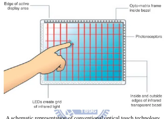
between X electrode and Y electrode. (b) once a finger touch the surface, there is a distortion in electrostatic field and the mutual capacitance is reduced. ... 3 Fig. 4. Working principle of position determination in projective capacitive sensing system. [6] ... 4 Fig. 5. Illustration of a resistive touchscreen. [6] ... 4 Fig. 6. A schematic representation of conventional optical touch technology. ... 5 Fig. 7. General set-up of a Frustrated Total Internal Reflection (FTIR) system which is
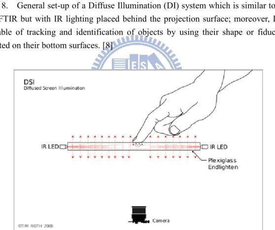
based on optical total internal reflection within an interactive surface; as a user touches the screen, the light escapes and is reflected at the finger’s point of contact, which is then detected by an IR camera at the back of the pane. [8] ... 6 Fig. 8. General set-up of a Diffuse Illumination (DI) system which is similar to that for
FTIR but with IR lighting placed behind the projection surface; moreover, DI is capable of tracking and identification of objects by using their shape or fiducially printed on their bottom surfaces. [8] ... 7 Fig. 9. General set-up of a Diffused Surface Illumination (DSI) system which utilizes small
number of (two or three) infrared illuminators and evenly distributed the light across the screen surface. [8] ... 7 Fig. 10. Schematic of a camera-based optical touch technology. [13] ... 8 Fig. 11. General cross-section of LCD in-cell optical touch panel. [14] ... 9 Fig. 12. 2D in-cell light-sensing can be achieved by (a) sensing the shadow of touching
objects caused by blocking the regional ambient light where (b) the objects’
positions reveal lower gray level [14]. ... 9 Fig. 13. (a) The prototype of capturing the reflection of IR backlight is employed in 2D
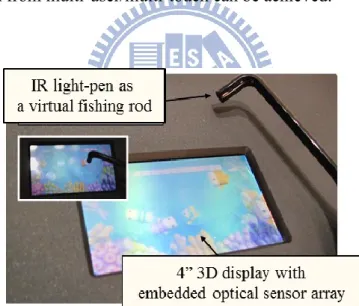
in-cell light-sensing where (b) the objects’ positions exhibit higher gray level. [15] 9 Fig. 14. Continuous interaction space from 2D touch surface to 3D virtual touch. [16]... 10 Fig. 15. A 3D virtual touch prototype demo – 3D Fishing Game. The video link:
http://youtu.be/ipJeMAdZVCI ... 11 Fig. 16. Depth perceptions are (a) behind and (b) in front of the display plane. [17] ... 14 Fig. 17. Main issue in 2D touch interface with stereoscopic data is that a user is either focus
on the finger or the 3D virtual objects which both degrades the visual perception. [18] ... 14
vii
Fig. 18. 5 axes (x, y, z, θ ,and ) information in position and orientation. ... 15 Fig. 19. Haptic Workstation and Head-Mounted Display (HMD) for rendering the virtual
cockpit. [19] ... 17 Fig. 20. Wii utilizes an infrared camera to sense a series of LEDs in the sensor bar, orienting
the controller in space.[22]... 18 Fig. 21. Acceleration Sensor: this chip provides all the motion sensing. A piece of silicon is
evenly placed between two capacitors in electric field. Once the user accelerates the controller in one direction, it causes the silicon to bend in the other and causes the electric field to change, which translates into motion.[22] ... 18 Fig. 22. Limited field of view in cameras causes the blind range, unworkable region, in
near-distance. ... 19 Fig. 23. Intrinsic characteristics in camera-based system render a tradeoff between
discontinuous working space and large system volume which forbids the integration to a display. ... 20 Fig. 24. Schematic of the Microsoft 3D Gesture Interface. ... 21 Fig. 25. Microsoft 3D Gesture Interface demonstrates that the “draw” command is activated when a “close loop” of shadow image is detected. ... 21 Fig. 26. 3D coordinate is acquired by tracking (a) active LED markers by at least two to (b) four tracking cameras. ... 22 Fig. 27. (a) Basic construction of ThinSight, and (b) applications in ThinSight display
including 2D finger multi-touch, data transformation between a mobile device and the display, and 3D gesture interaction through a device which can cast a beam of infrared light onto the display. [15] ... 23 Fig. 28. (a) Working principle and optical structure of the sensible backlight system, and (b) layout of backlight with RGB LEDs integrating with IR photo transmitters. [27] .. 25 Fig. 29. (a) Sensor image of touch, (b) sensor image of hover, (c) extracted touch points,
and (d) extracted hover points. [27] ... 25 Fig. 30. (a) Concept of a 3D input device using a directional image sensor, and (b)
structure of thin-film lateral diode and light shielding layers to create a directional field-of-view. [28] ... 26 Fig. 31. One dimensional representation of the response of two directional sub-pixels. [28]
... 27 Fig. 32. System structure of color filter based sensing. ... 28 Fig. 33. A detected image under red color filter. Undesired blue light penetrates a red color
filter and overlapping of red and blue spots occurs. ... 28 Fig. 34. Designed light marks of solid T shape, X shape, and circle. ... 29 Fig. 35. Complex overlapping conditions need to be processed case by case which results in heavy computation requirement. ... 29
viii
Fig. 36. Different categories of 3D interactive systems have different characteristics that
match for different applications. ... 31
Fig. 37. Hardware structure of the embedded optical sensors display. ... 32
Fig. 38. Concept of the proposed 3D virtual touch system with multi-user collaboration. .. 33
Fig. 39. A 3D interactive system model with sequential mark (a) light source one was turned on during frame = n×k+N=3k+1 where n equals to the number of users and N is the sequence of the user (b) light source two was turned on during frame = 3k+2 (c) light source three was turned on during frame = 3k+3, k=0,1,2… ... 34
Fig. 40. Flow chart of Sequential-lighting algorithm. ... 35
Fig. 41. Full search method: 2D coordinate (x and y) is defined by the maximum accumulation within the N by N search block. ... 37
Fig. 42. Adaptive window method is employed to detect the depth value (z), where a look-up table for window sizes is built according to the experiments. ... 38
Fig. 43. Hand gesture models. [33] ... 40
Fig. 44. Concept of (a) multi-touch for single user through light gloves [36] with Multi-ring mark and (b) multi-user interaction with 5-axis information by Multi-T mark approach. ... 41
Fig. 45. Principle of mark design including out-mark and in-mark, where out-mark determines the perceivable degrees of freedom, and in-mark is utilized for user identification. (a) Multi-ring mark design, (b) Multi-T mark design. ... 43
Fig. 46. Flow chart of Multi-ring mark algorithm. ... 43
Fig. 47. Structuring elements for morphological thinning. Ones and zeros stand for foreground and background pixels and the blanks can be either one or zero which we don’t care about. At each term, the image is first thinned by B1, then B2, as so on. The process is repeated until none of the thinning produces any further change. ... 45
Fig. 48. Light pens are positioned at 50mm and detected by the embedded optical sensors. Output images after image enhancement steps and thinning operation from the 1st term until convergence are shown. ... 45
Fig. 49. (a) Ring filter are constructed according to the size of out-mark at different heights, and (b) shows the structure element of ring filter at z=0. ... 46
Fig. 50. In candidate detection, the accumulation results at different ring filter (z) are divided by the corresponding normalizing factors. The local maximum with its value close to 1 will be defined as the candidates. ... 47
Fig. 51. In-mark window for in-mark extraction. ... 48
Fig. 52. Ranking process is able to define different users. ... 48
Fig. 53. Flow chart of Multi-T mark algorithm. ... 49
ix
Fig. 55. A practical example for Filling holes. (a) is the binary image by thresholding the captured image, and (b) shows the complement of the binary image in (a) for use as a mask image. (c) is the marker image, F, generated by Eq. (6). Finally (d) shows the image with all the holes filled. ... 52 Fig. 56. Connected-component labeling operator: (a) Row data of detected image converts
into binary image. After the first pass, the following labels are generated as (b). The label equivalence relationships are given in (c) and then (d) merging the equivalent labels with the label value that is the smallest for a given connected region. Final result (e) in color to clearly see two different regions that have been found ... 53 Fig. 57. Unique label on each connected regions are utilized to separate different marks to
different binary images. ... 54 Fig. 58. 2D coordinate of a T mark is acquired by the full search method, where the origin
of the maximum accumulation in search window (imax and jmax) is assigned to the 2D coordinate (x and y). ... 55 Fig. 59. (a) Orientation angles about z-axis is called the rotation angle (), and the tilt angle () is rotated about the axis parallel to the short branch. (b) A normal direction of a multi-T mark with the definition of short and long branches. ... 55 Fig. 60. (a) Rotation filters from 0 to 170 degree with 10 degree’s step where a normal T
with a long branch parallel to x-axis is defined to 0 degree. (b) Matrix of the rotation filter at 0 degree. ... 56 Fig. 61. Branch filters from 0 to 170 degree is able to define the orientation of short branch
in a multi-T mark. ... 57 Fig. 62. Multi-T marks with rotation filter 30 degree indicate the rotation angles of (a) 30
degrees or (b) 210 degrees. ... 58 Fig. 63. Image rotation and length of braches acquisition. ... 59 Fig. 64. Under different tilt angles, the branch ratio L/S changed accordingly. Hence L1/S1
≠ L2/S2 ≠ L3/S3. ... 60 Fig. 65. A comparison of various edge detectors with marks at different heights, which is a
function of z, and orientation, which is a function of . ... 61 Fig. 66. User identification is achieved by normalizing (N) each multi-T mark to the same
size and processing Prewitt edge filter (E) to extract in-mark feature. Finally the no. of user can be identified by ranking (R) the accumulation. ... 62 Fig. 67. Prototype of the 3D multi-interactive system with 4-inch sensible LCD notarizes
the proposed algorithms. ... 64 Fig. 68. Model of three users cross over: User 1 and 2 meet at position B and User 1 and 3
meet at position C where the overlapping might occur. ... 64 Fig. 69. (a) Without applying sequential-lighting method, three light marks are captured
x
users cannot be identified. ... 65
Fig. 70. Images captured by the optical sensors with 30 Hz sampling rate under sequentially illuminating method. Each light-pen was set to be 10 Hz and synchronized with the optical sensors. ... 65
Fig. 71. Multi-ring mark includes two parts: one is out-mark for tracking 3D coordinate (x, y, and z), the other is in-mark for user identification. ... 67
Fig. 72. Experiment results of 3-axis detection and user recognition in Multi-ring mark system. ... 68
Fig. 73. Look-up table (LUT) for depth determination in multi-ring mark system ... 69
Fig. 74. 5 positions for height measurement. ... 69
Fig. 75. Experiment results in depth detection with 5 mm step. ... 69
Fig. 76. Percentage of overlapping is defined as l / D, where l represents the length of overlap section and 𝑫𝒎𝒊𝒏 is the minimum diameter of the projected light marks. ... 70
Fig. 77. In normal incident condition, the percentage of overlapping increase as the height of the light pens increase. ... 71
Fig. 78. Overlap of user1 and user2 in vertical movement. ... 72
Fig. 79. Overlapping of user1 and user3 in vertical movement. ... 72
Fig. 80. Overlapping of user2 and user3 in vertical movement. ... 73
Fig. 81. Serious overlapping conditions can be attained by tilting the light pens. ... 73
Fig. 82. Result of two marks overlapping experiment from 0 to 100% ... 75
Fig. 83. Result of three marks’ overlapping experiment. ... 76
Fig. 84. Multi-T Marks are utilized to determine 5-axis information by out-mark T and meanwhile achieve user identification by in-mark, the inner blocking strips. ... 77
Fig. 85. Schematic of orientation coordinates where rotation angle () and tilt angle () are the angles rotate about the short bar of T and z-axis respectively. ... 77
Fig. 86. Experiment results of 5-axis detection and 3-user recognition. ... 78
Fig. 87. Look-up table for depth value detection by using the length of the short branch. .. 78
Fig. 88. Result of depth measurements... 79
Fig. 89. Result of tilt angle measurements. ... 80
Fig. 90. Result of rotation angle measurements. ... 80
Fig. 91. Summary of the proposed systems. ... 82
Fig. 92. Structure for the bare-hand 3D multi-touch system. ... 85
1
Chapter 1
Introduction
Introduction
1.1 Preface
Recent years, the battle field of technology competition has moved from the hardware into the software. The software competition, to be more precise, refers to pursuit of a friendly user interface and a better user experience. As shown in Fig. 1, in the early 1870s, C. Sholes invented the QWERTY keyboard [1] as an input device for a computer. Until 1964, the first prototype computer mouse [2] was made to use with a graphical user interface. In the next year, the first two-dimensional (2D) touch screen was developed. However, the touch technology does not dramatically change the user habits until the bump up of the smart phone. In the beginning of 21st century, the wide adoption of smart phones and tablets have accelerated a user interface transformation and paved the way to multi-touch technologies. Multi-touch technologies started to play an important role in our lives. It became so unexpendable in today’s world since Apple established multi-touch as a “must-have” technology. The result is that people of all ages expect every display to be touchable with multiple fingers.
2
Fig. 1. Trend of interfaces and 3D displays technologies.
1.2 2D Multi-touch Technologies
Multi-touch technology is defined as the ability to recognize two or more contact points at the same time. [3] In 2004, the first commercial product JazzMutant’s Lemur music [4], as shown in Fig. 2, brings multi-touch technology into our lives.
Fig. 2. First 2D touch product with multi-touch user interface - JazzMutant’s Lemur music.[4]
At present, the mainstream of 2D multi-touch technologies are projected capacitive, analog resistive, and camera-based optical. These technologies increase the flexibility between human and machine by allowing a user to simultaneously control rotation, scaling, and translations (RST) form multi-touch gestures [5]. More
3
intuitive interactions and user interfaces have been achieved due to multi-touch technologies. In the following paragraphs, we’ll briefly describe these technologies.
Projected Capacitive: In the projected capacitive sensing system, there is a
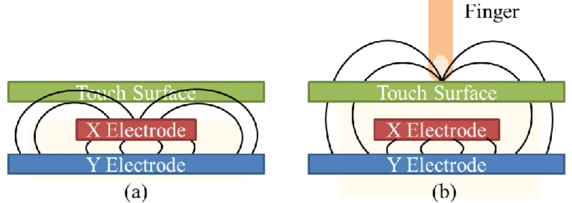
capacitor at every intersection of each row and each column. A voltage is applied to an X-Y grid, which is an electrode consisting of a matric of drive lines and sense lines, to form a uniform electrostatic field. As a finger or conductive stylus touches or close enough to the surface of the screen, it renders a distortion in the local electrostatic field, as shown in Fig. 3. The capacitance change at every individual point on the grid can be measured to accurately determine the touch location, as illustrated in Fig. 4. A single drive line is excited with an ac signal. The capacitance at each intersection between the drive line and each sense line is measured simultaneously. Next, multiplexer outputs the measured values and next being converted into a digital data stream by an A/D converter. Digital signal processing (DSP) is thus employed to interpret the data stream to 2D (x and y) coordinate of the touch location on screen surface.
Fig. 3. Principle of capacitive sensing: when a voltage apply, (a) there exist a capacitance between X electrode and Y electrode. (b) once a finger touch the surface, there is a distortion in electrostatic field and the mutual capacitance is reduced.
4
Fig. 4. Working principle of position determination in projective capacitive sensing system. [6]
Analogue Resistive: An analogue resistive touchscreen panel is composed of
several layers, as shown in Fig. 5. The sensing layer is constructed of two sheets of material separated slightly by spacers: a sheet of glass providing a stable bottom layer and a sheet of Polyethylene (PET) as a flexible toy layer. The two sheets are coated with a resistive material, usually a metal compound Indium Tin Oxide (ITO) and separated by an air gap or microdots. When an object, such as a finger, presses down on a point on the outer surface, the two metallic layers connected at the point. This causes a change in the electrical current, which is registered as a touch event and sent to the controller for processing. Hence the position of the touch on the surface can be measured.
5
Optical: In conventional optical touch technology [7], an array of infrared (IR)
LEDs were allocated on two adjacent bezel edges of a display with photo sensors placed on the two opposite bezel edges to determine a touch event. The photo sensor outputs can be used to locate a touch-point coordinate, as shown in Fig. 6.
Fig. 6. A schematic representation of conventional optical touch technology.
Although the traditional type of optical touch has been hampered by two factors, the relatively high cost compared to competing touch technologies and the issue of performance in bright ambient light, certain features of optical touch remain desirable and represent attributes of the ideal touch screen. For examples, the option to eliminate the glass or plastic overlay that maintain the display quality, the digital nature of the sensor output, no direct impact of a touch object, and multi-touch implementation are the promising features in optical-touch technology.
There are several new types of optical-touch systems that is able to detect multiple touches, for instance, vision-based, camera-based, and LCD in-cell optical touch.
6
Vision-based optical touch systems [8] employ one or more IR imaging cameras
to capture the image of the entire screen, which usually means that the camera must be located a significant distance away from the screen. Therefore, most vision-based touch systems, like frustrated total internal reflection (FTIR) [9][10], diffuse illumination (DI) [11], and diffused surface illumination (DSI) [12] systems as illustrated in Fig. 7 to Fig. 9, are implemented with the detecting cameras located behind a projection-screen surface and process the captured images to determine the 2D coordinates of touching objects.
Fig. 7. General set-up of a Frustrated Total Internal Reflection (FTIR) system which is based on optical total internal reflection within an interactive surface; as a user touches the screen, the light escapes and is reflected at the finger’s point of contact, which is then detected by an IR camera at the back of the pane. [8]
7
Fig. 8. General set-up of a Diffuse Illumination (DI) system which is similar to that for FTIR but with IR lighting placed behind the projection surface; moreover, DI is capable of tracking and identification of objects by using their shape or fiducially printed on their bottom surfaces. [8]
Fig. 9. General set-up of a Diffused Surface Illumination (DSI) system which utilizes small number of (two or three) infrared illuminators and evenly distributed the light across the screen surface. [8]
For a vision-based optical touch system, 2D multi-touch can be successfully achieved. However, the large system volume is essential. Therefore, a camera-based optical touch technology has been developed to reduce the size of the system.
8
Camera-based touch technology utilizes at least two line-scanning cameras, as
illustrated in Fig. 10, located at adjacent corners of a display. The light source is usually one or two IR LEDs that are integrated into each camera assembly. The light is emitted in a plane across the surface of the screen and is reflected back to the cameras by retro-reflecting strips located along three edges of the screen.
Fig. 10. Schematic of a camera-based optical touch technology. [13]
However, a thick bezel must be fabricated due to the illumination of IR light upon display surface. Hence, LCD in-cell optical touch is proposed to maintain the virtue of thin form factor in a display.
LCD in-cell optical touch, also called “in-cell light-sensing,” establish by
integrating light sensing element (photodiode or photo transistor) into some or all of an LCD’s pixels, as illustrated in Fig. 11, which allows the display to act as a large array photosensor. The photo sensors receive light by either sensing the shadow of touching objects causes by blocking the ambient light [14] , as shown in Fig. 12 or the reflected light from infrared emitters embedded in the LCD’s backlight [15], as shown in Fig. 13; a multi-touch controller samples each photosensor and calculates the X-Y coordinates of touching objects.
9
Fig. 11. General cross-section of LCD in-cell optical touch panel. [14]
(a) (b)
Fig. 12. 2D in-cell light-sensing can be achieved by (a) sensing the shadow of touching objects caused by blocking the regional ambient light where (b) the objects’ positions reveal lower gray level [14].
(a) (b)
Fig. 13. (a) The prototype of capturing the reflection of IR backlight is employed in 2D in-cell light-sensing where (b) the objects’ positions exhibit higher gray level. [15]
10
1.3 Motivation and Objective
Although multi-touch has not been widely deployed in the past, there has recently been renewed interest in it, driven by new devices such as the iPhone that make multi-touch an integral part of the user interface. Meanwhile, the rapid grow up of 3D display technology has a dramatic impact on user experiences. The increasing interest in auto-stereoscopic image has given rise to an attention to 3D near distance interaction. However, the gains in the performance of 3D graphics hardware and rendering system have not been matched by a corresponding user interface to interact with the virtual 3D images we create. Therefore, in order to meet the trend in the future 3D mobile devices such as 3D cell phone and 3D tablet, there is an urgent need of 3D interactive interfaces that can provide multi-user/multi-touch, continuous, high-freedom, friendly interaction and at the same time integrable with portable devices.
As more and more researchers devoted in 3D interaction technology development, different approaches have been proposed which will be examined in the following chapter. In order to establish a continuous working space, as shown in Fig. 14, from a surface to near region, in-cell optical-touch seems to be one of the most promising technologies to extend from 2D to 3D multi-interaction.
Fig. 14. Continuous interaction space from 2D touch surface to 3D virtual touch. [16]
11
A 3D virtual touch system for a single user has been successfully demonstrate on a 3D auto-stereoscopic display with in-cell optical-sensor, as shown in Fig. 15, in 2010 FPD show. However for the existing 3D near distance interactive systems, there is still no satisfactory solution for multi-user/multi-touch user interfaces, which experience limitation in number of user, complex signal-processing demands (which adds cost and power consumption), and incomplete user identification for users overlapping. Therefore, our objective is to improve the performance and overcome the present issues in 3D near distance interfaces for multi-user/multi-touch interaction. By increasing the number of users, enhancing the user identification ability, and increasing the acquisition coordinates of a user, a high-freedom and friendly 3D interactive system from multi-user/multi-touch can be achieved.
Fig. 15. A 3D virtual touch prototype demo – 3D Fishing Game. The video link:
12
1.4 Organization of the Thesis
In the following paragraphs, we’ll briefly describe different 3D virtual touch technologies in chapter 2 and the reason for choosing in-cell optical-based display as our basic structure. The proposed system and the according algorithms are discussed in chapter 3. Next several experiments had been done to demonstrate the feasibility of the system in chapter 4. Finally the conclusion and future work are given in the last chapter.
13
Chapter 2
Prior Arts of 3D interactive Systems
Prior Arts of 3D interactive Systems
2.1 2D Touching of 3D Stereoscopic Images
In recent years, two technologies have dominated technical exhibitions and the entertainment market: multi-touch interface and 3D stereoscopic displays. A stereoscopic image means we can perceive a 3D virtual object jump out of the display plane. It is achieved by sending each eye a slightly different perspective of the same scene which results in two image projections on the display. By visual processing, our brains can automatically combine the two images and the 3D virtual object with depth perception will appear at the focus point, as illustrated in Fig. 16. Additionally, by considering the comfort of a viewer, up to plus and minus 5 cm of depth value is constructed for an auto-stereoscopic image which means a 3D image can be observe without wearing 3D glasses.
However, an issue occurs when a user wants to interact with a 3D virtual object of stereoscopic image. While in 2D touch interface, the user is either focus on the finger, which makes the selection ambiguous and breaking into two images, or on the virtual object, which disturbs the visual perception of the finger, as shown in Fig. 17.
14
Fig. 16. Depth perceptions are (a) behind and (b) in front of the display plane. [17]
Fig. 17. Main issue in 2D touch interface with stereoscopic data is that a user is either focus on the finger or the 3D virtual objects which both degrades the visual perception. [18]
Therefore, the 3D virtual touch technology is essential to provide a friendly and intuitive user interface to a 3D display or other interactive applications. More details will be discussed as follow.
15
2.2 3D Virtual Touch Technologies
To fulfill the demand in 3D (x, y and z) interaction applications such as in 3D stereoscopic display, much research has been devoted to 3D virtual touch technologies. Beside 2D coordinates (x and y) on the surface plane, extra depth information (z) is compulsory to specify a point in a 3D environment. However, rather than using points, many tasks in 3D systems require a user to manipulate entire objects which also have an orientation specified by orientation (θ and ) information. Thus there are 5 axes, as illustrate in Fig. 18, need to be defined in a 3D interactive system.
Fig. 18. 5 axes (x, y, z, θ ,and ) information in position and orientation.
3D virtual touch technologies, which are most widely used today, can be classified into three major groups in accordance with the employed techniques. Following paragraphs give further details of 3D virtual touch technologies in machine-based, camera-based, and in-cell optical-based.
16
2.3 Machine-based
The machine-based system is a robust 3D information detection approach where a user has to wear additional equipment to track his or her movement. Potentiometers or optical encoders are usually used to measure the rotation of a joint between rigid linkages of the equipment. Given the angle of each joint and length of the rods, the position of the tracked object can be calculated geometrically. Therefore, the position and orientation information can be obtained.
In machine-based 3D virtual touch systems, higher resolution information can be achieved by a more delicate and complex mechanical design. By wearing the solid equipment onto the body, it is possible to render force-feedback to the user; however, it is on the contrary uncomfortable for long time wearing and impractical to carry around with portable devices. Therefore, the machine-based system is often indoor fixed and collaborating with applications such as desktop set-up or virtual reality chambers.
2.3.1 Haptic Workstation
TMThe Immersion Haptic WorkstationTM [19] is an example of implementing machine-based virtual touch system to interact with virtual environments, as shown in Fig. 19. It is composed of data gloves [20], 5-axis hand tracking and force-feedback on the wrists. A pilot can see virtual images by the Head-Mounted Display (HMD) to simulate the flying conditions inside a blimp capsule through data gloves, and can also feel how fast he is going by evaluating the force applied on his hands. In [21], Ott et al have shown that the teleoperation of a vehicle using haptic devices is more efficient when having a gesture interface. However, one disadvantage of the Haptic
17
WorkstationTM is that it is uncomfortable during long sessions, because the user arms must be kept outstretched while supporting the weight of the exoskeleton.
Fig. 19. Haptic Workstation and Head-Mounted Display (HMD) for rendering the virtual cockpit. [19]
2.3.2 Wii
The Nintendo Wii video game console redefines the way how video games are played. The controller, Wii-mote [22], is able to translate a player’s motion, such as swinging and punching, into game playing on the screen. The working principle of Wii is hybrid both the camera-based and machine-based techniques to obtain the translation and rotation information. As shown in Fig. 20, there is an infrared camera in a Wii-mote. Thus, only the relative position can be calculated by sensing a series of corresponding LEDs in the sensor bar but without obtaining the absolute depth value. To increase the freedom in gestures, a machine-based technique, a three coordinates accelerometer [23], as shown in Fig. 21, is employed to detect the acceleration along three axes (x, y, and z). Hence different gestures, like wave, twist, push and pull can be achieved. To take the field of view in IR camera into consideration, a user must stand at 1 to 2 meter form the sensor bar in order to capture the full motion of the user. Hence, it is neither applicable for on screen surface nor in near distance region interaction.
18
Fig. 20. Wii utilizes an infrared camera to sense a series of LEDs in the sensor bar, orienting the controller in space.[22]
Fig. 21. Acceleration Sensor: this chip provides all the motion sensing. A piece of silicon is evenly placed between two capacitors in electric field. Once the user accelerates the controller in one direction, it causes the silicon to bend in the other and causes the electric field to change, which translates into motion.[22]
19
2.4 Camera-based
Commercial products collaborating with camera-based 3D virtual touch technology have dominated recent entertainment market. In many applications, the camera-based 3D interactive system is becoming pervasive and much more physical and tangible. Various designs of camera set-up and different sensing methods have been proposed, such as shadow sensing H.J. Luinge, P.H. Veltink, "Inclination measurement of human movement using a 3-D accelerometer with autocalibration," Neural Systems and
Rehabilitation Engineering, IEEE Transactions, vol.12, no.1, pp.112-121, 2004.
[24] and active light sensing [25] techniques. Complex image processing is applied on the high resolution images captured by the cameras to calculate the transition and/or rotation information.
However, limited field of view of cameras, as shown in Fig. 22, prevents the camera-based technology from integrating into portable devices. Objects proximity to the display cannot be detected which makes it difficult to perform a continuous interaction space from 2D to 3D. Hence, the camera-based 3D interaction system is more suitable for far-distance applications, such as to TVs or tabletop displays. Otherwise, the system volume must be increased for capturing the full vision of the interaction region, as shown in Fig. 23. Meanwhile, since the camera-based system requires high resolution data to calculate 3D information, a larger size of CCD is needed which impedes the system being integrated into portable devices.
20
in near-distance.
Fig. 23. Intrinsic characteristics in camera-based system render a tradeoff between discontinuous working space and large system volume which forbids the integration to a display.
2.4.1 Microsoft 3D Gesture Interface
In 2011, Microsoft set out a gesture control interface that a user can interact beyond the touchscreen H.J. Luinge, P.H. Veltink, "Inclination measurement of human movement using a 3-D accelerometer with autocalibration," Neural Systems and
Rehabilitation Engineering, IEEE Transactions, vol.12, no.1, pp.112-121, 2004.
[24]. The system composes of a retro-reflective screen, an image projector, and an infrared camera, as depicted in Fig. 24. The incident light from the projector is reflected back by the retro-reflective screen, which consists of many retro-reflectors, along a vector parallel to but opposite in direction from the source. Therefore the reflected light is captured by the camera with minimum scattering. Once a user put hands above the display, the shadow of hands can be detected. Without touching on the display surface, the 3D virtual touch can be achieved by gesture recognition, as shown in Fig. 25.
21
Fig. 24. Schematic of the Microsoft 3D Gesture Interface.
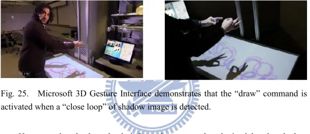
Fig. 25. Microsoft 3D Gesture Interface demonstrates that the “draw” command is activated when a “close loop” of shadow image is detected.
However, the absolute depth information cannot be obtained by the shadow method where only a camera is employed. Moreover, the projector and the IR camera must be located a significant distance away from the screen in order to display and capture the entire working space. The cost of retro-reflective screen is relatively high. The 3D gesture interface proposed by Microsoft is not suitable for thin-form display integration.
2.4.2 WorldViz PPT
WorldViz PPT (Precision Position Tracking) system [25] is available to obtain 5 axes data from the active LEDs which are put on the object, as shown in Fig. 26. Two or more cameras which are deployed in the workspace are able to track up to 32
22
visible infrared LED markers simultaneously. As the object with markers makes its way through the workspace, the cameras acquire data. Through image processing, the captured data are converted into accurate 3D coordinates, and the rotation information can be obtained through the relative movements between the markers.
Fig. 26. 3D coordinate is acquired by tracking (a) active LED markers by at least two to (b) four tracking cameras.
WorldViz PPT is a reliable solution for wide area 3D coordinate tracking which can be further applied on 3D far-distance interaction applications. However, it is not an ideal sensing system for portable devices because of the blind range limitation which enlarges the system volume, and the acquisition of high resolution cameras which distinctly increases the cost.
23
2.5 In-cell Optical-based
The in-cell optical-based 3D virtual touch system is the extension of the 2D in-cell multi-touch system. The continuous space from 2D surface to 3D virtual touch can be achieved without hybrid other mechanisms since they share the similar structure which was firstly proposed by W.D. Boer et al at 2003 [26]. Meanwhile, objects can be sensed under similar working principles; a hovering object can be detected either by the reflected light which is emitted by infrared LEDs in the LCD’s backlight, or by the object direct illumination on the display. Several techniques were proposed to determine the 3D coordinate (x, y, and z) and/or orientation (θ, and ) information.
2.5.1 ThinSight
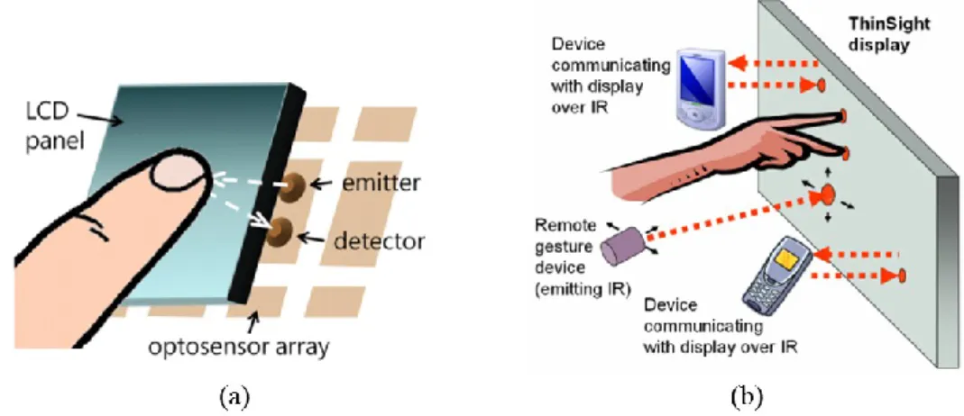
The idea of extending 2D multi-touch to 3D interaction in an in-cell optical-based system was first proposed by S. Hodges et al in 2007 [15]. A hardware structure with infrared sensors and emitters integrated into a thin form-factor display was suggested to detect multiple fingers placed on or infrared-emissive objects near the display surface, as shown in Fig. 27 (a).
24
display including 2D finger multi-touch, data transformation between a mobile device and the display, and 3D gesture interaction through a device which can cast a beam of infrared light onto the display. [15]
The layer of diffusing film between the LCD itself and the brightness enhancing film is removed because it cause too much attenuation of the infrared signal, especially for passive objects that reflect the light emitted from the display. However, the removal of diffuser has a detrimental effect on brightness and viewing angle of the LCD panel. Besides, it is not able to provide depth information. Still, based on the structure, a number of promising applications, such as data transformation, and 3D gesture interaction through an IR emitting device are proposed, as shown in Fig. 27 (b).
2.5.2 Sensible Backlight
A multi-touch LCD display architecture with hover sensing capability was proposed by K. Yi et al in 2010 [27]. Instead of changing an LCD manufacturing process to insert photo sensors in cell, the system proposes a sensible backlight where a backlight unit is integrated with an IR sensor array, as shown in Fig. 28. IR light sources for touch and hover detection are positioned on the bezels of the display. The 2D multi-touch is achieved based on frustrated total internal reflection (FTIR). For recognizing simple hovering objects, side IR illuminators emit light with tilt angles. Hence the approximate hovering positions can be obtained by sensing the reflected light by the IR sensors sensible backlight.
25
Fig. 28. (a) Working principle and optical structure of the sensible backlight system, and (b) layout of backlight with RGB LEDs integrating with IR photo transmitters. [27]
Fig. 29. (a) Sensor image of touch, (b) sensor image of hover, (c) extracted touch points, and (d) extracted hover points. [27]
The 2D multi-touch and hover positions can be obtained by utilizing the sensible backlight system. However, the depth information cannot be found, as shown in Fig. 29 (d). The approximate hover position, which is determined by the center of mess of each captured image, outputs a 2D coordinate on the surface. Moreover, a thicker border is needed for illuminated infrared light on the hover objects, and the panel size is limited by the intensity of side illuminated light. Therefore, the system is more
26
applicable on middle size displays with near-distance interaction.
2.5.3 Directional Image Sensor
A LCD system with integrated 3D input device was proposed by C. Brown et al in 2010, [28] and the concept is illustrated in Fig. 30 (a). The 3D input function is successfully achieved by employing directional image sensors integrated onto the TFT substrate. The directionality of the image sensor is created by an upper light shield formed in a second additional metallization layer, as depicted in Fig. 30 (b), to allow only incident light within a specific angle being detected. A set of four orthogonal direction sensors is able to generate four unique directional sub-images from the detected light. Sub-images are then processed to extract planar coordinates (x,y) corresponding to the location of the peak output signal, as shown in Fig. 31. Finally, by examining the relative displacement (d) of the object’s 2D coordinate in each directional sub-image, the depth value (z) can be calculated by Eq. (1).
d = 1
2 𝑧 ∙ cos 𝜃
Eq. (1)
Fig. 30. (a) Concept of a 3D input device using a directional image sensor, and (b) structure of thin-film lateral diode and light shielding layers to create a directional field-of-view. [28]
27
Fig. 31. One dimensional representation of the response of two directional sub-pixels. [28]
However, due to the construction of the panel, limited field-of-view of the directional sensor, and the insufficient sensitivity of the image sensor, detected z-axis exhibits a limited linear response from 0 to 20 mm. It is not enough for near field 3D interaction where 50 mm depth can be perceive in an auto-stereoscopic display. Meanwhile, the shielding layer above the photo sensor significantly reduced aperture ratio which makes the system hard to be implemented on mobile devices because of the considerable power consumption.
2.5.4 Color-filter-based Sensing
A 3D multi-interactive system achieved by color filter based sensing was proposed by H.Y. Tung, et al [29] under in-cell optical based structure where photo sensors are embedded on a TFT substrate in a LCD. As illustrated in Fig. 32, multi-wavelength of light sources, red, green, and blue are utilized as interaction illuminators. By using a color filter as a band-pass filter, different users can be identified by extracting the sensor outputs under accordant color filters. After separating light sources, center and radius of each circle are calculated and used to determine the 2D coordinate (x and y) and height (z) respectively. Therefore, 3D multi-touch interaction with user recognition can be achieved.
28
Fig. 32. System structure of color filter based sensing.
However, due to the usage of visible light sources, the display quality is degraded. The limited number of three users can be achieved due to the limited kinds of color filter in a display. Moreover, the imperfection of color filter would result in light leakage where light spots are too close and overlapping happens, as shown in Fig. 33. Nevertheless, a complex image processing, Hough transform, needs to be applied for circle detection which results in heavy computation.
Fig. 33. A detected image under red color filter. Undesired blue light penetrates a red color filter and overlapping of red and blue spots occurs.
2.5.5 Multi-mark Based
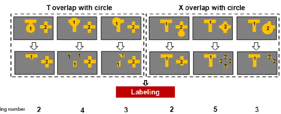
A 3D multi-mark interactive system was proposed by C.C. Chao, et al [30] to establish an interface between multiple users and 3D images. Based on the in-cell optical-sensor structure, illuminators such as IR light pens covering with designed marks, as shown in Fig. 34, is utilized to provide significant features. The display quality can be maintained by utilizing IR LEDs. By the proposed algorithm, different
29
users and their 3D coordinate (x, y, and z) can be identified. Meanwhile, the overlay of a circle with one of other marks, T or X, can be distinguished for up to 40% overlapping. Finally, the proposed algorithm was successfully demonstrated on a 4” panel.
Fig. 34. Designed light marks of solid T shape, X shape, and circle.
However, the limited of 3 users can be achieved due to the specific designed mark. Meanwhile, the complex overlapping cases, as illustrated in Fig. 35, dramatically increase the loading on a circuit, which also increases the cost and power consumption. Moreover, due to the similar characteristic of T shape and X shape, the overlapping of T and X cannot be identified in the system where only two users overlapping with one of them must be a circle can be deal with.
Fig. 35. Complex overlapping conditions need to be processed case by case which results in heavy computation requirement.
30
2.6 Summary of 3D Virtual Touch Systems
There is no perfect touch technique since the diversified products demands, as shown in Fig. 36. Machine-based systems are the most precise and reliable 3D interactive systems that can further render the force-feedback. However, the high cost due to the delicate apparatus and the inconvenience of device-wearing make the machine-based system mostly apply to military or medical training system or other elaborate applications. On the other hand, camera-based systems are more cost effective and produce rich data which provide enough reliability. Most of them by nature rely on projection and well-distance cameras capturing. Therefore, long-distanced and wide-area position tracking applications, such as tabletop display, TV, and interactive billboard, are more collaborated with camera-based systems.
The bump up in smart phone and tablet computer bring the mobile devices into the major consumer electronic products. Meanwhile, since the increasing interests in 3D applications and the gains in the auto-stereoscopic image performance, portable devices with 3D technology might soon be ubiquitous. Nonetheless, the technologies on the market neither match the requirements in mobile devices nor establish a robust continuous interaction space from 2D to 3D. Therefore, a potential solution refers to the in-cell optical-based technology which is able to maintain the thin form factor, to detect multiple touches, to preserve optical performance, and easy to carry with.
However, there are several issues in present multi-user/multi-touch user interfaces, such as limitation in number of users, complex signal-processing demands, and insufficient user identification ability. Therefore, in the following chapters, 3D virtual touch systems with multi-touch and user calibration (which means identifiable users) will be presented. Meanwhile, the proposed algorithm shall further increase the number of users, reinforce the user identification ability, and/or increase the detected
31
axes of users. Hence, a high-freedom 3D interface for multi-user/multi-touch could be achieved.
Fig. 36. Different categories of 3D interactive systems have different characteristics that match for different applications.
32
Chapter 3
Structure and Algorithms
Structure and Algorithms
3.1 Overall Structure
Fig. 37. Hardware structure of the embedded optical sensors display.
In order to maintain thin form factor as well to interact in near region to a display, the in-cell optical-based structure is chosen. The optical sensors are integrated onto the same layer with TFT substrate to form a sensor array all over the display, as shown in Fig. 37. For an in-cell optical-based display, the bare-finger interaction currently has some limitations, such as insufficient sensor resolution, serious ambient light effect, and inadequate depth sensing range. Therefore, an infrared LED light pen is utilized as the input device. The concept of the proposed 3D virtual touch system is illustrated in Fig. 38.
33
Fig. 38. Concept of the proposed 3D virtual touch system with multi-user collaboration.
In 3D virtual multi-touch technologies, three major issues need to be conquered. The first one is the limitation in number of users; there should be a more plastic method for the extension amount of users. The second issue is user recognition; instead of sacrificing the display quality or increasing the complexity of signal-processing to identify different users, a more simple but solid solution should be proposed. The last but not least one is the unsatisfactory user identification ability especially during overlapping cases. Therefore in the following paragraphs, two methods, Sequential-lighting method and Light-mark method which includes Multi-ring mark and Multi-T mark algorithms, will be presented to achieve a high-freedom 3D interaction system with 3D coordinate (x, y, and z) and/or orientation (θ and ) information detection and multi-user calibration. Meanwhile, the performance of the system shall be superior to the previous methods by solving the issues as mention.
34
3.2 Sequential-lighting Method
In Sequential-lighting method, the light pens are synchronized to the panel with embedded optical sensors. Each light pen emits light which is match to a frame of the sensor respectively. By sequentially turning on and off the light sources at 1/n frame rate of the optical sensor, where n equals to the number of the users, there will be only one light spot captured at a sensor frame. For instance, we match three light pens, which meant three users at a time, to the proposed panel, as illustrated in Fig. 39. For the first sensor frame, only the light pen one is turned on, while two others are turned off. For the second sensor frame, the light pen two is turned on while others are off, and so forth. Under sequentially turned the light pens on and off, there is always only one light spot received by optical sensors, which therefore overcome the overlapping issue.
Fig. 39. A 3D interactive system model with sequential mark (a) light source one was turned on during frame = n×k+N=3k+1 where n equals to the number of users and N is the sequence of the user (b) light source two was turned on during frame = 3k+2 (c) light source three was turned on during frame = 3k+3, k=0,1,2…
Furthermore, the user identification can also be achieved by employing sequential method. As soon as we synchronized the light pens with the panel, the time coordinates will operate in unison. Hence, each raw data can be allocated to the
35
corresponding user. In the example above, raw data in 3k+1 frames will be regarded as user 1, raw data in 3k+2 frames will be regarded as user 2, and so on. Next, Sequential-lighting algorithm was proposed to acquire the 3D information (x, y, and z) of each user. The flow chart of the algorithm is shown in Fig. 40.
After the incident illumination is detected by the optical sensors, the row data in frame n×k+N, where n is the number of users, N is the sequence of the user, and k equals to integers started form zero, are allocated to user N respectively. Hence the user identification is achieved. The complex overlapping issue in multi-user interaction is simplified to single virtual touch conditions. Our next step is to acquire 3D coordinate (x, y, and z) form the row data.
36
There are three main steps in 3D coordinate acquisition. First, the noise suppression process can reduce the system noise and ambient light effect. Second, the 2D coordinate (x and y) can be calculated by Full-search method. [31] Afterwards, Adaptive window method is utilized to determine the depth information (z). Following, we’ll discuss these methods in detail.
3.2.1 Synchronization
The principle of synchronization is similar to that in 3D shutter glasses. [32] The infrared light pen are controlled by an infrared, radio frequency, or Bluetooth transmitter that sends a timing signal which allows the light pen to alternately turn on and off in synchronization with the sensor frame of the panel. Hence the illumination and the sensor frame will operate in unison. Not only the overlapping issue can be eliminated but also different users can be identified according to the frame sequence.
3.2.2 Noise Suppression
Once incident light is detected, the optical sensors will generate photo current which is then converted into a grayscale image. Before calculating the 3D coordinate, the noise suppression process is essential for decreasing ambient light effect and the impact on the panel defects, such as the system noise and bright spots. Accordingly, if a pixel’s gray level is lower than the threshold, it will be regarded as a noise and set to be zero. However, a bright spot cannot be eliminated by the previous method. Hence, if a pixel’s 4-connectivity is all zero, it will be regarded as a bright spot and set to be zero as well. Therefore, background and system noises have been effectively depressed.
37
3.2.3 Full Search Method
Full search method is developed for 2D coordinate (x and y) detection. By utilizing a light pen with infrared LED as an input device, the projection of light would indicate the object’s position. In ideal cases, the pixel with maximum gray level of the capture image would be the center of the projection and thus be regarded as the 2D coordinate (x and y) on the display surface. However, noise which cannot be fully eliminated in real cases might affect the result seriously. Therefore, Full search method is proposed to acquire 2D coordinate and meanwhile suppress the noise effect. An N by N search block is employed to accumulate the total intensity within the matrix, as illustrated in Fig. 41. Instead of finding a maximum point, a center of an area with maximum accumulation (imax and jmax) will be regarded as the
2D coordinate of the object.
Fig. 41. Full search method: 2D coordinate (x and y) is defined by the maximum accumulation within the N by N search block.
3.2.4 Adaptive Window Method
As soon as the 2D coordinate (imax and jmax) is obtained, the adaptive window
38
LED results in size variation in the light projection, which increases while the light pen moving away from the panel. In other words, the depth information (z) can be determined by constructing a look-up table according to the projection sizes in according heights.
Fig. 42. Adaptive window method is employed to detect the depth value (z), where a look-up table for window sizes is built according to the experiments.
The size of the adaptive window is a function of depth value (z), as shown in Fig. 42. The convolution of an adaptive window with a captured image at the obtained 2D coordinate (imax, jmax) is operated to define the depth value. For the adaptive windows which are larger than the size of projection, the convolution results are equal to the total intensity accumulation of the whole projection. Hence the differences between them are close to 0. Once the adaptive window is smaller than the projection, a smaller accumulation would be obtained. By detecting the significant difference increment, the depth value is defined by the previous adaptive window and its corresponding depth value. For example, for an object at 3 cm above the display, similar accumulations will be obtained for adaptive windows from window 5, which symbols the adaptive window at 5 cm, to window 3. Due to a smaller size of window 2, a lower accumulation is found. If the difference in accumulation between window 2 and 3 is greater than the threshold, the depth value is defined as 3 cm.
By utilized the proposed structure and Sequential-lighting algorithm, the 3D virtual multi-touch with user collaboration can be achieved. However, the hardware
39
limitation in insufficient sensing rate is one of the main issues. As we divide the lighting rate to 1/n of the sensor frame rate, the sensing rate for each user is divided by the number of users as well. For instance, for a display with sensing frame rate 60 frame/s, it is better to have users less than or equal to two to prevent discontinuity or line segmentation. The maximum tolerance in sensing rage per user is about 30 frames per second. If the sensing rate can be further enhanced, more users can experience virtual touch concurrently with smooth and continuous output responses.
40
3.3 Light-mark Method
Considering the feasibility in hardware implementation, the light-mark method is proposed to achieve multi-touch/ multi-user interaction in 3D virtual touch systems. Instead of separating the incident light in time domain, the light-mark method is able to identify different users within a sensor frame. The infrared light pens which are covered with different masks in front project coded light-marks on the panel. Through properly design the light-marks; the user identification can be achieved. Additionally, different masks and algorithms are proposed for different user demands. Generously, for a single user, there is a greater chance of marks overlapping when “gestures” [33], as shown in Fig. 43, are operated with multiple fingers. Hence, Multi-ring mark is proposed to enhance the recognition ability during overlapping conditions with identifiable touches. On the other hand, for multiple users each with a light pen, the user experience and freedom can be enhanced by perceiving not only 3D coordinate but also orientation information. Therefore, Multi-T mark is presented to track 5-axis (x, y, z, , and ) information of different users. The concept of Multi-ring mark and Multi-T mark is illustrated in Fig. 44.
41
Fig. 44. Concept of (a) multi-touch for single user through light gloves [36] with Multi-ring mark and (b) multi-user interaction with 5-axis information by Multi-T mark approach.
3.3.1 Light-mark Design
To recognize or identify the objects, many kinds of Augmented Reality Tag (ARTag) [34] or markers have been developed. However, our target is not only to identify the objects, but also to deal with the overlapping conditions and to find the 5-axis (x, y, z, , and ) information. Additionally, the resolution of embedded optical sensors is relatively lower compared to that of cameras, thus the mark must keep simple. Consequently, the light-mark comprises two parts, called out-mark and in-mark. Out-mark determines the perceivable degrees of freedom and is chose according to the request functions: either to enhance the ability in user identification or to further obtain the orientation information of users. Thus, out-mark with a symmetric pattern is able to provide the 2D coordinate (x, y) and the depth value (z) of users. Hence, a ring mark is designed for the following merits: first, instead of a solid circle mark, a ring mark is designed with intent to reinforce the identification ability because more details can be maintained by utilizing hollow and thinner patterns. Second, without acquiring orientation information, the shape of a ring mark
42
barely changes while experiencing a planner rotation. Hence a more solid and less memory-cost algorithm can be produced. Otherwise, out-marks with an asymmetric pattern, where a T-shape is chosen, is able to provide not only 3D coordinate (x, y, and z) but also orientation information including tilt angle (θ) and rotation angle (), which are derived from pattern’s directional features.
On the other hand, in-mark, which is also called the characteristic mark, is designed for user identification. Different circular patterns are tendered by considering overlapping conditions of the ring-marks. Different numbers of blocking strips are presented corresponding to the T-marks. Simply by change the pattern or increasing the number of blocking strips, the number of recognizable users can be extended. The overall light-marks are illustrated in Fig. 45. Following, Multi-ring-mark algorithm and Multi-T-mark algorithm are proposed in compliance with the designed marks.
![Fig. 10. Schematic of a camera-based optical touch technology. [13]](https://thumb-ap.123doks.com/thumbv2/9libinfo/8493628.184816/20.892.184.657.310.713/fig-schematic-camera-based-optical-touch-technology.webp)
![Fig. 11. General cross-section of LCD in-cell optical touch panel. [14]](https://thumb-ap.123doks.com/thumbv2/9libinfo/8493628.184816/21.892.187.706.130.398/fig-general-cross-section-lcd-optical-touch-panel.webp)
![Fig. 20. Wii utilizes an infrared camera to sense a series of LEDs in the sensor bar, orienting the controller in space.[22]](https://thumb-ap.123doks.com/thumbv2/9libinfo/8493628.184816/30.892.178.713.131.440/utilizes-infrared-camera-sense-series-sensor-orienting-controller.webp)