一個運用樣式來簡化簽核流程設計的方法
54
0
0
全文
(2) 一個運用樣式來簡化簽核流程設計的方法 A Method to Simplify the Design of Signature Workflow with Patterns. 研 究 生:蔡旻衛. Student:Ming-Wei Tsai. 指導教授:王豐堅. Advisor:Feng-Jian Wang. 國 立 交 通 大 學. 資訊學院. 資訊學程. 碩 士 論 文. A Thesis Submitted to College of Computer Science National Chiao Tung University in partial Fulfillment of the Requirements for the Degree of Master of Science in Computer Science August 2011. Hsinchu, Taiwan, Republic of China. 中華民國一百年八月.
(3) 一 個 運 用 樣 式 來 簡 化 簽 核 流 程 設 計 的 方 法. 學生:蔡旻衛. 國 立 交 通 大 學. 指導教授:王豐堅. 資 訊 學 院. 資 訊 學 程 碩 士 班. 摘要 在工作流程中的驗證或是授權等各種重要的程序中,簽核都扮演了一個很重要的角 色。而在每個簽核之間可能會存在著很複雜的依賴關係,故塑模簽核流程是一個耗時且 容易出錯的工作。目前大多數有關於簽核的文獻研究側重於數位簽章的加解密演算法, 而較少文獻探討簽核流程的塑模方法。在這篇論文中,我們試圖提出一個基於樣式的系 統化塑模方法來簡化簽核流程的設計工作。此方法先以 BPMN 建構可供流程設計者使用 的簽核流程樣式,且為了簡化簽核活動設計的工作,流程設計者在簽核活動設計階段可 暫先不須考慮 BPMN 交易流程的屬性。等到簽核活動設計完成後,我們再提出一個交易 塑模方法逐步地將 BPMN 交易流程的屬性加入到設計完成的簽核活動中。最後流程設計 者只要將這些具有 BPMN 交易屬性的簽核活動嵌入簽核流程樣式即可。我們提出的方法 將可以減少流程設計者以 BPMN 塑模簽核流程的設計工作和語義錯誤。. 關鍵字:商業流程模型符號,工作流程,簽核流程,簽核樣式,交易流程 i.
(4) A Method to Simplify the Design of Signature Workflow with Patterns. Student: Ming-Wei Tsai. Advisor: Dr. Feng-Jian Wang. Degree Program of Computer Science National Chiao Tung University Abstract Signatures responsible for significant purposes in various workflows such as authentication, authorization, etc are important in workflow management. The dependencies between signatures can be complex, and modeling signature workflows is time consuming and error-prone. Most current studies associated signatures focus on digital signatures only, and modeling of signature workflows is seldom studied. In this thesis, we propose a pattern-based systematic methodology to simplify the design of signature workflows. There are signature patterns constructed on the basis of BPMN for use. During the process design, the works, which are not the signature functions in signature workflow such as cancel end events, are postponed to simplify the work. After the process design, a step-by-step method is applied to transform the processes into transactions by adding the properties. Finally, each atomic signature activity in the signature pattern is filled with the corresponding transaction. With the patterns and the focus of signature function, our method may reduce the design efforts and the semantic errors in modeling signature workflows. Keywords: BPMN, workflow, signature workflow, signature pattern, transaction ii.
(5) 誌謝 本篇論文的完成,首先要萬分感謝指導教授王豐堅博士,王教授在我求學期間持續 不斷的指導與鼓勵,讓我不僅在論文研究方面學習到相當寶貴的經驗,在做人處事方面 也獲益良多。另外,亦十分感謝吳毅成教授與黃世昆教授,在百忙之中首肯擔任我畢業 口試的評審委員,並且提供了許多寶貴的意見,補足我論文裡不足的部分。. 再來要特別感謝實驗室許懷中學長對我論文架構、寫作的指導,並在我氣餒的時候 不斷地鼓勵我,如果沒有學長的協助,此篇論文可能無法如期完成。而對於一起研究討 論與互相鼓勵的實驗室學長姐、同學及學弟們,包括王靜慧學姐、黃培書學長、梁赫廷、 陳俊弘、王乙融、黃俊凱、吳明勳等等,還有默默支持我的同學和朋友們,謝謝你們對 我的幫助。. 最後,我要感謝我的父母、家人與我的女友尹秀。父親總是默默的支持任性的我, 讓我在求學時無後顧之憂;而母親適時的激勵與關心,更是我努力不懈的動力來源,如 果沒有父母親對我無怨無悔的付出與栽培,我想我無法完成我的碩士學位。還有我最信 賴的姐姐和弟弟,謝謝你們無時無刻的對我的精神鼓舞;也謝謝尹秀也一直陪伴在我身 邊不斷的鼓勵和無微不至的照顧我,讓我在失意時可以重新堅持下去,謝謝你們,你們 是我人生中永遠的精神支柱。. iii.
(6) Contents 摘要 ....................................................................................................................................... i Abstract ................................................................................................................................. ii 誌謝 .....................................................................................................................................iii Contents ............................................................................................................................... iv List of Tables ....................................................................................................................... vi List of Figures ..................................................................................................................... vii Chapter 1.. Introduction ........................................................................................ 1. Chapter 2.. Background ......................................................................................... 3. 2.1. Signature Workflow ........................................................................... 3. 2.2. The Relationship between Transaction and Signature Workflow ...... 5. 2.3. Overview of BPMN ............................................................................ 6 2.3.1. BPMN Sub-Models ............................................................................ 6. 2.3.2. BPMN Elements ................................................................................. 7. 2.3.3. Execution Semantics of Transaction in BPMN .................................. 9. 2.4. The Elements of BPMN Signature Patterns ..................................... 10. 2.5. Existing Methods to Help Develop Signature Workflows ............... 11. Chapter 3.. BPMN Signature Patterns................................................................. 12. 3.1. Basic Components for Describing Signature Patterns...................... 12 3.1.1. The Format for Signature Patterns.................................................... 12. 3.1.2. Basic Structure of Signature Workflow for a Participant ................. 12. 3.2. Signature Patterns modeled with BPMN .......................................... 13 3.2.1. Sequential Category.......................................................................... 13. 3.2.1.1 Sequential Signature Pattern ............................................................ 14 3.2.1.2 Jump Signature Pattern .................................................................... 17 3.2.1.3 Return Signature Pattern .................................................................. 19 3.2.2. Parallel Category .............................................................................. 21. 3.2.2.1 Static Countersignature Pattern ....................................................... 22 3.2.2.2 Dynamic Countersignature Pattern .................................................. 24 3.2.2.3 Additional Countersignature Pattern ............................................... 26 Chapter 4.. Transaction Modulation Method ...................................................... 28 iv.
(7) 4.1.. Details of our Transaction Modulation Method ............................... 29. 4.2.. An Example of Adopting Transaction Modulation Method............. 35. Chapter 5.. A Methodology for Modeling Signature Workflows ....................... 38. 5.1. The Guideline of the Methodology .................................................. 38. 5.2. Case Study ........................................................................................ 38. Chapter 6.. Conclusion and Future Works .......................................................... 43. Reference ............................................................................................................................ 44. v.
(8) List of Tables Table 4.1. The Rules of Adding Compensation Handlers .................................................. 30. Table 4.2. The Rules of Constructing the Executive Order of Compensation Activities ... 32. vi.
(9) List of Figures Figure 2.1. The Execution Semantics of Transaction in BPMN [12] ................................... 9. Figure 2.2. The Core Subset of BPMN Elements ............................................................... 10. Figure 3.1. Basic Structure of Signature Workflow for a Participant, BSP ........................ 13. Figure 3.2. A Sequential Signature ..................................................................................... 14. Figure 3.3. A Jump Signature ............................................................................................. 17. Figure 3.4. A Return Signature ........................................................................................... 19. Figure 3.5. A Static Countersignature ................................................................................. 22. Figure 3.6. A Dynamic Countersignature ........................................................................... 24. Figure 3.7. An Additional Countersignature ....................................................................... 26. Figure 4.1. A BPMN Transaction for Travel Booking ....................................................... 28. Figure 4.2. The Initial State of an Example ........................................................................ 35. Figure 4.3. The Example of Transforming a Process into a Transaction ............................ 35. Figure 4.4. The Example of Adding Cancel End Events .................................................... 36. Figure 4.5. The Example of Adding Compensation Handlers ............................................ 36. Figure 4.6. The Example of Adding Static Event Subprocesses......................................... 37. Figure 4.7. The Example of Adding Dynamic Event Subprocesses ................................... 37. Figure 5.1. The Tasks of the Employee in Resignation Process ......................................... 39. Figure 5.2. The Tasks of the Manager in Resignation Process ........................................... 39. Figure 5.3. The Tasks of the Boss in Resignation Process ................................................. 40. Figure 5.4. The Transformed Transaction of the Employee ............................................... 40. Figure 5.5. The Transformed Transaction of the Manager ................................................. 41. Figure 5.6. The Transformed Transaction of the Boss........................................................ 41. Figure 5.7. The Final Diagram of the Resignation Process ................................................ 42. vii.
(10) Chapter 1. Introduction Workflow is the automation of a business process, in whole or part, during which documents, information or tasks are passed from one participant to another or more for action, according to a set of procedural rules [17]. Workflow Management System (WfMS) defines and manages the execution of workflows through the use of software [17]. A signature on a document is a piece of data asserting that a named participant agrees with the content of the document at a workflow [7]. Signatures in different workflows are used for significant purposes such as authentication, authorization, etc [5][6][7]. The signatures in enterprises are managed with a certain type of workflows, the signature workflows. In [20], Wu describes signature workflows as document circulation, and extends an aggregate signature scheme in order to combine many signatures into one no matter the document routing is sequential or parallel. Liu et al propose an extended mathematical model based on workflow resolution for multi-signature workflows handlings [8].. Modeling signature workflows can help understand the signature systems and reduce the communication costs between the system developers. Modeling signature workflows is a significant task and also a complex task. First, various dependencies between signatures in a signature workflow are complex. For example, a document signed by a clerk does not immediately take effect until his manager approves it. If the manager does not agree to the content of the signed document, the clerk needs to revise it and some relevant compensation processes need to be executed. Moreover, the flow of signatures in a signature workflow might be parallel or sequential. The phenomenon indicates that the modeling task is error-prone and highly costed. There are three methods for modeling signature workflows. Two of them are based on Petri net [15][22] and the other is based on XFlowML [9]. However, Petri net and XFlowML are not friendly for process designers because the power of expression of them is not enough.. 1.
(11) Business Process Modeling Notation (BPMN) [12], defined by Object Management Group (OMG) [13], is a standardized graphical notation for modeling business processes in WfMS. BPMN is derived from traditional business process notations and can be used to express advanced concepts such as transactions, multiple instance, etc [3][14][19]. The transaction and compensation mechanism of BPMN is helpful in expressing the dependent relationships of transactions [4][16].. In this paper, we present a methodology to help construct a signature workflow in BPMN. Our methodology is based on six BPMN signature patterns which are constructed by ourselves. In the very beginning, designer develops the processes of participants in a signature workflow by adopting the patterns without non-signature functions. Then, Transaction Modulation (TM) method developed by us, is adopted to help transform BPMN processes into BPMN transactions by adding the non-signature functions such as cancel end events, compensation handlers step by step. Finally, designer is asked to fill all the atomic signature activities inside the signature workflow step by step. Our patterns and TM method can help develop the signature workflow due to pattern reuse and deletion of the consideration with BPMN. The development of an example signature workflow is introduced to work with our methodology.. The rest of the paper is organized as follows. Chapter 2 introduces the background definitions and BPMN. Chapter 3 depicts the characteristics of signature patterns, and Chapter 4 presents the details of TM method. Chapter 5 provides a simple case to show the whole methodology. Finally, conclusion and future works are made in the Chapter 6.. 2.
(12) Chapter 2. Background. 2.1 Signature Workflow A signature workflow, as the document circulation described in [20], involves multiple participants in several signature activities to sign on the document so that the document is associated with necessary authentication signatures finally. A document in a signature workflow is called an s-document. In a signature workflow, an s-document might be reviewed in more than one participant concurrently, and the s-document in each of the participants is called an mv-s-document. A signature activity associated with one participant only is deemed as an atomic activity, i.e. its tasks are not necessary to be separated further. An atomic signature activity (ASA) contains the following tasks in sequence: 1.. The participant initializes an s-document.. 2.. The participant verifies the authenticity of the former signature(s) on the s-document and reviews the content of the s-document.. 3.. The participant does the predefined works.. 4.. The participant signs on the s-document.. 5.. The participant sends the s-document to the following ASAs according to workflow.. The tasks of an ASA are different according to various participants. Participants in a signature workflow are classified into originator, reviewer and approver. In a signature workflow, the originator executes the first ASA without the second step. Each ASA executed by reviewers includes step 2 to step 5. The last ASA executed by the approver includes step 2 to step 4. When the last ASA in a signature workflow is completed, an s-document with necessary authentication signature, i.e. an s-document of full authentication is constructed.. The mode of document transfer in a signature workflow is classified into two categories 3.
(13) as followings [5][6][7]: 1.. Sequential Multiple Signatures (SMS): In this category, ASAs in a signature workflow are executed sequentially.. 2.. Parallel Multiple Signatures (PMS): There is more than one ASA executed concurrently. This category needs two mechanisms: fork and join. (1) The fork mechanism distributes the s-document to the following ASAs according to the pre-defined rules: fork-all, to all the follow ASAs, and fork-some, to part of the following ASAs. (2) The join mechanism collects the necessary input documents of distinct signature version and then continues the signature workflow. Similar to fork mechanism, there are two types of joins join-all and join-some, where the former collects the authenticated documents from all the predecessors and the latter gets those from part of them.. 4.
(14) 2.2 The Relationship between Transaction and Signature Workflow A reliable and consistent process, interacting with one or more systems that provide a certain service or function for a running application, is referred to as transaction [18]. Traditionally, a transaction in a database system needs four fundamental properties (a.k.a. ACID properties) [18] : 1.. Atomicity: A transaction either runs completely or has no effect at all.. 2.. Consistency: A transaction preserves all the integrity constraints after the execution is successful.. 3.. Isolation: A transaction is not influenced by another concurrent transaction.. 4.. Durability: A successful transaction makes the state change permanently.. Transaction support for workflows is not restricted to follow the ACID properties [18]. Workflow transactions leverage the traditional transaction mechanisms for recovery and concurrency control and address more coordination requirements [18]. Therefore, besides ACID transactions, compensation-based transactions providing are available in WfMS [18]. Compensation is an action undoing the completed activities for keeping the consistency of the process. Compensation-based transaction provides a mechanism to compensate completed transaction for long-running processes.. ASAs are viewed as a kind of compensation-based transaction and the whole tasks in an ASA is considered as a kind of ACID transaction. When a participant executes the tasks in an ASA, the ASA should follow the properties of ACID transaction. On the other hand, a signature workflow is considered a long-running process if it involves multiple participants. When the approver rejects an s-document, the originator or one of the reviewers needs to revise the s-document and the corresponding relevant compensation activities are executed. The compensation activities keep the consistency of the entire signature workflow.. 5.
(15) 2.3 Overview of BPMN BPMN [12] provides a graphical notation to create a standardized bridge between the design and the implementation of business processes. Modeling business process diagram with the rich notations of BPMN increases the ability of communication between organizations. BPMN is derived from flowcharting techniques and comprises three basic types of sub-models and five basic categories of elements. 2.3.1 BPMN Sub-Models The BPMN sub-models are classified into three basic types: processes, collaboration and choreographies [12]. 1.. Processes (orchestration) include private business processes and public business processes. Private business processes are internal processes in a specific organization. If a swimlane notation is used, a private business process is contained within a single pool and a public business processes represents the interactions between a private business process and another process.. 2.. The collaboration sub-model comprises collaboration diagram and conversation diagram. A collaboration diagram consists of two or more public business processes, representing the participants in the collaboration diagram. The exchanged information in a collaboration diagram is shown by a message flow that connects two processes. A conversation diagram is a special kind of a collaboration diagram and is the logical relation of message exchanges. However, a pool of a conversation diagram usually does not contain a process.. 3.. Choreography represents the communication behaviors between processes. That is, a normal process exists within a pool, choreography exists between pools. Choreography consists of a network of flow objects. However, the representation of exchanged messages in choreography is different from a collaboration diagram. The Message notation is used to represent the exchanged information. 6.
(16) 2.3.2 BPMN Elements The five basic categories of elements are: flow objects, data, connecting objects, swimlanes, and artifacts [12]. 1.. Flow Objects are the core objects to define the process behavior. It contains events, activities, and gateways. (1) Events affect the flow of the process and usually have a cause or an impact. There are three types of events defined in BPMN: start, intermediate, and end events. (2) Activities are works being performed. An activity can be atomic or non-atomic (compound), which is represented by task and subprocess accordingly. BPMN further categorizes subprocesses into five main types: embedded subprocess, reusable subprocess, event subprocess, transaction, ad-hoc subprocess; and classifies tasks into seven main types: send, receive, service, user, manual, script, business rule tasks. (3) Gateways are used to control the behaviors of divergence and convergence of the flows with a process. BPMN predefines four types of gateways: exclusive, inclusive, complex, and parallel gateways.. 2.. Data is used to represent the data instance manipulated by the process. There are four data: data objects, data inputs, data outputs, and data stores. (1) A data object represents a collection of information about what activities require to be performed and what they produce. (2) Data inputs represent the inputs of data object to the process. (3) Data outputs represent the outputs of data object from the process. (4) A data stores is a graphical element to retrieve or update information that persists beyond the scope of the process.. 3.. Connecting objects are the connectors among the flow objects and artifacts. The common attributes “target” and “source” represents downstream and upstream of a 7.
(17) connecting object. There are four types of connecting objects defined in BPMN: sequence flows, message flows, associations, and data associations. (1) Sequence flows are used to show the executive order of activities in a process. (2) Message flows are used to show the flow of messages sent and received between two pools. (3) Associations are used to link artifacts with BPMN graphical elements. (4) Data associations, which use the same notation as associations, are used to show inputs and outputs. 4.. Swimlanes are graphical elements to group the primary modeling elements. It is a pool or a lane. (1) A pool is the graphical representation of a participant in collaboration. It is also a graphical container for dividing a set of activities from other pools in the context of B2B situation. (2) A lane is a sub partition of a pool and is used to organize and categorize flow objects with a pool.. 5.. Artifacts are graphical elements to provide additional information about the business process. All of the artifacts do not have the effectiveness of behaviors in the process. The current set of artifacts is group and text annotation. (1) A group is a graphical element to group the elements which are within the same category for documentation or analysis purposes. (2) A text annotation is visual mechanism to provide textual description or comment for the reader in a BPMN diagram.. 8.
(18) 2.3.3 Execution Semantics of Transaction in BPMN In BPMN, a transaction is a special kind of subprocess. The execution semantics of the transaction in BPMN follow the concept of the transaction protocol. A transaction in BPMN produces three basic outcomes as Figure 2.1 illustrates [12]: 1.. Successful completion: This shows a normal sequence flow leaving the transaction subprocess.. 2.. Fail completion (cancel): When a transaction is cancelled; the activities inside the transaction will be subjected to the cancellation actions, which including rolling back of the processes and compensation for specific activities. There are two mechanisms signaling the cancellation of a transaction: (1) A cancel end event reached within the transaction. (2) A cancel message received via the transaction protocol supporting the execution of the transaction.. 3.. Hazard: This means that something went terribly wrong and a normal success or cancellation is not possible. When a hazard happens, the activity is interrupted without compensation and the control flow continues from the error intermediate event.. Figure 2.1. The Execution Semantics of Transaction in BPMN [12]. 9.
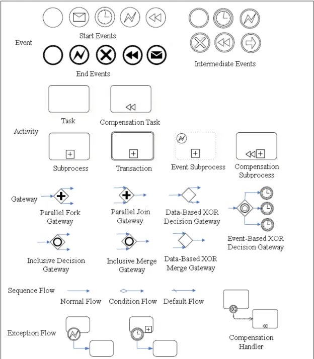
(19) 2.4 The Elements of BPMN Signature Patterns. Figure 2.2. The Core Subset of BPMN Elements. Figure 2.2 shows that the core subset of BPMN elements of constructing BPMN signature patterns.. 10.
(20) 2.5 Existing Methods to Help Develop Signature Workflows There are three methods for helping the development of signature workflows. The first two of them are based on Petri net [10] and the last work is based on XFlowML [9].. Shen [22] analyzed the structures of a signature workflow and constructed a workflow model on the basis of Petri net [10]. The signature workflow is divided into five phases: the issuing draft, the department head, the chief of office, the countersign and the executive leadership. Petri net has a great advantage to describe phenomena of conflict, synchronous, asynchronous and concurrency, etc. The second one proposes a hierarchical extension of Petri net to model the active signature workflow [15]. The approach allows the process designers to specify which activities may be refined and enables the participants of the signature workflow to modify these activities. In [9], the last defines an XML extension called XFlowML. XFlowML is an agent-based to describe signature workflows. Due to the intrinsic hierarchical notation of XFlowML, XFlowML is claimed more straightforward participants of the signature workflow than graphs.. These approaches have their own advantages. However, the advantages are neither based on BPMN nor with patterns. For example, Petri net or extension of Petri net is less powerful than BPMN. They do not support patterns either. XFlowML is claimed to be better than graphs, but the designer does not compared it with BPMN, a graphical-based modeling notation. There is no pattern for constructing signature workflow with XFlowML.. 11.
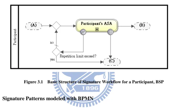
(21) Chapter 3. BPMN Signature Patterns To reduce the design work of signature workflows in WfMS, we present a set of signature patterns in WfMS with BPMN. The designer can adopt the signature patterns to fit the corresponding requirements of SMS and PMS. Signature workflows are modeled with orchestration diagram in BPMN, and the diagrams representing choreographies, collaborations or conversations are not discussed in our work. 3.1. Basic Components for Describing Signature Patterns. 3.1.1 The Format for Signature Patterns The format of our patterns is based on the format in [2] and BPMN [12] and described as follows: 1.. Name: A unified vocabulary of the pattern which increases the efficiency of the concept of communication.. 2.. Intent: A description of the behavior and the effectiveness of the pattern.. 3.. Applicability: An indication of what conditions for the use of the pattern.. 4.. Structure: A presentation of workflows of the pattern with BPMN.. 5.. Examples about how to use the pattern in real case.. 3.1.2 Basic Structure of Signature Workflow for a Participant In the thesis, a BPMN signature pattern is composed of several Structures of Signature Workflow for a Participant (SP). Besides, all the SPs are derived from the Basic Structure of Signature Workflow for a Participant (BSP). As Figure 3.1 illustrates, a BSP is composed of an ASA, several control structures, and a participant in the corresponding signature workflow. Region (A) represents the entry point of the BSP, the entry point a participant starts executing an ASA. When an ASA is successfully executed, the BSP is directed to the path leading to region (B), and region (C) otherwise. 12.
(22) An ASA might fail in the following circumstances: (1) When the participant cancels the execution or disapproves the content of his ASA. (2) When an exception occurs, the ASA would be rebooted by itself first to correct the exception. An index number is adopted to record the number of rebooting(s). When the ASA reaches its maximal limitation of rebooting number, the ASA fails.. Figure 3.1. 3.2. Basic Structure of Signature Workflow for a Participant, BSP. Signature Patterns modeled with BPMN The signature patterns are described according to the decision making modes in [7] and. our practical experiences. There are six common signature patterns derived. They are put into two categories, sequential and parallel, accordingly. Section 3.2.1 to 3.2.2 presents each of them. 3.2.1 Sequential Category Signature workflows derived from the patterns in the sequential category are composed of several ASAs which are executed sequentially. When the originator completes his/her ASA, the s-document is sent to the reviewer(s) for approval. There might be more than one reviewer, so that a reviewer might approve and send the s-document to the next or return it to the previous one or the originator. Each workflow (process) has its paths of document transfer. 13.
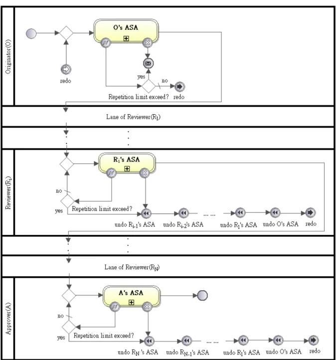
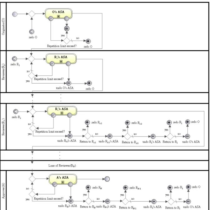
(23) There are three signature patterns identified in this category: Sequential Signature, Jump Signature, and Return Signature. 3.2.1.1 Sequential Signature Pattern The simplest signature workflow is composed of sequential participants. The process can be named as Sequential Signature pattern, and its pattern is shown below.. Figure 3.2. 1.. A Sequential Signature. Name: Sequential Signature 14.
(24) 2.. Intent: While the originator completes the corresponding ASA in a signature workflow, the s-document is sent to the reviewer(s) for approval in sequence. If reviewer(s) disagrees the content of the s-document received, the ASAs of the originator and the previous reviewers are compensated.. 3.. Applicability: This pattern is applicable for the signature workflows where the s-document is approved successively in a hierarchical organization.. 4.. Structure: Figure 3.2 illustrates the structure of Sequential Signature pattern composed of SP of the originator (OSP), SP of the first reviewer (RSP), and SP of the approver (ASP). Due to similarity and presentation space, SPs of the rest reviewer(s) are omitted. SPs shown in Figure 3.2 are introduced one by one as follows: (1) OSP includes the ASA executed by the originator in a signature workflow. The signature workflow is initialized at the entry point of OSP. Once the originator executes the ASA successfully, the s-document is sent to the first reviewer. Otherwise, when the ASA fails, a cancellation message is sent to other user(s) for notification. To simplify the flow inside OSP, a redo event including generator and catcher is defined to reboot OSP. In the later patterns a redo event might be given a name to help the description. (2) For N reviewers in a signature workflow, Ri, 1 <= i <= N, represents the ith reviewers in the signature workflow, and RSPi includes the ASA executed by Ri. The s-document approved by Ri-1 (or the originator if i = 1) is passed to Ri, and then passed to Ri+1 (or the approver if i = N) if Ri executes his ASA successfully. When the execution of Ri’s ASA fails, the s-document is returned to the originator for rebooting. The returning flow, notated as the cancellation path, includes a series of undo event(s) from Ri-1, Ri-2, ..., R1 and the originator. To keep the consistency, the order of undo events original is arranged in reverse order of execution before the s-document is returned. (3) ASP is similar to RSPk, k = N + 1. After the approver executes his ASA 15.
(25) successfully, it indicates that the signature workflow succeeds. 5.. Examples: The first example is that when a clerk of the bank completes a withdrawal job about large amounts of cash, a document associated with the details of the withdrawal job needs to be reviewed by the assistant manager. As soon as the document is approved by the assistant manager, it is sent to the manager for the final approval.. 16.
(26) 3.2.1.2 Jump Signature Pattern The advanced sequential signature workflow has the ability to handle emergencies. The process can be named as Jump Signature pattern, and its pattern is shown below.. Figure 3.3. 1.. A Jump Signature. Name: Jump Signature 17.
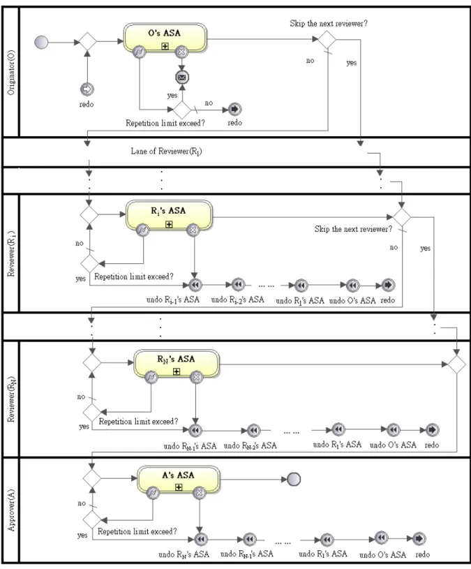
(27) 2.. Intent: This pattern is derived from Sequential Signature pattern. When an emergency occurs in a signature workflow, to reduce the signature workflow, the s-document agreement can be completed by key reviewer(s). In other words, the paths of document transfer allow the ASAs of the trivial reviewer(s) being skipped for emergency. If any key reviewer(s) disapproves the content of the s-document, the ASAs of the originator and only the previous key reviewer(s) are compensated. Especially, when all the reviewers, whose ASA’s execution time is long, can be treated as trivial reviewers, the pattern can be applied to speed up the process for emergency.. 3.. Applicability: This pattern is useful for the signature workflows where the significance of each job is various among different cases.. 4.. Structure: As Figure 3.3 illustrates, Jump Signature pattern is constructed on the basis of Sequential Signature pattern. OSP contains an extra exclusive gateway behind its ASA to check whether the next reviewer is skipped. If it is true, the s-document is sent to the similar extra exclusive gateway of next reviewer to see it is skipped, too.. Such an extra exclusive gateway is put at the same location for RSPi,. 1 <= i <= N, so that it can work the same function after completing its ASA. However, the exclusive gateway in RSPN directs the process to ASP because the approver cannot be skipped. Though Ri’s, 1 <= i <= N, cancellation path includes a series of undo event(s), only the undo event(s) of the previous key reviewer(s) and the originator works when the execution of Ri’s ASA fails. 5.. Examples: The salesman applies for an urgent tender case and the time of the case reviewed by the assistant managers is long. The application cannot be approved in time if it is reviewed by all the assistant managers as usual. According to the policy for emergent cases, he skips the assistant managers and directly sends the application to the manager for approval to catch up the deadline.. 18.
(28) 3.2.1.3 Return Signature Pattern The more complex sequential signature workflow can control the costs when the s-document is disapproved. The process can be named as Return Signature pattern, and its pattern is shown below.. Figure 3.4. A Return Signature. 1.. Name: Return Signature. 2.. Intent: Return Signature pattern is derived from Sequential Signature pattern. In the pattern, when a reviewer disapproves the content of the s-document, the s-document 19.
(29) can be sent back to one of the previous reviewer(s) or the originator directly, and the ASAs between the two reviewers are compensated only. If the chosen reviewer receives the rejected s-document, the reviewer corrects the errors and continues the signature workflow. It saves the costs of s-document cancellation and increase the flexibility for cancellation. 3.. Applicability: This pattern is applied for the signature workflows with many reviewers and costly cancellation paths.. 4.. Structure: As Figure 3.4 illustrates, Return Signature pattern is similar to Sequential Signature pattern. In RSPi, 1 <= i <= N, an exclusive gateway is added between two continuous undo events in the cancellation path. The extra exclusive gateways are responsible to choose one of the previous reviewers to send back the rejected s-document. When Rj, 0 < j < i, is chosen to receive the s-document, a pair of redo events named “redo Rj” leads the signature workflow to RSPj. Before sending back the s-document to Rj, the ASAs completed by Rj to Ri-1 are compensated in reverse order of execution. However, there are no extra exclusive gateways and redo events added in the cancellation path of RSP1 because the s-document is sent back to the originator only. ASP can be treated as RSPk , k = N + 1, and there is no redo event at the entry point because the approver is the last reviewer.. 5.. Examples: The signature workflow for examination of annual budget has ten assistant managers as reviewers. To save the cancellation costs, instead of the originator, any of the assistant managers can be chosen to revise the document when the manager disapproves the annual budget.. 20.
(30) 3.2.2 Parallel Category Our patterns in parallel category are extended from Sequential Signature pattern. After the originator completes the ASA, the s-document of the patterns is duplicated into several mv-s-documents, of which each is sent to a reviewer in parallel. To simplify our discussion, we assume that all reviewer(s) starts to execute his/her ASA at the same time. To ensure the consistency of the signature workflow, when any of the reviewers disapproves his/her mv-s-document, the rest reviewers are enforced immediately to do: the completed ASAs are compensated and the uncompleted ones are rollback. After all the mv-s-documents are reviewed, the mv-s-documents are collected at the starting subprocess of the approver. If any reviewer disapproves his/her mv-s-document, the approver asks the originator to compensate his/her ASA with the information collected and redo the whole process. Otherwise, the all the information are merged into an s-document to start the final approval.. There are three signature patterns in this category presented in the following subsections correspondingly: Static Countersignature, Dynamic Countersignature, and Additional Countersignature.. 21.
(31) 3.2.2.1 Static Countersignature Pattern The simplest parallel signature workflow is to let the reviewer keep in the process. The process can be named as Static Countersignature pattern, and its pattern is shown below.. Figure 3.5. A Static Countersignature. 1.. Name: Static Countersignature. 2.. Intent: The reviewers in this pattern cannot be removed during the signature 22.
(32) workflow. 3.. Applicability: This pattern is applicable for the signature workflows with essential reviewers approving the s-document simultaneously.. 4.. Structure: Figure 3.5 shows the structure of this pattern. In the pattern, OSP contains a parallel gateway after the ASA to dispatch the mv-s-documents to the corresponding reviewers. In RSPi, 1 <= i <= N, when the ASA fails, an undo event is thrown to the rest reviewers simultaneously for the compensation of their ASAs. ASP contains three structures described as below: (1) A parallel gateway, the entry point of ASP, is used to merge the input mv-s-documents. (2) An exclusive gateway, after the parallel gateway, checks whether any reviewer disapproves the mv-s-document. (3) An undo event generator between two parallel gateways is used to ask the compensation of Ri’s ASA, 1 <= i <= N, before OSP restarts the process again.. 5.. Examples: The human resource and the accounting department in the company are necessary departments to approve the leaving application. When an employee leaves, the human resource and the accounting department sign the leaving applications before the manager approves the application.. 23.
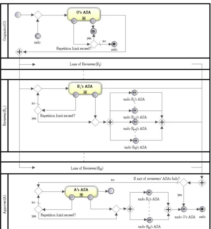
(33) 3.2.2.2 Dynamic Countersignature Pattern A parallel process can be more complicated. For example, it allows the originator to select the reviewers from all followed to approve their work after the originator’s ASA is completed. The selection at the end of its ASA occurs at the originator’s first turn or each of its redo action. Such a process can be implemented according to Dynamic Countersignature pattern shown below.. Figure 3.6. A Dynamic Countersignature. 1.. Name: Dynamic Countersignature. 2.. Intent: Dynamic Countersignature pattern, an extension of Static Countersignature 24.
(34) pattern, allows the originator to determine the necessary reviewer(s) after completing its ASA. Besides, the originator may ignore all the reviewers and send the s-document directly to the approver. 3.. Applicability: During design time, the designers may be allowed to put all possible reviewers in the parallel signature workflow only.. This pattern can be applied to. implement the corresponding workflow. 4.. Structure: As in Figure 3.6, the pattern is similar to Static Signature pattern. In the pattern, after the originator completes his/her ASA, an inclusive gateway in OSP duplicates and dispatches the mv-s-documents to the necessary reviewers. The input mv-s-documents of ASP are merged by an inclusive gateway after all the reviewers review the mv-s-documents. Besides, a flow connecting the two inclusive gateways is established that the originator may pass the s-document to the approver directly if it is unnecessary being reviewed.. 5.. Examples: When the cost of an advertising application exceeds the budget cap, the sales department may determine either or both of auditing department and accounting department needed to approve the application before the approved of the manager. When the cost is low, the sales department may send the application directly to the manager for approval.. 25.
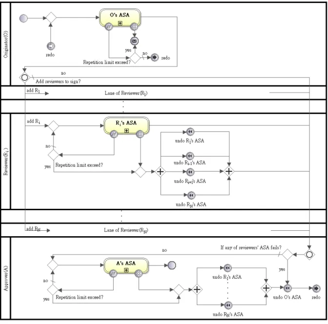
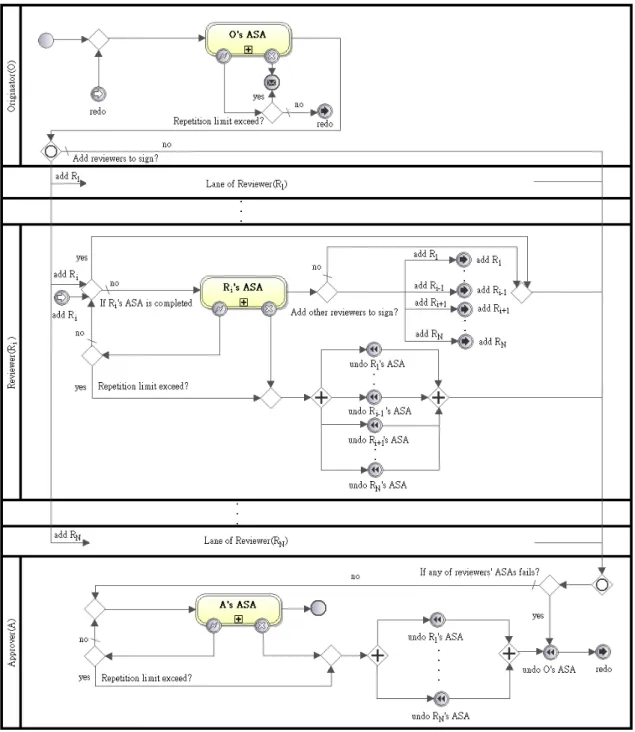
(35) 3.2.2.3 Additional Countersignature Pattern A more complicated case is that the system allows a reviewer to ask another reviewer to approve the corresponding review after his approval. The target reviewer of each one is selected during program execution. The following pattern, Additional Countersignature pattern, contains a sample structure.. Figure 3.7. 1.. An Additional Countersignature. Name: Additional Countersignature 26.
(36) 2.. Intent: Additional Countersignature pattern is an extension of Dynamic Countersignature pattern. Due to the sequence of invocations from a predefined reviewer and a reviewer by another one, a sequence of reviewers and their approval work is generated. There may be more than one sequence of reviewers, but a reviewer cannot perform the review work more than one time.. 3.. Applicability: This pattern is applicable for the signature workflows where both the originator and the reviewer(s) are allowed to determine the necessary reviewer(s) according to the characteristic of the job dynamically.. 4.. Structure: Figure 3.7 shows that Additional Countersignature pattern is constructed from Dynamic Signature pattern. To improve the flexibility of reviewer decision, there are three control structures added to RSPi, 1 <= i <= N: (1) A condition is added to the exclusive gateway in front of Ri’s ASA to check whether the ASA is completed. If it is true, Ri’s ASA is skipped to avoid duplicated approval. Otherwise, Ri’s ASA is normally executed. (2) An exclusive gateway after Ri’s ASA is added to allow Ri to invoke another one to approve the mv-s-document. (3) A redo event including generator and catcher is named “add Rj”, 1 <= j <= N and i ≠ j, to direct the flow to RSPj if Ri invokes Rj to approve the mv-s-document.. 5.. Examples: The HR department, the accounting department, and the risk management department are the potential reviewers of investment application. When the investment department proposes an application associated with investments, they decide that the HR department and the accounting department should review the application. If HR department cannot distinguish whether the application may bring damages, it can request the risk management department as an additional reviewer. If the damage is simple and can be decided by HR department, such a request is not needed. Additional Countersignature pattern works for this case.. 27.
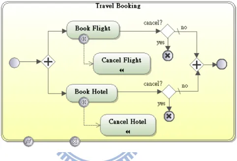
(37) Chapter 4. Transaction Modulation Method BPMN signature patterns can help to design signature workflows in WfMS, by simplifying the consideration of relationships between ASAs in a signature workflow. However, modeling the ASAs with BPMN transaction is an annoying task for the designers because they need to add extra notations to present the completed meanings of BPMN transaction.. Figure 4.1. A BPMN Transaction for Travel Booking. For example, Figure 4.1 indicates an example with BPMN for travel booking. The designer needs to model two cancel end events and two compensation handlers because a booking transaction allows the traveler to cancel the reserved flight or hotel before it completes. The rules of BPMN itself make the introduction of these events and handlers to be annoying when modeling the transactions, so that a designer may forget part of the works. To reduce the works of modeling transactions, we propose TM method to help the designer to transform BPMN processes defined into BPMN transactions. Besides, our works are focused on well-formed core BPMN processes [1][21] only.. Section 4.1 presents the method and section 4.2 provides an example to illustrate how to work with the method. 28.
(38) 4.1. Details of our Transaction Modulation Method Our TM method contains the following five steps in sequence. 1.. Transform each process defined into a transaction, and attach an error intermediate event and a cancel intermediate event to the boundary of the transaction.. 2.. Append an exclusive gateway and a cancel end event on each sequence flow, in all transactions.. 3.. Append a compensation handler to all activities that do not have such a handler, in all transactions.. 4.. Add an independent timer event subprocess and an independent conditional event subprocess in each transaction, where the end of the timer event subprocess throws an error end event and the end of the conditional event subprocess throws a cancel end event.. 5.. Add an independent error event subprocess and an independent compensation event subprocess to indicate the compensation event for each activity in each transaction. The compensation events are given in the reverse order of the activities; each split and merged flow in the compensation flows is connected with a parallel gateway. The end of the error event subprocess throws an error end event and the end of the compensation event subprocess throws a none end event.. The first step of the method is to transform a BPMN process defined into a BPMN transaction because the activities of the process are atomic. The transformed transaction is viewed as an ACID transaction. To improve the capability of event handling of the transaction, an error and a cancel intermediate event are attached to the boundary of the transaction after the transformation is completed.. The next step of the method is to add cancel end events to the transaction because the transaction allows the participant to cancel its execution. When a cancel end event is thrown 29.
(39) from a transaction, the execution of transaction is interrupted. Besides, the completed activities of the transaction are compensated and the incomplete ones are rollback. To allow the participant to cancel the transaction at any time, an exclusive gateway and a cancel end event are appended to each sequence flow in the transaction to check whether the cancel end event is thrown or not.. The third step of the method is to add a compensation handler for each activity in the transaction. A compensation handler is responsible to compensate the original activity when catching the compensation event [12]. The compensation handler of each activity in the transaction makes the compensation process of the transaction to be clearer. Therefore, such a compensation handler is appended to each activity in the transaction in our method. Table 4.1 presents the rules of the step according to original activities. Table 4.1. The Rules of Adding Compensation Handlers. Contents. Original Activity. Result of the implementation. Activity Type. (1)Task. (2)Subprocess. 30.
(40) (3)Event handler. (4)Compensatio n handler. (5)Transaction. Table 4.1 shows that a compensation handler is appended to the original activity except for the rule (4) because it is added already in previous step. In rule (3) and (5), the compensation handler is appended to an event handler besides the original activity.. The fourth step adds two event subprocesses in the transaction for improving the capability of event handling of the transaction. These two processes are of predefined structure and defined as: 1.. The timer event subprocess, responsible to direct the process to the error handling flow, defined in the next step, when the transaction is time-out. 31.
(41) 2.. The conditional event subprocess, canceling the execution of the activities in the transaction when an interrupted event occurs outside of the transaction. For example, when the other parallel ASA is canceled, an interrupted event is thrown away.. The last step adds two additional event subprocesses in the transaction. The activities and their flow inside both subprocesses are defined based on the workflow in the transaction, furthermore: 1.. The error event subprocess, responsible to invoke a series of compensation activities when a hazard occurs in the transaction. After the compensation is completed, the event subprocess generates an error event to direct the flow to the error catcher attached to the boundary of the transaction.. 2.. The compensation event subprocess, a callback function for invoking a series of compensation activities when the corresponding compensation event is thrown away. When the compensation of the transaction is completed, the compensation event generator outside of the transaction continues the process.. BPMN [12] declares that both processes are not necessary. However, to make the structure more clearly, we ask designer to fulfill the step. Table 4.2. The Rules of Constructing the Executive Order of Compensation Activities. Contents. The executive order The executive order of original activities. Flow Type. of compensation activities. (1) Sequence. 32.
(42) (2)XOR-Split. (3)XOR-Join. (4)AND-Split. (5)AND-Join. 33.
(43) (6)OR-Split. (7)OR-Join. (8)Event-Based XOR-Split. (9)Event Handler. Table 4.2 presents nine rules for constructing the executive order of compensation activities according to the control nodes in [12]. The execution order of compensation activities is the reverse of execution of the original activities in the transaction. To simplify the construction, when the original workflow has a split control node, a join node is adopted to merge the corresponding compensation flows. The all compensation activities are invoked but only the completed activities can be compensated. The rules of constructing compensation 34.
(44) flows are classified as three categories: 1.. Sequence: In the rule (1), when the flows of activities are sequence, the executive order of compensation flows is constructed.. 2.. Split flows: In rule (3), (5) and (7), when the flows of activities are merged, the split compensation flows are constructed.. 3.. Merged flows: In the rule (2), (4), (6), (8) and (9), the compensation flows are merged because the flows of activities are diverged.. 4.2. An Example of Adopting Transaction Modulation Method To illustrate each step of the method, we provide an example adopting the method. Figure 4.2 depicts the initial state of the example including a start event, an end event and two tasks sequentially executed.. Figure 4.2. The Initial State of an Example. The first step of the method is to transform a process into a transaction. As in Figure 4.3, the transformed transaction is an ACID transaction, i.e. Task1 and Task2 in the transaction are not separated further.. Figure 4.3. The Example of Transforming a Process into a Transaction. The second step is to append an exclusive gateway and a cancel end event to each 35.
(45) sequence flow. As in Figure 4.4, three cancel end events and exclusive gateways are appended to allow the participant to cancel the transaction when: (1) before Task1 is executed, (2) between Task1 and Task2, or (3) after Task2 is executed.. Figure 4.4. The Example of Adding Cancel End Events. The third step is to append a compensation handler to each activity. Figure 4.5 shows that two compensation handlers are appended to the original activities respectively. The Cancel Task1 and Cancel Task2 are responsible to compensate Task1 and Task2 respectively when compensation event occurs.. Figure 4.5. The Example of Adding Compensation Handlers. The fourth step is to add two static event subprocesses to the transaction. Figure 4.6 illustrates that a timer and a conditional event subprocesses are added for improving the capability of handling timer and interrupted events.. 36.
(46) Figure 4.6. The Example of Adding Static Event Subprocesses. The final step is to add two dynamic event subprocesses to the transaction. Figure 4.7 shows the compensation events inside the two event subprocesses are in reverse of Task1 and Task2. Therefore, the event / compensation handler can be performed in correct order.. Figure 4.7. The Example of Adding Dynamic Event Subprocesses. 37.
(47) Chapter 5. A Methodology for Modeling Signature Workflows We propose a methodology to model signature workflows on the basis of the patterns and TM method described in previous chapters. Section 5.1 sketches the methodology and section 5.2 presents a case study to illustrate the methodology. 5.1. The Guideline of the Methodology The procedure of the methodology can be divided into five steps as below: (1) Choose the corresponding BPMN signature pattern according to the requirements. (2) Adjust the number of RSPs in the chosen BPMN signature pattern according to the actual organizations of the requirements, manually. (3) Separately design the well-formed core BPMN process for each participant in the signature workflow. (4) Transform BPMN processes into BPMN transactions via TM method. (5) Fill all the ASAs in the adjusted pattern with the transformed transactions according to the corresponding participants.. With the methodology, the patterns can be used to simplify the design of the signature workflow. Besides, deferred consideration of the non-signature functions due to TM method can simplify the design of ASAs. 5.2. Case Study To demonstrate the methodology proposed in Section 5.1, a resignation process is. established as an example in this section. The resignation processes are executed in sequence and the participants of the resignation process are composed of an employee, a manager and a boss. The employee in the process has three sequential tasks. Before he applies for leaving, he needs to terminate his current tasks and returns the public assets to his company. When his manager receives the resignation, the first task of the manager is to verify the resignation. Simultaneously, to reduce the influence of the resignation, the manager assigns an agent to 38.
(48) substitute for the applicant and revises the original schedule. The boss is the final participant of the process. When the application is verified by the boss, to continue the business of the corporation, he looks for the new employees or revises the business objective according to the development policy of the company, and sums up the total salary of the company finally.. The example process is an example of Sequential Signature pattern. Therefore, the process designer simply adopts the Sequential Signature pattern as the skeleton of the process and modifies the structure of the pattern to fit the participants of the example. Next, he designs the BPMN process for each participant in the example. The designed processes are shown from Figure 5.1 to Figure 5.3, respectively.. Figure 5.1. The Tasks of the Employee in Resignation Process. Figure 5.1 illustrates that there are three sequential tasks in the employee’s process. They are Handover Works, Return Computer and Apply For leave tasks.. Figure 5.2. The Tasks of the Manager in Resignation Process. Figure 5.2 illustrates that after the manager verifies the application, Assign Resource and Revise Schedule tasks are executed in parallel simultaneously.. 39.
(49) Figure 5.3. The Tasks of the Boss in Resignation Process. Figure 5.3 illustrates that the first task of the boss’s process is to verify the application. After Verification task is executed, either Arrange Resource task or Adjust Objective task is executed. Finally, Calculate Salary task is executed when the alternative task is completed.. The next step of the methodology is to transform the initial BPMN processes into the BPMN transactions via TM method. The transformed results are shown from Figure 5.4 to Figure 5.6, respectively.. Figure 5.4. The Transformed Transaction of the Employee. Figure 5.4 illustrates that the BPMN process of the employee is transformed into BPMN transaction. The compensation handlers in the compensation flow are executed in reverse sequence because the tasks of the employee are sequentially executed.. 40.
(50) Figure 5.5. The Transformed Transaction of the Manager. Figure 5.5 shows the result of the transformed transaction of the manager. Cancel Assignation and Cancel Revisal tasks in compensation flow are simultaneously executed and Cancel Verification task is then executed.. Figure 5.6. The Transformed Transaction of the Boss. Figure 5.6 shows the result of the transformed transaction of the boss. In the compensation flow, Cancel Calculation task is executed first and Cancel Arrangement and 41.
(51) Cancel Adjustment tasks are then executed simultaneously. Finally, Cancel Verification task is executed.. The final step of the methodology is to fill the ASAs of the adjusted diagram with the corresponding transactions. After the step, the completed diagram of the resignation process is presented in Figure 5.7.. Figure 5.7. The Final Diagram of the Resignation Process. 42.
(52) Chapter 6. Conclusion and Future Works In this thesis, a methodology based on BPMN patterns is proposed to reduce the design efforts of signature workflows. There are six BPMN signature patterns constructed by us to display the basic workflow structures for various signature semantics. The patterns can be viewed as a united glossary which is helpful in reducing the communication costs between designers. To improve the design process further, TM method is applied to help transform BPMN processes into BPMN transactions. Process designers can postpone and thus simplify the specification for the design works of the participants in the signature workflow. An example is introduced to indicate the contribution expected.. Compared with the approaches in Section 2.5, our methodology is better for providing patterns and delaying some works which are not the signature function based on BPMN. However, although we have described six patterns for the requirements of the signatures within WfMS, the patterns are not enough and need be constructed further. For example, the categories of signature patterns may be enriched, and countersignature patterns need to be designed for the compensation in the signature workflow which is not executed unsuccessfully. On the other hand, each of our patterns matches a single requirement only and the patterns may be combined to match the sophisticated requirement such as jump countersignature, etc. Besides, the specification need be transformed into WS-BPEL [11] for execution.. 43.
(53) Reference [1] Dijkman, R. M., Dumas, M. and Ouyang, C., “Formal Semantics and Analysis of BPMN Process Models,” Information and Software Technology, 2009. [2] Gamma, E., Johnson, R., Vlissides, J. and et al., "Design Patterns: Elements of Reusable Object-Oriented Software," Addison-Wesley, 1994. [3] Kous, K., "Comparative Analysis Versions of BPMN and its Support with Control-flow Patterns," MIPRO, 2010 Proceedings of the 33rd International Convention, 2010, pp. pp.315-319. [4] Lerner, B. S., Christov, S., Osterweil, L. J. and et al., “Exception Handling Patterns for Process Modeling,” IEEE Transactions on Software Engineering, vol. 36, no. 2, pp. 162-183, Mar-Apr, 2010. [5] Leung, K. R.P.H. and Hui, L. C.K., “Signature Management in Workflow Systems,” Proceedings.. Twenty-Third. Annual. International. Computer. Software. and. Applications Conference, pp. 424-429, 1999. [6] Leung, K. R.P.H. and Hui L. C.K., “Multiple Signature Handling in Workflow Systems,” Proceedings of the 33rd Annual Hawaii International Conference on System Sciences, 2000. [7] Leung, K. R.P.H. and Hui, L. C.K., “Handling Signature Purposes in Workflow Systems,” Journal of Systems and Software, vol. 55, no. 3, pp. 245-259, Jan, 2001. [8] Liu, J.B., Qiu, Z.L., Zhou, H. and et al., “A Schema for Multi-Signature Handling Based on Workflow Model,” 2009 Fifth International Conference on Intelligent Information Hiding and Multimedia Signal Processing, pp. 378-381, Sep. 2009. [9] Marchetti, A., Tesconi, M. and Minutoli, S., “XFlow: An XML-Based Document-Centric Workflow,” Web Information Systems Engineering - Wise 2005, vol. 3806, pp. 290-303, 2005. [10] Murata, T., “Petri Nets - Properties, Analysis and Applications,” Proceedings of the IEEE, vol. 77, no. 4, pp. 541-580, Apr, 1989. 44.
(54) [11] OASIS, "Web Services Business Process Execution Language Version 2.0," OASIS Standard, 2007. [12] Object Management Group, “Business Process Model and Notation Version 2.0,” OMG Final Adopted Specification. Object Management Group, January. 2011. [13] Object Management Group, http://www.omg.org/ [14] Rosa, M. L., Reijers, H. A., Van Der Aalst, W. M.P. and et al., “APROMORE: An Advanced Process Model Repository,” 2010. [15] Stork, D. G. and Glabbeek, R. V., “Token-Controlled Place Refinement in Hierarchical Petri Nets with Application to Active Document Workflow,” Applications and Theory of Petri Nets 2002, vol. 2360, pp. 394-413, 2002. [16] Takemura, T., “Formal Semantics and Verification of BPMN Transaction and Compensation,” Los Alamitos: IEEE Computer Soc, 2008. [17] The Workflow Management Coalition, “Terminology & Glossary,” Management, no. 3. pp. 1-65, 1999. [18] Wang, T., Vonk, J., Kratz, B. and et al., “A Survey on the History of Transaction Management: From Flat to Grid Transactions,” Distributed and Parallel Databases, vol. 23, no. 3, pp. 235-270, Jun, 2008. [19] Wohed, P., Van Der Aalst, W. M.P., Dumas, M. and et al., “Pattern-based Analysis of BPMN,” Technology, 2005. [20] Wu, Y., “Efficient Authentication of Electronic Document Workflow,” Information Security and Cryptology, Proceedings, vol. 3822, pp. 101-112, 2005. [21] Ye, J.H., Sun, S.X., Wen, L. and et al., “Transformation of BPMN to YAWL,” 2008 International Conference on Computer Science and Software Engineering, pp. 354-359, 2008. [22] Shen, Z. and Wang, H., “Research on the Application of Workflow Technology in OA System,” in Computer Science and Information Technology, 2010 3rd IEEE International Conference on, 2010, vol. 7, pp. 519–522.. 45.
(55)
數據
![Figure 2.1 The Execution Semantics of Transaction in BPMN [12]](https://thumb-ap.123doks.com/thumbv2/9libinfo/8021034.160811/18.892.305.670.799.989/figure-execution-semantics-transaction-bpmn.webp)
+7
相關文件
In the algorithm, the cell averages in the resulting slightly non-uniform grid is updated by employing a finite volume method based on a wave- propagation formulation, which is very
• 點選 Method Editor 來進行方法程式編輯(同樣,也可 在開啟後的視窗中,點選 Form Editor 來切回原視窗). Form
As with all poetry, is-poems are a little more complicated than it looks. You need to write down all your associations and ideas and then just select a few, adding the
Lemma 4.5.. Then, the proof is complete.. By Theorem 4.1 and Theorem 4.6, the conclusion is drawn. Baes, Convexity and differentiability properties of spectral functions and
• Compare ρESDP as solved by LPCGD method with ESDP as solved by Sedumi 1.05 Sturm (with the interface to Sedumi coded by Wang et al )... Left: Soln of ρESDP found by
樣本重抽法 (resampling method) 則是一個與實際抽樣分配或是 大樣本漸近分配完全迥異的做法 , 其統計推論的基礎 , 來自 「原有樣
溫度轉換 自行設計 溫度轉換 自行設計 統計程式 簡單 簡單 統計程式.
This research is focused on the integration of test theory, item response theory (IRT), network technology, and database management into an online adaptive test system developed
