國
立
交
通
大
學
資訊科學與工程研究所
碩
士
論
文
一個在同儕網路下有效率的網路電視傳輸方式
An Efficient P2P IPTV Transmission Scheme
under NAT Architecture
研 究 生:陳閔煌
指導教授:陳耀宗 教授
許騰尹 教授
一個在同儕網路下有效率的網路電視傳輸方式
An Efficient P2P IPTV Transmission Scheme
under NAT Architecture
研 究 生:陳閔煌 Student:Ming-Huang Chen
指導教授:陳耀宗 Advisor:Yaw-Chung Chen
許騰尹
Terng-Tin Hsu
國 立 交 通 大 學
資訊科學與工程研究所
碩 士 論 文
A ThesisSubmitted to Institute of Computer Science and Engineering College of Computer Science
National Chiao Tung University in partial Fulfillment of the Requirements
for the Degree of Master
in
Computer Science
July 2011
Hsinchu, Taiwan, Republic of China
中華民國一百年七月
i
一個在同儕網路下有效率的網路電視傳輸方式
學生:陳閔煌
指導教授:陳耀宗 博士
許騰尹 博士
國立交通大學資訊科學與工程研究所
摘要
IPTV ( 網路電視 ) 是一個新興的網路應用程式,並且因為其資
料傳輸量大的關係,也替 ISP ( Internet Service Provider) 的骨幹網路
帶來十分大量的資料流量。另外,許多基於同儕網路架構的網路電視
已經有成功的普及。迄今,基於同儕網路架構的網路電視主要有兩種
架構:
”Tree – Push” 以及 “Mesh – Pull”。其中又以“Mesh – Pull”的方
式最為普遍。另外,由於多媒體群體廣播架構的推廣緩慢,導致現行
的網路電視架構占據了很大部分的網路頻寬。因此,本論文提出了一
個方法,能夠在現行的網路架構底下,在不對任何的實體網路設備做
修改的前提下,能夠大幅的節省網路頻寬,以及提高網路電視的播放
品質。
ii
An Efficient P2P IPTV Transmission
Scheme under NAT Architecture
Student:Ming-Huang Chen
Advisor:Dr. Yaw-Chung Chen
Dr. Terng-Ying Hsu
Institute of Computer Science and Engineering
National Chiao Tung University
Abstract
An emerging Internet application, IPTV, has the potential to flood Internet access network and backbone ISPs with massive amount of multimedia traffic. Although many architectures are available for IPTV video distribution, several mesh-pull P2P architectures have been successfully deployed on the Internet. Nowadays, IPTV over P2P streaming networks has advanced significantly using two different approaches: tree-push versus mesh-pull. In particular, the mesh-pull streaming approach has achieved a number of successful commercial deployments. Thanks to slow deployment of multicast deployment, IPTV streaming traffic overwhelms the internet. We proposed a novel IPTV and P2P-IPTV transmission scheme that allows server transmit single connection instead of multiple connection, which saves bandwidth and also increase IPTV broadcasting quality.
iii
Acknowledgement
這篇論文的完成,首先要感謝我的指導老師陳耀宗教授,老師在研究上的指 導讓我獲益良多,除了學術上的指導以及研究上的訓練之外,老師在為人處事方 面,也是我的典範。同時感謝詹家泰教授,劉忠賢教授與李春良教授在口試時給 予意見,使論文更加的完整。 接著要感謝實驗室的阿華學長、小郭學長,兩位學長在我研究上遇到瓶頸, 以及論文撰寫的技巧方面,皆不吝地給予我許多的指點,使我的論文得以順利地 完成。同時要感謝姚姚及阿慶兩位同學,在生活以及研究上,互相的砥礪加油打 氣,使我的研究所生活過得精采許多。也要感謝實驗室其他一起成長的夥伴們, 陪我度過這飛快的兩年。 此外我要感謝涵茵以及阿尼狗,還有我的朋友們明峰、宏郁、晟廷、暐強、 書華、梓喬、小田、俊瑋等,讓我的生活增添了許許多多珍貴的回憶。最後我還 要感謝我的家人,謝謝他們一路上的支持,他們是我最大的動力及支柱。iv
Content
摘要... i Abstract ... ii Content ... iv Table List ... v Figure List ... vi Chapter 1 Introduction ... 1 Chapter 2 Background ... 3 2.1 IPTV ... 3 2.2 Multicast ... 42.3 IPTV over P2P networks ... 6
2.4 Tree Push versus Mesh Pull ... 8
2.5 Network Address translation... 9
Chapter 3 The proposed scheme ... 11
3.1 Peer joins ... 13 3.1.1 Single peer ... 14 3.1.2 Multiple peers ... 15 3.2 System Process... 17 3.3 Peers Leaving ... 21 3.4 Message Format ... 22
3.5 IPTV over Peer to Peer network ... 27
Chapter 4 Implementation and Experiment ... 31
4.1 Implementation ... 31
4.2 Experiment setup and Numerical Analysis ... 37
4.2.1 Experiment Setup ... 37
4.2.2 Bandwidth Analysis ... 38
4.2.3 Startup delay Analysis ... 40
4.2.4 P2P-IPTV scale Analysis ... 42
v
Table List
vi
Figure List
Figure 2.1 IPTV Architecture... 4
Figure 2.2 Multicast illustrations ... 5
Figure 2.3 Tree push topology ... 7
Figure 2.3 Mesh pull topology ... 7
Figure 3.1 Traditional P2P network behind NAT ... 11
Figure 3.2 NAT Mapping Table ... 12
Figure 3.4 Single Client message flow ... 15
Figure 3.5 Multiple Clients message flow ... 16
Figure 3.6 System Process flowcharts ... 17
Figure 3.7 Pseudo Header ... 18
Figure 3.8 Data flows of proposed scheme ... 19
Figure 3.9 peer sniffing packets in the LAN ... 20
Figure 3.10 the proposed scheme message format ... 24
Figure 3.11 TTL subtracts while passing the network device ... 26
Figure3.12 P2P-IPTV architecture ... 27
Figure3.13 The proposed P2P-IPTV scheme ... 28
Figure3.14 Tracker server assigns source peer to other peers individually ... 29
Figure 3.15 Message flow of proposed P2P- IPTV scheme. ... 30
Figure 4.1 Program function flowcharts ... 32
Figure 4.2 Memory allocation of big-endian and little-endian ... 33
Figure 4.3 Network topology of implemented scheme ... 34
Figure 4.4 Packet sent from server to superpeer ... 35
Figure 4.5 Packet sent from superpeer to ordinary peers ... 36
vii
Figure 4.7 Tradition IPTV Client-Server transmission schemes ... 38
Figure 4.8 the proposed transmission scheme ... 39
Figure 4.9 Startup delay of traditional IPTV framework ... 41
1
Chapter 1
Introduction
Internet Protocol television (IPTV) is a system through which Internet television services are delivered using the architecture and networking methods of the Internet Protocol Suite over a packet-switched network infrastructure. Internet Protocol television (IPTV) provides digital television services over Internet Protocol (IP) for residential and business users at a lower cost. These IPTV services include commercial grade multicasting TV, video on demand (VoD), triple play, voice over IP (VoIP), and Web/email access, well beyond traditional cable television services. IPTV is a convergence of communication, computing, and content, as well as an integration of broadcasting and telecommunication.
IPTV system requires a video streaming server provides video content to clients. Large bandwidth is needed for streaming server due to heavy load of streaming flows. Thus, a large scale transmission scheme, Peer to Peer (P2P) network is applied to IPTV. Peer-to-peer (P2P) networks have been adopted for Internet live video-streaming service, and several practical systems have been deployed in past years due to the inherent scalability and ease of deployment. The successes of P2P file sharing and VoIP applications have proved that the P2P paradigm is an efficient solution to deliver all kinds of content over the Internet.
2
the single point of failure that can be inherent in a client-server based system. Nowadays, there are P2P video live streaming applications (P2P IPTV) that have been successfully deployed on the Internet. In these P2P systems, data are divided into chunks and each peer exchanges with other peers’ information about the chunks they have. Then each peer is able to download data chunks from several peers concurrently.
Since the streaming data is heavy, there exists a protocol for IPTV related transmission in Internet Protocol Suite, which called Multicast. In computer networking, multicast is the delivery of a message or information to a group of destination computers simultaneously in a single transmission from the source creating copies automatically in other network elements, such as routers, only when the topology of the network requires it. Multicast is most commonly implemented in IP multicast, which is often employed in Internet Protocol (IP) applications of streaming media and Internet television. In IP multicast the implementation of the multicast concept occurs at the IP routing level, where routers create optimal distribution paths for datagrams sent to a multicast destination address. However, there are several difficulties on multicast deployment. Thus, it is not yet possible to make fully-general multicast applications practical.
Furthermore, NAT (network address translation) devices are widely used in current network environment due to the IPv4 address space exhaustion. Network address translation (NAT) is the process of modifying IP address information in IP packet headers while in transit across a traffic routing device.
In this thesis, we proposed an IPTV and P2P-IPTV transmission strategy under NAT architecture that can save lots of network bandwidth as IP multicast does. Server transmits one copy of data instead of duplicate packets under some circumstances, which saves lots of bandwidth and increase performance of IPTV/P2P-IPTV. In addition, one major advantage is that we don’t need to modify any physical devices in our proposed scheme.
3
Chapter 2
Background
In this chapter, we briefly describe the IPTV and P2P-IPTV evolutionary process and Multicast deployment issues, focusing on those characteristics that are related to this thesis. Next, we describe the P2P-IPTV, which suddenly appear on the horizon, and several numerical analysis of popular P2P-IPTV system.
2.1 IPTV
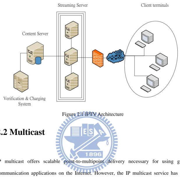
Internet Protocol television (IPTV) is a system through which Internet television services are delivered using the architecture and networking methods of the Internet Protocol Suite over a packet-switched network infrastructure, e.g., the Internet and broadband Internet access networks, instead of being delivered through traditional radio frequency broadcast, satellite signal, and cable television formats.
IPTV can be divided in to three main groups, live television, time-shifted television and VOD. In this thesis, live television is our main focus for our proposed scheme. Figure 2.1 shows the IPTV system architecture.
4
Content Server
Verification & Charging System
Streaming Server Client terminals
Figure 2.1 IPTV Architecture
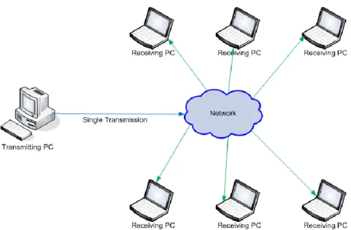
2.2 Multicast
IP multicast offers scalable point-to-multipoint delivery necessary for using group communication applications on the Internet. However, the IP multicast service has seen slow commercial deployment by ISPs and carriers. The original service model was designed without a clear understanding of commercial requirements or a robust implementation strategy. The very limited number of applications and the complexity of the architectural design, which we believe is a consequence of the open service model, have deterred widespread deployment as well.
5
Figure 2.2 Multicast illustrations
IP-based networks offer point-to-multipoint and multipoint to multipoint best-effort delivery of datagram by means of the IP-multicast service and architecture. The current service model in IP-multicast was defined without a commercial service explicitly in mind, which is one possible reason for its slow deployment. Furthermore, the current IP-multicast architecture deployed by carriers and Internet Service Providers (ISPs) to compensate for these issues is complex and has limited scalability. Trying to generalize and commercialize multicast from the current service model and protocol architecture is difficult, and in the worst case, adversely impacts the long-term success of multicast. Multicast is included with the standard set of protocols shipped with most commercial routers, but most IP carriers have not yet enabled the service in their networks. A number of issues have stalled the widespread use of multicast.
One reason for the stalled deployment is that because of older hardware generally does not support multicast. When there are no offered software upgrades, the routers are forced into early retirement. Companies rely on the depreciation of their hardware’s value in their business models. Router migration has another implication for multicast architecture
6
designs. New routers that are deployed in the backbone are generally less intelligent routers, lacking complicated services such as congestion and admission control. Routers that are simple and unintelligent can handle higher capacity traffic more efficiently. Therefore, complex services, like multicast, would be better deployed in the edge routers, except that replacing such routers upsets the business model. Therefore, both backbone routers and edge routers resist multicast deployment.
Multicast is currently a service that reduces the amount of bandwidth required to transport data to multiple recipients. Longer term, it may also be used to minimize network delays in interactive application sessions. Multicast services are currently significantly more expensive than the unicast service, in terms of deployment, installation at customer premises, and management. Consequently, multicast makes sense today for an ISP or corporate customer only when the bandwidth savings are higher than the deployment and management costs. Unicast is represented as an increasing straight line because each new receiver adds a new cost (mostly network cost). Multicast however has a high initial cost which is higher than unicast. But the cost of adding new receivers should not be as costly to support as in the unicast case. Multicast related issues are referred in [1], [2], and [3].
2.3 IPTV over P2P networks
With the rapid development of network technology, peer-to-peer (P2P) applications have become more popular among users and bring about huge traffic in the Internet world. P2P technology is to establish a peer to peer connected architecture, making each peer a client and meanwhile a server. Peers transmit their available content to their connected peers by contributing their resource (mainly upload bandwidth), thereby reducing the workload of the server. P2P technology does not need any support from the network, so it is easy to
7
deploy and cost-effective.
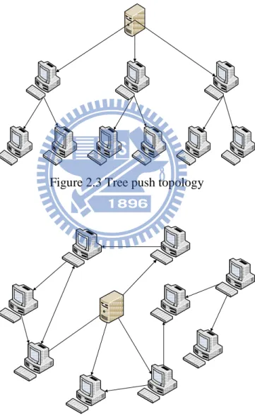
Due to the slowly deployment of Multicast, unicast transmission has become the mainstream. Moreover, IPTV also has the potential to overwhelm the Internet backbone and access networks with traffic. To date, IPTV over P2P streaming networks has advanced significantly using two different approaches: tree-push versus mesh-pull. Figure 2.3 and 2.4 shows these two architectures respectively.
Figure 2.3 Tree push topology
8
2.4 Tree Push versus Mesh Pull
In [4], it provides an overview of the general mesh-pull streaming architecture and review various challenges, design issues, and interesting research problems in this approach. [4] Outline a measurement technique for monitoring the video playback quality of mesh-pull streaming systems.
The tree-based multimedia streaming system is vulnerable to peer churn, where means very high-fluctuated peer arrival rate and leave rate. [5] propose a mesh-based multimedia streaming system to reduce the influence of peer churn and implement hybrid push and pull mechanisms to reduce the control messages and the round-trip delay between requests and responses.
Study in [6] presents our experience on a practical P2P-based live video streaming system called GridMedia, which was employed to broadcast live the Chinese Spring Festival Gala show over the Internet. Benefiting from two sets of flush-crowd traces with about 15,239 and 224,453 concurrent users in a 300 kb/s streaming session in 2005 and 2006, in [6] it performs a trace study to understand the service capacity, quality of streaming service, connection heterogeneity, user geographic distribution, and request and online duration characteristics.
In [7] , author has undertaken an in-depth measurement study of one of the most popular IPTV systems, namely, PPLive. It has developed a dedicated PPLive crawler, which enables us to study the global characteristics of the mesh-pull PPLive system. It has also collected extensive packet traces for various different measurement scenarios,
9
including both campus access networks and residential access networks. The measurement results obtained through these platforms bring important insights into P2P IPTV systems. From [7], we also obtain some numerical data (e.g. buffer size, startup delay, video bit rate, etc) for our later experiment in this thesis.
In [8], during the 2006 FIFA World Cup, we performed an extensive measurement campaign. During this worldwide event, we measured network traffic generated by the most common P2P IPTV applications, namely PPLive, PPStream, SOPCast and TVAnts. In [8] it shows that all these applications generate different traffic patterns and use different underlying mechanisms. Each application has its own download policy and maintains a different set of peers. From the traces [8] collected, it extracts several statistics, which help in having a better understanding of the behavior of P2P IPTV systems. IPTV related works are referred in [9], [10] and [11].
2.5 Network Address translation
NAT maps IP address from one domain to another, usually from private-use range to public IP. It is usually as a solution to save IPv4 address. The NAT serves N internal hosts and maintains a public IP pool which contains M IP addresses. The N hosts seldom get online concurrently so the number of M is usually less than N. When an internal node starts a connection, NAT picks an IP address from the pool and assign it to the host and all the further connection for the same host. When the internal host shutdown or does not communicate with external host for a while, the mapping will expire and the assigned public IP will be returned to the pool.
10
public IP address is allowed, mapping several private IP addresses into a single one might cause L4 port conflict and makes the upper layer connection broken. Port Address Translation (PAT) is introduced which will also translate L4 port number to avoid this problem. PAT is a kind of extension of NAT and the translation table is larger than NAT and operation is more complex. In the following sections, we use the term “NAT” to stand for PAT.
11
Chapter 3
The Proposed Scheme
In this chapter, we proposed a novel IPTV video chunk transmission scheme which can be applied to current network architecture without modifying any physical devices in Internet infrastructure. While multiple peers behind same NAT are connecting to the streaming server as in Figure 3.1, the streaming server should be aware of this kind of event.
Internet Streaming Server
Figure 3.1 Traditional P2P network behind NAT
12
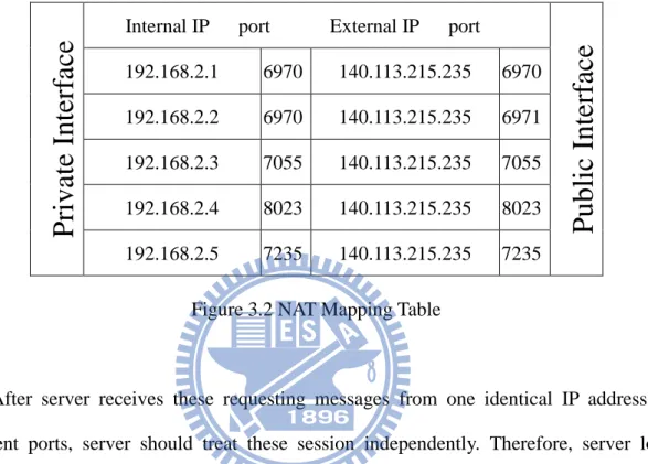
session transmission strategy. Since every clients are connecting to server through the NAT device. NAT maps these connections into one public IP address with different ports as in figure 3.2 shown.
Figure 3.2 NAT Mapping Table
After server receives these requesting messages from one identical IP address but different ports, server should treat these session independently. Therefore, server loads additional overhead to send video chunk to a LAN with many duplicated packets as Figure 3.3 shown.
Since the data payload of these packets are identical if those peers are watching the same IPTV channel. We suggested that server should build up a mechanism to detect this inconsequent case, and transmit only one copy of video data payload. In order to achieve this goal, server has to choose one of the peers behind same NAT to become superpeer and deliver the packet to it. The chosen peer should be responsible for deliver the packet to other peers in its LAN.
P
riva
te Int
erf
ace
Internal IP port External IP port
Public
Int
erf
ace
192.168.2.1 6970 140.113.215.235 6970 192.168.2.2 6970 140.113.215.235 6971 192.168.2.3 7055 140.113.215.235 7055 192.168.2.4 8023 140.113.215.235 8023 192.168.2.5 7235 140.113.215.235 723513
Internet
Streaming server
192.168.2.1 192.168.2.2 192.168.2.3 192.168.2.4 192.168.2.5 140.113.215.235 Fi Figure 3.3 Streaming server receives request from same LAN3.1 Peer joins
From the very beginning, clients send request to the streaming server as the program launches. For the signaling traffic, the reliability of connection is vital. Thus, TCP (Transmission Control Protocol) is suggested because of its retransmission and error detection mechanism. On the other hand, UDP (User Datagram Protocol) is mostly used for real-time applications when data loss can be compromised and compensated via using algorithms to compensate the data loss, which is adopted in this scheme. UDP sends the media stream as a series of small packets. This is simple and efficient; however, there is no mechanism within the user datagram protocol to guarantee delivery quality. It is up to the
14
receiving application to detect packet loss or packet corruption and to recover data via using error correction techniques. The streaming video may suffer a dropout while serials of data packets are lost due to network congestion. Therefore, we need to build up a mechanism that reports the QoS (Quality of Service) related data.
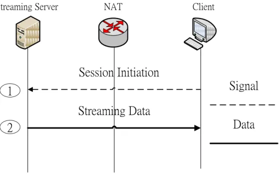
3.1.1 Single peer
First of all, a client launches the program and send session initiate message to the streaming server. After the server receives the request, it examines the entire online peer first; find out if there is a session already existed with same IP address but different ports, which means there are two or more clients behind same NAT. If the IP address of the request is not redundant, server will treat this session in traditional client-server method.
Step1. Client sends session initiate request to server.
Step2. Server respond client with video chunk in UDP packet, and set broadcast flag
equaled to 0 in the Pseudo Header.
Step3. Client buffers the payload (not including pseudo header) to be adequate for
15
1
Session Initiation
Streaming Data
Signal
Data
Streaming Server NAT Client
2
Figure 3.4 Single Client message flow
Since there are no other client requesting same channel in it's local area network, we have no alternative way to reduce neither inside nor outside traffic load. This situation cannot advantage the improvement of our proposed scheme.
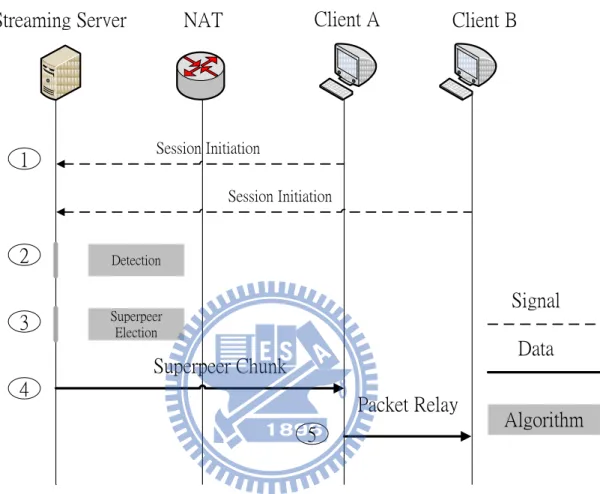
3.1.2 Multiple peers
While there are two or more clients requesting same IPTV channel. In traditional opinion, IPTV server would treat these connections as independent sessions. In other words, network traffic loads would be doubled while the number of user grows twice much as before. However, if some of the source IP address of these connections are identical, which means they are behind the same NAT and same LAN. We propose a scheme to reduce the
16
redundant data flow on the P2P under NAT network. Thus not only the network traffic load was reduced, but also both IPTV startup delay and switching delay were shortened.
Session Initiation Session Initiation Detection Superpeer Election
Superpeer Chunk
Packet Relay
Signal
Data
Algorithm
3
Streaming Server
NAT
Client A
Client B
4
2
1
5
Figure 3.5 Multiple Clients message flow
Step1. Client sends session initiate request to server.
Step2. Server examines all the current connections and detect that there are sessions that
have identical IP address same as the request.
Step3. Server chooses one of the peers that have identical IP address to become superpeer. Step4. Server responds each video chunk in UDP packet, and sets broadcast flag to 1 in
the pseudo header to the superpeer.
Step5. Superpeer receives the packet and resets the Broadcast Flag to 0, and then relays
17
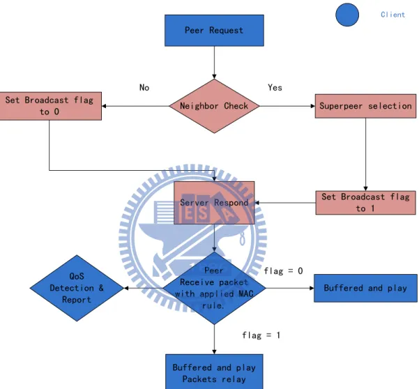
3.2 System Process
Peer Request
Neighbor Check Superpeer selection
Server Respond Set Broadcast flag
to 1 Set Broadcast flag
to 0
Yes No
Buffered and play flag = 0
Buffered and play Packets relay
Peer Receive packet with applied MAC
rule. flag = 1 Server Client QoS Detection & Report
Figure 3.6 System process flowcharts
Figure 3.6 illustrates the flow chart of the whole system. The blue part represents the Client side, and the red part stands for the Server side. First of all, Client starts the program and sends the request to the server, then waits for reply. After the server received the request and before it answered the client with streaming data, the server has to check whether if there are neighbors of this new coming client also watching the same channel.
18
After detecting, server setups a broadcast flag in pseudo header at the start of the application layer data, which actually is the streaming data payload. Flag 0 indicates that there are no other clients with same IP address connecting to server beforehand. Figure 3.7 shows the difference of these two types of pseudo header.
Pseudo_Header {Broadcast = 1 ;} … Payload Pseudo_Header {Broadcast = 0 ;} … Payload
Super peer Non-Super peer
Figure 3.7 Pseudo Header
In this case, server treats this case as traditional client-server architecture. On the other hand, flag is set to 1 to represent that the superpeer must receive this packet and then be responsible for relaying this packet to other ordinary peers in its local area network and behind the same NAT.
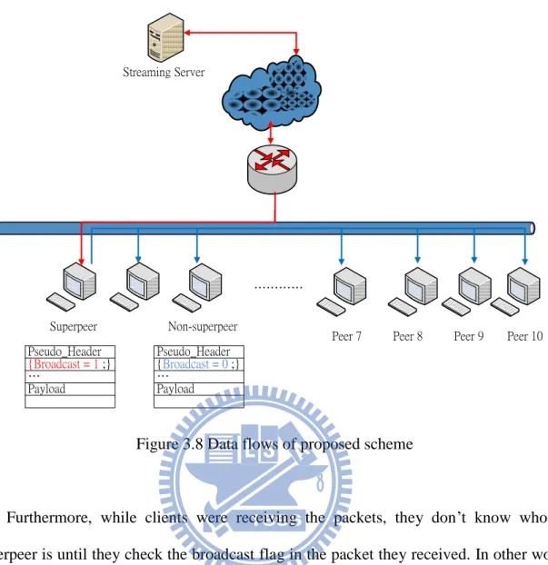
Therefore, after server has detected that there are two or more clients connecting with identical IP address. The server should have to pick one of these clients to become superpeer, who has the responsibility of relaying the packets. Figure 3.8 shows the state that more than two peers are connecting to the server and the receiving packets. The red connection indicates the direct connection between server and superpeer. The blues are the data flows among peers.
19 ………… Superpeer Non-superpeer Peer 9 Peer 8 Peer 7 Peer 10 Streaming Server Pseudo_Header {Broadcast = 1 ;} … Payload Pseudo_Header {Broadcast = 0 ;} … Payload
Figure 3.8 Data flows of proposed scheme
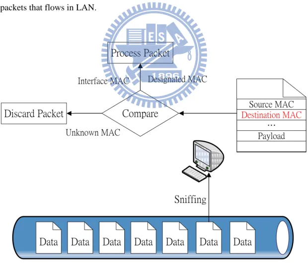
Furthermore, while clients were receiving the packets, they don’t know who the superpeer is until they check the broadcast flag in the packet they received. In other words, clients have to receive all the packets that flow on the LAN and inspect the broadcast flag inside the packet to decide relay the packet to other peers or not. In order to achieve this goal, network interface should be set to promiscuous mode, which is a configuration of a network card that makes the card pass all traffic it receives to the central processing unit rather than just frames addressed to it. Each frame includes the hardware (Media Access Control) address. When a network card receives a frame, it normally drops it unless the frame is addressed to that interface. In promiscuous mode, however, the card allows all frames through, thus allowing the computer to read frames intended for other machines or network devices. To remind, many operating systems require superuser privileges to enable promiscuous mode.
20
In this case, peers receive all the packets, even those that don’t belong to the console. Therefore, program has to check the MAC address in the packets it receives prior to processing the packets. However, peers don’t know who the superpeer is. For this reason, peer has to receive the MAC address that either addressed to its NIC or a unique one we assumed. The reason for we receive the MAC that addressed to NIC is the superpeer case. Since the connection between server and the superpeer is normal client-server architecture, superpeer should receive the packets that addressed to its MAC address. But for non-superpeer cases, peers receive packets that were forwarded from the superpeer. Consequently, non-superpeer receives those packets that are addressed to a unique MAC addressed that was configured in the program. Figure 3.9 shows the peer sniffing all the packets that flows in LAN.
Compare
Data
Data
Data
Data
Data
Data
Data
Sniffing
Source MAC Destination MAC … Payload Designated MAC Interface MAC Unknown MACProcess Packet
Discard Packet
21
To those non-superpeers, they only need buffer the streaming data payload in the packets they receive. On the other hand, superpeer should set the broadcast flag from 1 to 0, and modified the MAC address to the unique MAC address that we assumed before. After superpeer had done these modifications to the packets it receives, it sends the packets through the network sockets to the LAN it belongs to.
Furthermore, we might need a quality of service (QoS) monitoring mechanism in this system. We suggested that this control session may use TCP for QoS related messages. These messages include current download/upload speed, buffered packets size, packet loss rate, etc. With this QoS control mechanism, we can easily obtain session quality. For
example, if a peer reports that its packets loss rate is high, streaming server may reelects the superpeer. Thus, with these little control message, we can ensure the video broadcasting quality.
3.3 Peers Leaving
While the peers were trying to shut down the IPTV program or switch to another channel, it sends the message to inform server of this event. With this circumstance, it matters while the leaving peer is the superpeer. Since the superpeer is out of duty, the server should pick one peer of the rest peers in its LAN that are still watching this channel to become superpeer. The newly elected superpeer doesn’t know about the predecessor superpeer’s leaving until it receives the video chunk packet that was addressed the broadcast flag as 1. Additionally, the peer send leaving message to streaming server via control socket. Server decides to elect a new superpeer or remain the previous one.
22
Another situation is that there are only two peers in its LAN watching same channel. Certainly one of them is the superpeer, and the other one is the ordinary peer. After the superpeer leaving, only one peer stays in this LAN to watch this IPTV channel. Therefore, there is no need for the remaining peer to become superpeer.
3.4 Message Format
IPTV is a time-sensitive application and has the ability of tolerating slightly packets loss. Thus, the User Datagram Protocol is adopted in the proposed scheme. However, UDP uses a simple transmission model without implicit handshaking dialogues for providing reliability, ordering, or data integrity. UDP provides an unreliable service and datagram may arrive out of order, appear duplicated, or go missing without notice. UDP assumes that error checking and correction is either not necessary or performed in the application, avoiding the overhead of such processing at the network interface level.
However, slight packet loss is tolerable in streaming applications. Therefore, there is no necessary to build up retransmission mechanism in this proposed scheme. Thanks to the network congestion and traffic delay characteristic of network, the packets that peer receives may be out of order. Thus, sequence number is needed in this system. Firstly, server split the video into chunks, and forwards the packets to clients. The sequence number and the broadcast flag are set in the pseudo header.
Figure 3.10 shows the proposed message packet format. To begin with, we may fill the Ethernet Destination MAC either with unique MAC address or the peer’s network interface MAC address depends on whether the receiving peer is superpeer or ordinary peer in the
23
link layer header. Server transmits the video chunk to the superpeer with superpeer’s interface MAC address so that the packets can deliver to the superpeer successfully. For the relaying packets, superpeer modify MAC address field to the unique MAC and relay it.
In the IP header, since UDP is adopted in this system, the protocol field should be 17, which represented the User Datagram Protocol. Furthermore, while in the implantation phase, endianness issue was encountered. Endianness is the same as byte order. The usual contrast is whether the most-significant or least-significant byte is ordered first. A big-endian machine stores the most-significant byte first (at the lowest address), and a little-endian machine stores the least-significant byte first. Endianness not only determines the way we store and read the data, but also influences on the checksum calculation result.
24
Link Layer Header
0 5 6 11 12 14
Eth Destination MAC Eth Source MAC Eth Packet type
……
Internet Protocol Header
0 3 4 7 8 15 16 31
Version IHL Type of service Total Length
Identification Flags Fragment offset
Time to Live Protocol Header checksum
Source Address Destination Address
Options Padding
...
User Datagram Protocol Header
0 7 8 15 16 23 24 31
Source Port Destination Port
Length Checksum ……
Pseudo Header
0 1 2 31 Sequence Number flag25
Since the checksum was originally computed and filled by the network kernel. However, in the raw socket function, this field is authorized to the program itself, which means the kernel won’t compute it for us. Therefore, we need to rewrite the checksum function for both little endian and big endian cases and fill the checksum field.
IPv4, time to live (TTL) is an 8-bit field. In the Internet Protocol (IP) header, TTL is the 9th octet of 20. The time to live value can be thought of as an upper bound on the time that an IP datagram can exist in an Internet system. The TTL field is set by the sender of the datagram, and reduced by every host on the route to its destination. If the TTL field reaches zero before the datagram arrives at its destination, then the datagram is discarded and an ICMP error datagram (11 - Time Exceeded) is sent back to the sender. The purpose of the TTL field is to avoid a situation in which an undeliverable datagram keeps circulating on an Internet system.
However, under current network environment, personal computer may under several layers of routing devices to make the most use of IP address. Therefore, TTL should set to a small value in order to decrease the effect of network flooding as figure 3.11 shown.
26 IP Header TTL = 2 IP Header TTL = 1 IP Header TTL = 0 Internet
Figure 3.11 TTL subtracts while passing the network device
The sequence number is to ensure the packet ordering. While the server splits the video into video chunk packets, it assigns the Sequence Number to it with increasing order. Client buffers the video payload of packets by the ordering of Sequence Number to make sure that there are no video packets disordering for the playback.
At last, the broadcast flag in the Pseudo Header only has two different possible values. The flag is either 0 or 1 depending on the receiving peer target identity. The memory size of sequence number, we allocate as same as in TCP standard protocol – 32bits. However, in order to save the network bandwidth, packet size minimization is needed. Thus, the broadcast is set as a Boolean value, which occupies only one byte.
27
3.5 IPTV over Peer to Peer network
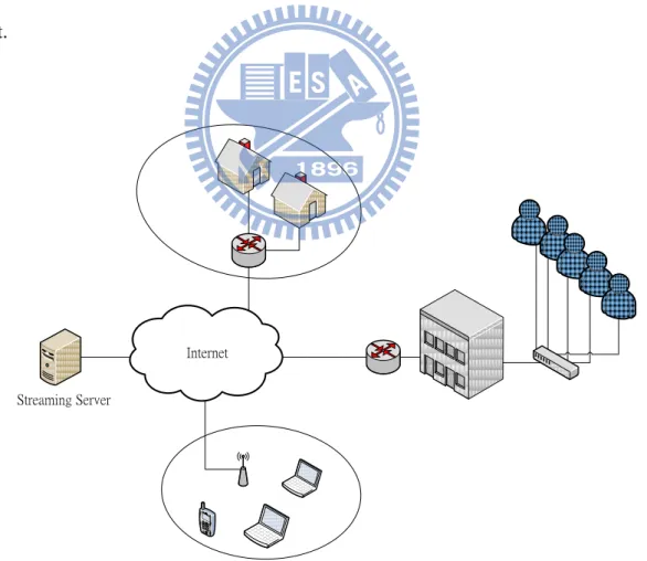
We can extend our proposed scheme to Peer to Peer IPTV architecture, which is a more popular and non-commercial business model. P2P IPTV, which means that a client not only receives the packet but also uploads the packets to other peers. The source of video chunk may either be server or other peers. Figure 3.12 shows the architecture of P2P IPTV.
Figure3.12 P2P-IPTV architecture
Since the source of the video chunk may either be the server or other peers in the p2p overlay, a tracker server is needed in this system. The tracker server responds client’s registration and informs client the IP address where it can obtain the video chunk. Figure3.13 shows the modified proposed scheme that applies to the peer to peer architecture.
28 ………….
Peer 1 Peer 2 Peer 3 Peer 7 Peer 8 Peer 9 Peer 10
Tracker Server Source Peer
Internet
Figure3.13 The proposed P2P-IPTV scheme
First of all, client send request to tracker server after the program launch or switches a channel. After tracker detect that there are several peers watching same channel from identical IP address, it assigns a source peer uploads the video chunk to the superpeer in the LAN. As we mentioned before, the broadcast flag is set to one and transmit to superpeer of the LAN. It means that the source peer is playing the role of streaming server in the scheme we proposed before. Additionally, the content provider, which may provides the content to the source peer.
In addition, tracker server assigns a single source to a LAN for simplicity. In the scheme we proposed, the increasing numbers of peers in a LAN that watches identical channel do not require more traffic load; it relies on the relaying of superpeer.
In reality, the download bandwidth and upload bandwidth are not symmetric. The upload bandwidth is often much smaller than download bandwidth. In traditional P2P IPTV architecture, upload bandwidth often be the bottleneck of the system. However, in our
29
proposed scheme, source peer transmit one copy of data packet despite the increasing number of peers. Thus, it allows one single source peer offer more peers’ sessions, which also solves the bottleneck issue. Tracker server is responsible for dispatch clients to a designated source peer in this scheme.
…………. Peer 1 Peer 2 Peer 3
Peer 9 Peer 8
Peer 7 Peer 10
Tracker Server Source Peer A Source Peer B
Channel B Channel A
LAN A
LAN B Internet
Figure3.14 Tracker server assigns source peer to other peers individually
Figure3.14 shows an example of the proposed P2P IPTV scheme. There are two different channels (A and B) and two LANs. Suppose several peers from LAN B logged in the program and are requesting for both channel A and B. Tracker server assigns source peer A for those requesting for channel A, and source peer B for channel B. If a new peer launched program and turn to channel A, tracker server assigns source peer A to the new peer. However, this new session doesn’t increase source peer A’s load, since the new peer receive the superpeer message of source peer A in LAN B.
30 Session Initiate Session Initiate Detection Superpeer Election
Source Peer respond
Packet Relay
Signal Data
Algorithm
Tracker Server AR Client A Client B
Source Peer respond Streaming Request
Streaming Request Video chunk
Source Peer
Superpeer Video chunk
Figure 3.15 Message flow of proposed P2P- IPTV scheme.
Figure 3.15 shows the signal flow of proposed P2P- IPTV scheme. Tracker server respond client with source peer information, which as the streaming server in IPTV architecture.
31
Chapter 4
Implementation and Experiment
We have implemented the proposed scheme on Linux kernel 9.04. The program is written in C. Thus, we justify our point of view. Furthermore, we analyze network bandwidth and performance improvement of IPTV.
4.1
Implementation
The proposed scheme needs two programs for IPTV architecture, server and the client programs. For P2P IPTV, server’s functionality is replaced by another peer that was designated by the tracker server. Thus, the client program plays both peer and streaming server roles.
Generally, the interface receives packets in three different types of MAC address, broadcast, multicast and the MAC address to it. Nevertheless, for the unique MAC we designated, we have to receive all the packets and drop the packets we don’t need. In order to achieve this goal, the interface should set to promiscuous mode in the first place. After that, promiscuous mode should be turned off while the program is closed.
In general socket programming, packet header including MAC layer, IP layer, and UDP header is filled by the network kernel. However, raw socket API allows us to modify the packet header by ourselves.
32 Control Socket Set Promiscuous Sniffing Packets QoS Detection Connect Server Connect Streaming
Buffer & Play Streaming Socket
Figure 4.1 Program function flowcharts
Figure 4.1 shows the client side programming model and function organization. In this framework, we can ensure the broadcasting quality and reduce network flow bandwidth.
To begin with, link layer, internet protocol layer and user datagram protocol are all predefined in Linux kernel, or we can build header of our own. However, there are small differences of header definition among various versions of Linux due to implementation issue. Therefore, system provided header format file is recommended.
General speaking, the operation system kernel computes the IP checksum automatically in normal socket function. Nevertheless, raw socket API offers us the authority of modifying network header field information, which means we have to compute the IP checksum value ourselves. There is also a checksum field in UDP header, but it can be omitted due to checksum is optional in UDP.
As we mentioned before, endianness is also an implementation issue, which also affect the way that checksum is computed. The increasing numeric significance with increasing memory addresses, known as little-endian, and decreasing numeric significance with increasing memory addresses (or increasing time), known as big-endian. Figure 4.2 shows memory allocation of these two different frameworks.
33
Figure 4.2 Memory allocation of big-endian and little-endian
The method used to compute the checksum is defined within RFC-1071. To compute the checksum, the checksum is set to 0 firstly. After that, all 16-bit words are summed together using one's complement. The sum is then one's complemented and this final value is inserted as the checksum field. Therefore, checksum value differs from these two different frameworks. For simplicity, two different checksum function is needed, one is for little endian and another one is for big endian. Beyond all questions, we have to detect present machine belongs to which endianness before calling the checksum function. To distinguish current machine belongs to which type of endianness, store a 4 bytes data, e.g.: “ABCD” as figure 4.2 shown, and read the first byte of this 4 byte data. If the data stores in the first byte is “A”, which means the current machine is big-endian machine and “B” stores in the first byte indicates little-endian machines similarly. After detecting the machine endianness, we can call the corresponding checksum functions for big-endianness and little-endianness. After fill in network header information and video chunk data in the application data the packet can be forwarded to clients.
34 Internet Data IP : 140.113.215.239 Port : 7200 MAC : 60:EB:69:13:5D:0B IP : 192.168.2.2 Port : 7300 MAC : 71:B3:0A:26:17:A9 IP : 114.32.219.123 IP : 192.168.2.3 Port : 7300 MAC : 0A:21:00:AC:15:0B Data Packet 1 Packet 2 Peer A Peer B Data
Figure 4.3 Network topology of implemented scheme
Figure 4.3 shows the implemented environment of the proposed IPTV scheme. Packet one sent from server to superpeer, and packet two sent from superpeer to ordinary peers. Figure 4.4 and 4.5 shows the content of these two packets respectively.
Since the packet sent from server to superpeer travels through internet. It should acts like a normal UDP streaming packet, which means the header fields of packet should be all correct. Otherwise, the packet will be dropped by other network devices (e.g. router).
35
Figure 4.4 Packet sent from server to superpeer
While packet passes through the NAT, it replaces the Destination address from public IP “114.32.219.123” to private IP “192.168.2.2” according to the NAT table. The Destination MAC is address to peer A and TTL should be large enough (default 64 in Linux kernel and 128 in Windows XP) to go through the network path. In addition, sequence number is incremental by one for every outgoing video chunk packets. Moreover,
Destination MAC 71:B3:0A:26:17:A9 Source MAC 60:EB:69:13:5D:0B Packet type Outgoing Version 4 IHL 5 Service 16 Total Length 20(IP)+8(UDP)+1024(APP) Identification : arbitrary Flag : D Fragments offset : 0 Time to Live : 64 Protocol : 17(UDP) Header checksum : Compute needed Source Address 140.113.215.239 Destination Address 192.168.2.2 Options : X Padding: X
Source Port : 7200 Destination Port : 7300
Length: 8(UDP)+1024 Checksum: Compute Needed
Sequence Number : 77
Broadcast Flag : 1 Data Payload…
36
broadcast flag set to one indicates that superpeer have to forward this packet to other peers after receiving this packet.
Figure 4.5 Packet sent from superpeer to ordinary peers
There are several differences between figure 4.4 and figure 4.5, “Destination MAC”, “Time to Live” and “broadcast flag”. Destination MAC is set to the unique MAC predefined in our program. “Time to live” is set to 3 in order to prevent failure routing and
Destination MAC 00:00:01:01:01:01 Source MAC 60:EB:69:13:5D:0B Packet type Outgoing Version 4 IHL 5 Service 16 Total Length 20(IP)+8(UDP)+1024(APP) Identification : arbitrary Flag : D Fragments offset : 0 Time to Live : 3 Protocol : 17(UDP) Header checksum : Compute needed Source Address 140.113.215.239 Destination Address 192.168.2.2 Options : X Padding: X
Source Port : 7200 Destination Port : 7300
Length: 8(UDP)+1024 Checksum: Compute Needed
Sequence Number : 77
Broadcast Flag : 0 Data Payload…
37
increase network burden. At last “broadcast flag” is set to zero to inform normal that there is no need to relay this packet.
4.2 Experiment setup and Numerical Analysis
4.2.1 Experiment Setup
To implement the scheme, we use a LINKSYS cable/DSL router with 4-port switch. We use a desktop be the streaming server and two laptop as peers connect to it. Figure 4.6 shows the experiment framework
1. Request
5. Relay
3. Request
2. Response
4. Detect
38
Compare to normal IPTV transmission scheme, streaming server has to forward video chunk to each clients. This task consumes a lot of network bandwidth. In this experiment, we compare normal IPTV transmission strategy and the scheme we proposed by measuring their processing capacity.
4.2.2 Bandwidth Analysis
First of all, we let the playing quality be 1000 kbps for streaming video and extra 10 to 15 percent traffic loads for quality of service and we assume that all the peers are under same LAN watching identical IPTV channel. To measure performance of proposed transmission scheme, we can estimate the bandwidth that passes through the NAT from server to LAN. As our expectation, network bandwidth grows linearly in traditional client-server transmission scheme while as shown in Figure 4.7
39
For the scheme we proposed, since the streaming data can be forwarded by superpeer. However, the QoS related packets are individual and time-sensitive that cannot be relayed by superpeer which is established in TCP connection. Thus, we keep every QoS connection alive and from peers to server directly. But for streaming packets, server chooses one of the peers to relay streaming packets. In other words, server sends only one copy of the streaming data, which may save lots of bandwidth.
As figure 4.8 shows, network bandwidth almost remains flat due to QoS data is light weight traffic compare to streaming data.
40
4.2.3 Startup delay Analysis
One of the measuring quantities in IPTV systems is the reduction of startup delays. While this problem does not exist in traditional television, in IPTV systems it is relevant, due to bandwidth limitation as well as the employment of buffers and overlay structures.
Generally, client buffers about 20 seconds of video frames before playback starts. In other words, the video of bit rates 512 kbps buffers 10 Mb before it starts to play. In this simulation, bit rate is 1024 kbps, and the total bandwidth of network is confined to 30Mb. While a peer joins the channel, it downloads and buffers the packets from server up to 20Mb at the highest speed the LAN offers, and then it starts to play. We describe the parameters for number analysis in Table 4.1.
Table 4.1 Parameters for analysis
Parameter Description
Bi Network bandwidth remains while peer i joins
Dstreaming Network traffic for Streaming data
DQoS Network traffic for QoS data
Mbuffer Buffer size for streaming data
T(startup,i) Startup delay time for peer i
For peer i request to streaming server, we have to calculate the remaining network bandwidth fist. The remaining bandwidth is expressed as Equation (1).
41
Bi. Therefore, startup delay time is calculated as Equation (2).
(1)
(2)
Figure 4.9 Startup delay of traditional IPTV framework
Figure 4.9 shows the experiment result. While the peer numbers more than 20, we can observe that the startup delay increases dramatically. The reason for this circumstance is that most of the network bandwidth (30 Mb) is occupied by previous sessions. Therefore, it takes more than 10 seconds to buffer for the last joined peer. If there are more peers connect to server in this LAN, it may suffer video LAG due to insufficient bandwidth for playing the video of bit rate 1024kbps.
42
bandwidth is not occupied by video traffic.
4.2.4 P2P-IPTV scale Analysis
One major difference between P2P-IPTV and IPTV is that IPTV has a strong streaming server that uploads heavy video traffic loads for clients. However, in P2P-IPTV, a peer obtains video chunk from other peers, which often limited by the small amount of upload bandwidth. Thus, a single peer cannot be connected for too many peers due to poor upload bandwidth limitation. In our proposed scheme, it may also improve the performance of P2P-IPTV.
43
Chapter 5
Conclusion and Future Work
In this thesis, we proposed a novel IPTV and P2P-IPTV transmission scheme under NAT architecture. In our proposed scheme, single transmission is used for streaming server instead of multiples. Therefore, lots of network bandwidth can saved in our proposed scheme in both IPTV and P2P-IPTV architecture without modifying any physical network devices, since all the works are done in software phase. We implemented the system to justify our proposed scheme. Furthermore, we analyze the network bandwidth we save in different video playing bit rates and startup delay compare with traditional IPTV/P2P-IPTV transmission scheme.
From our analysis, network bandwidth is saved significantly and startup delay, too. However, there are several questions need to be discussed and improved. Take superpeer election for example, the superpeer is responsible for forward streaming packets to other peers, which requires additional upload bandwidth. Thus, superpeer is considered with fine quality of network traffic. In addition, system may suffer broadcasting interruption due to superpeer offline. This is also an important issue for server to reelect a new superpeer and gives the authority of forwarding packets, which is so called “superpeer handover”. In this point of view, service interruption time minimization is our main focus.
The proposed scheme also faces problems that caused by NAT e.g. both side of source peer and superpeer are behind NAT. It causes connection establishment failure due to
44
restriction of NAT. To solve this problem, NAT traversal is required before the session initiation. However, the connection cannot be established when both sides are behind symmetric NAT. To conclude, there are several issues for how to construct an efficient P2P overlay of highly QoE (quality of user experience) P2P-IPTV but also saves network bandwidth.
45
References
[1] Diot, C. ; Levine, B.N. ; Lyles, B. ; Kassem, H. ; Balensiefen, D. ; Sprint Adv. Technol. Labs., USA “Deployment issues for the IP Multicast Service and Architecture” IEEE Network 2000 volume 14 p.78-88.
[2] Kim, K.I. ; Ha, J.L. ; Hyun, E.H. ; Kim, S.H. ; “Internet multicast provisioning issues for hierarchical architecture” Networks, 2001. Proceedings. Ninth IEEE International Conference 2001
[3] Castro, M. ; Druschel, P. ; Kermarrec, A.M. ; Rowstron, A.I.T. ; “Scribe: a large-scale and decentralized application-level multicast infrastructure” Selected Areas in
Communications, IEEE Journal Oct 2002
[4] Hei X.J. ; Yong, L. ; Ross, K.W. ; “IPTV over P2P Streaming Networks the Mesh-Pull
Approach” IEEE Communication Magazine Volume 2008 46 p. 86-92
[5] Huang, N.F. ; Chu, Y.M. ; Chen, Y.R. ; “Design of a P2P Live Multimedia Streaming
System with Hybrid Push and Pull Mechanisms” Communications and Mobile
Computing (CMC), 2010 International Conference 2010 p.541-545
[6] Tang, Y. ; Luo, J.G. ; Zhang, M. ; Yang S.Q. ; Zhang, Q. ; “Deploying P2P Networks for Large-Scale Live Video-Streaming Service”. IEEE Communication Magazine 2007 volume 45 p. 100-106
[7] Hei, X. ; Liang, C. ; Liang, J. ; Liu, Y. ; Ross, K.W. ; “A Measurement Study of a
Large-Scale P2P IPTV System " IEEE Transaction Multimedia 2007 volume 9 p. 1672-1687
[8] Silverston, T. ; Fourmaux, O. ; “Measuring P2P IPTV Systems” ACM Network & Operating Systems Support for Digital Audio & Video (ACM NOSSDAV), 2007. [9] Yang, X. ; Du, X.J. ; Zhang, J.Y. ; Hu, F. ; Guizani, S. ; “Internet Protocol Television
(IPTV): The Killer Application for the Next-Generation Internet” Communications Magazine, IEEE 2007
[10] Lu, M.T. ; Wu, J.C. ; Peng, K.J. ; Huang, P. ; Yao, J.J. ; Chen, H.H. ; “Design and Evaluation of a P2P IPTV System for Heterogeneous Networks” Multimedia, IEEE Transactions 2007
[11] Xie, S.S. ; Bo, L. ; Keung, G.Y. ; Zhang, X.Y. ; “Coolstreaming: Design, Theory, and Practice” Multimedia, IEEE Transactions 2007