行政院國家科學委員會專題研究計畫 成果報告
奈米壓印製程機械與熱變形之數值研究與製程參數最佳化
研究成果報告(精簡版)
計 畫 類 別 : 個別型 計 畫 編 號 : NSC 99-2218-E-151-005- 執 行 期 間 : 99 年 08 月 01 日至 100 年 10 月 31 日 執 行 單 位 : 國立高雄應用科技大學模具工程系 計 畫 主 持 人 : 林香君 報 告 附 件 : 出席國際會議研究心得報告及發表論文 公 開 資 訊 : 本計畫可公開查詢中 華 民 國 100 年 10 月 31 日
中文摘要: 本研究應用有限元素模擬技術決定奈米壓印最佳製程參數。依 據數值模擬結果,基板外形與成型材料 PMMA 初始厚度可為影 響壓印力因子。研究證明採用 PMMA 初始厚度為模穴深度三 倍,基板與模穴幾何 AR 值愈接近,能有效降低壓印力需求,進 而減少圖案機械變形。考量製程條件缺陷可為影響圖案變形因 子,本研究針對不均勻壓印力與基板平坦度亦進行探討。在維 持線寬尺寸下,降低模穴 AR 值可有效減少圖案因操作壓印力 對壓降補償而產生機械變形。基板表面擾度遠低於成形材料厚 度時,對典型 NIL 影響將可忽略。
英文摘要: Nanoimprint lithography is analyzed by FEM approach to determine the optimal NIL system for minimizing imprint pressure applied in pressing step. Under conventional process conditions, imprint pressure is investigated based on substrate topology and various initial thickness of polymer. This study demonstrates that the
imprint pressure can be effectively reduced as the substrate design is compatible with the groove; the substrate shaped matching the groove feature. An initial thickness of polymer can be a parameter to decrease the imprint pressure. Incorporating with the polymer thickness equal to three times as much as the height of pattern and applying the described substrate design yield the mechanical distortion to be minimized. Imprint pressure associated with ill process conditions including non-uniform loading distribution and non-flat substrate are studied in this work as well. For NIL suffering from non-uniform process loading, decreasing aspect ratio of pattern eliminates the mechanical distortions resulting from loading
compensation for the pressure drop. The effect of substrate fluctuation on the imprint pressure can be negligible as it is very small compared with the polymer thickness.
行政院國家科學委員會補助專題研究計畫
▓ 成 果 報 告
□期中進度報告
計畫名稱:
(奈米壓印製程機械與熱變形之數值研究與製程參數最佳化)
計畫類別:▓個別型計畫 □整合型計畫
計畫編號:NSC - - - -
-
執行期間: 99 年 8 月 1 日至 100 年 7 月 31 日
執行機構及系所:國立高雄應用科技大學 模具工程系
計畫主持人:林香君
共同主持人:
計畫參與人員:陳冠宏,陳彥瑋
成果報告類型(依經費核定清單規定繳交):▓精簡報告 □完整報告
本計畫除繳交成果報告外,另須繳交以下出國心得報告:
□赴國外出差或研習心得報告
□赴大陸地區出差或研習心得報告
▓出席國際學術會議心得報告
□國際合作研究計畫國外研究報告
處理方式:
除列管計畫及下列情形者外,得立即公開查詢
□涉及專利或其他智慧財產權,□一年□二年後可公開查詢
Introduction
NIL [1] is a novel fabrication technology that straightly applies mechanical compression to produce nano-scaled components. Its advantages of low cost, high throughput and high resolution render NIL become one of the main approaches for fabricating fine-dimensional structures. While NIL is simple and excludes complex processes and thereby attracts worldwide attention in lately years, the structural distortion, potentially resulting in the nano-devices malfunctioned, is often the challenge for this technique. Consequently, reducing the pattern distortions is so crucial for NIL.
The pattern mechanical distortion can be significantly affected by imprint pressure that is associated with not only process parameters, for instance imprint temperature [2-3], but the design for NIL system including a mold, a substrate and the polymer initial thickness. According to mechanics aspect, the required imprint compressions applying on the resist polymer materials are equivalent for modes having the same pattern features. Therefore, in order to effectively decrease the imprint pressure and subsequently reduce the mechanical distortion induced in the pattern, this study concentrates on analyzing the effect of designs for substrate and initial thickness of polymer on the process loading and summarizes the optimal design rule for NIL system.
In practical manufactures like NIL, the uniformity of process loading throughout the area of interest is often difficult to be retained. Under non-uniform imprint pressure, the groove created in a mold can be incompletely filled in the pressing process, and thus can make pattern defects occurred. This study investigates the polymer deformation process in the groove under such the ill loading condition to understand the influence of non-uniform imprint pressure for NIL. The non-uniform loading analyzed here is modeled as the imprint compression drops linearly throughout the mold. Based on the numerical analysis, an optimal groove design is determined and demonstrated its validity for the elimination of mechanical distortion resulting from such loading imperfection. Non-flat substrate regarded to as an ill process condition in this work is also analyzed to investigate its effect on the imprint pressure.
Numerical Analysis
Nanoimprint lithography uses thermoplastic polymer as the resist to form the desired patterns. Prior to pressing, the resist is heated above its glass transition temperature, which yields the material become rubber elastic [4]. Different from an elastomer, the rubber elastic body is incompressible and allows large deformation.
A theoretical model developed by Mooney and Rivlin [5-6] is able to precisely analyze the large elastic deformation for incompressible materials and whose potential function is expressed as the follows.
(
)
(
)
10 1 3 01 2 3 W =C I − +C I − , 2 2 2 1 1 2 3 I =λ +λ +λ (1) 2 2 2 2 2 2 2 1 2 2 3 3 1 I =λ λ +λ λ +λ λWhere W is strain energy density function, C and 10 C are material constants, 01 λi is the th
i principal
strain and I and 1 I are the first and second strain invariants, respectively. Assuming that the polymer 2
deformation process based on Mooney-Rivlin theory, using FEM ANSYS.
I. Numerical analysis under conventional process conditions
NIL fabrication technology is acknowledged as a promising approach to produce nano-scaled structure. While this technique is simple and less elaborative in process, it always suffers the challenge of distortion which specifically needs to be minimized for the fine-dimensional components. Mechanical distortion can be significantly affected by imprint pressure, therefore many works had investigated the relations among the imprint loading, process temperature as well as pattern aspect and duty ratios to determine the optimal process conditions. Unlike the previous studies concentrating on the operation conditions and pattern geometry, the present work emphasizes on optimizing the NIL system by analyzing the substrate topology and polymer initial thickness to effectively reduce the mechanical distortion in pressing process.
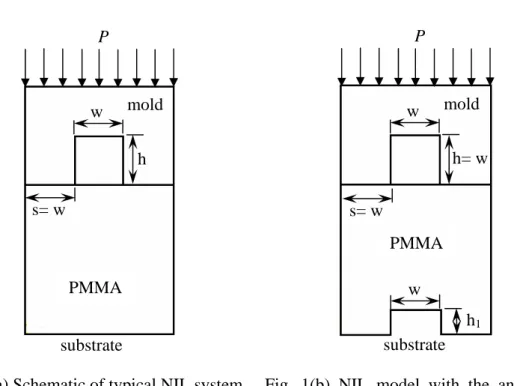
Figures 1 show the schematics of NIL analytical models. The pattern studied here is prismatic shaped with dimensions of 50 nm wide and 50 nm high. The resist PMMA assumed to be heated about 180°C has an initial thickness equal to three times as much as the pattern height. In FEM analysis, the contact boundary is assigned to simulate the polymer deformation process in the groove and the substrate is completely constrained. Along the top edge of a mold, a uniform compression is applied as obtained in Figs. 1.
A conventional NIL system is designed consisting of a substrate with a flat surface as shown in Fig. 1(a). Based on this design, the mechanical deformation of polymer strongly relies on the imprint loading in the pressing step. In this study, the substrate is shaped to compromise the groove as can be seen in Fig. 1(b). By implanting the pattern feature with even the smaller aspect ratio on the substrate, it helps the polymer readily flow into the groove through the pseudo tunnel which is gradually formed between the mold and substrate as the resist is compressed. Therefore, the process loading needed in pressing is reduced and that results in the decrease of pattern mechanical distortion in NIL fabrication.
II. Numerical analysis based on ill process conditions A. Non-uniform imprint loading
NIL analysis in previous studies typically assumes that the imprint pressure distributes uniformly throughout the area of interest. However, in practical manufactures, the uniform process loading is often difficult to be remained. The imperfection of loading condition can potentially induce the pattern defect in alternative degrees which is specifically required to be vanished for NIL. Therefore, it is crucial to investigate the influence of non-uniform imprint pressure on polymer deformation in the groove and also determine an optimal manner to minimize the impact for such ill process loading condition.
Figure 2 shows the distribution of non-uniform imprint loading acting on the top edge of a mold. The ill loading condition analyzed here considers pressure drop linearly from the center to the edge of a mold, as expressed in Fig. 2. Due to the pressure drop, the groove can be incompletely filled as the process loading is less than the required compression, the minimal imprint pressure to fill up the grooves. Although applying the loading compensation helps decreasing the risk of unfilled grooves occurred, it can increase the mechanical distortion. Therefore, instead of considering the loading compensation for the pressure drop, the present work optimizes the groove design to reduce the effect of non-uniform loading on the pattern formation.
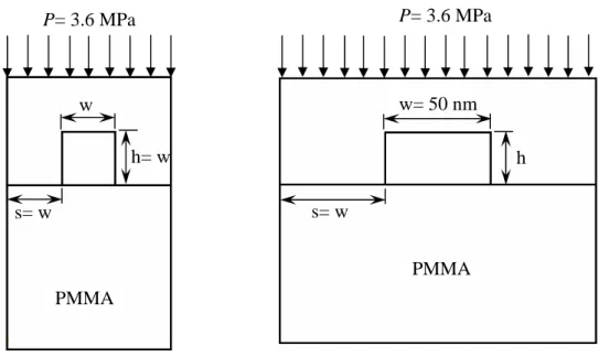
Figure 3(a) shows an NIL analytical model used to investigate the relationship between imprint pressure and pattern width. Fixed the pattern aspect and duty ratios as the same as those obtained in Fig. 1(a), the imprint pressure is calculated for the pattern width w varying from 6.25 nm to 50 nm. The pattern aspect ratio (AR) related to imprint loading is also studied here as shown in Fig. 3(b). Modeling results of Figs. 3
will give sufficient information to determine the groove parameter that intensively affects the process loading, and that is applied to optimize the groove design under ill loading condition.
B. Non-flat substrate
Minimizing pattern distortion is very crucial for NIL approach. Due to the pattern mechanical distortion strongly affected by imprint pressure, it is informative to study fabrication parameters that may influence the process loading. Motive from recognizing that the planarization of substrate is necessary but difficult to be attained, the authors consider fluctuations on the substrate as obtained in Fig. 4 in the present NIL analysis. The non-flat substrate modeled here assumes the fluctuations h2= 0.2h periodically distributing
on the surface as shown in Fig. 4, from which the corresponding evaluated imprint pressure is desired to help understand the effect of non-flat substrate on the process loading.
Numerical Results
I. Conventional process conditionsThis study attempts to effectively reduce the imprint pressure needed for NIL process by compromising the substrate geometry to the groove feature. In order to substantiate the validity of the present manner, a conventional NIL system containing a typical substrate feature as obtained in Fig. 1(a) is also analyzed in this work. The present analysis assumes that the NIL system applying PMMA as the resist is heated up to 180°C and uniformly compressed with a value of 3.6 MPa on the top edge of a silicon-based mold. On the bottom of the NIL system, a full constrain is assigned along the substrate. Based on such analytical conditions, the corresponding mechanical deformation of pattern induced in the conventional NIL system is evaluated as shown in Fig. 5(a) which indicates the filling rate is approximately 0.72. Attaining the filling rate at 0.72, Fig. 5(b) shows the imprint pressure determined by varying the substrate feature of Fig. 1(b) from h1/h = 0.5 to h1/h = 1.5, where h1 is the height of pseudo pattern feature implanting on the substrate
and h is the pattern height. In Fig. 5(b), it illustrates the conventional substrate feature resulting in the maximal imprint loading needed for NIL fabrication, comparing with that for those substrates shaped compromising the groove design. Moreover, the imprint pressure can be decreased as h1 increases. For h1
equal to the height of pattern, a drastic decrease in process loading is attained as shown in Fig. 5(b) and that indicates h1 = h is the optimal parameter for NIL substrate design.
Previously, NIL works had demonstrated the initial thickness of polymer can be a parameter to influence the imprint pressure; therefore this study analyzes the effect of polymer thickness to provide the best design rule for NIL system. Figure 5(c) shows the relationship between the imprint pressure and the initial thickness of polymer based on the described optimal substrate feature as shown in Fig. 1(b) applying h1/h=1.
As can be seen in Fig. 5(c), PMMA thickness is almost independent of imprint pressure as it varies between 2.5h and 4h. Insufficient polymer can result in the groove incompletely filled; on the contrary, it can be elaborative for the post-process and increase cost as well. Furthermore, due to involving the pattern feature designed on the substrate as obtained in Fig. 1(b), an optimal initial thickness of polymer can be employed about 3h for NIL system.
II. Ill process conditions
(a) Non-uniform imprint pressure
The uniformity of imprint pressure throughout the process area of interest is required for NIL to reduce the pattern defects occurred in pressing step. However, in real manufacturing process it is difficult to maintain
such loading requirement which frequently fails due to the pressure drop. In this study, an imprint loading with pressure drop throughout is referred to as an ill loading condition and analyzed its effect on the pattern mechanical deformation in the groove. An optimal NIL system is also determined based on such ill loading condition.
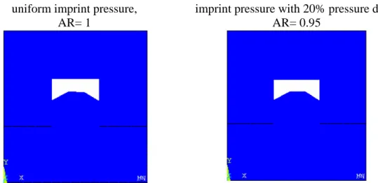
In this work, the NIL system contains a groove with dimensions of 50 nm width and 50 nm height and is loaded by non-uniform compression linearly varying from 3.6 MPa at the center of the mold to 2.88 MPa at the end as indicated in Fig. 2. The 20% decrease in imprint pressure throughout mechanically changes PMMA deformation mechanism and results in the filling rate decreases comparing with that under uniform loading, as obtained in Figs. 6(a). Therefore, in order to compensate the effect of non-uniform loading, reducing the imprint pressure needed is necessitated for NIL. Figure 6(b) indicates the relationship between the imprint pressure and the pattern width based on the fixed aspect ratio at 1 and it demonstrates the variation of pattern width can be independent of the imprint pressure. Contrast with the analysis in Fig. 6(b), fixed the pattern width Fig. 6(c) illustrates the imprint compression decreases as the pattern aspect ratio decreases. Therefore, decreasing the aspect ratio for the groove can be an optimal design rule for NIL under the non-uniform imprint loading condition. Figures 6(d) shows the comparison of PMMA deformations for the pattern aspect ratio at 1 and 0.95 under the uniform imprint pressure of 3.6 MPa and non-uniform loading as described, respectively. The result of Figs. 6(d) substantiates the validity of the described design rule for the ill process loading condition.
(b) Non-flat substrate
Although the authors are aware that the initial thickness of polymer can advantageously reduce the effect of non-flat substrate on pattern deformation process, it is still informative to understand the degree of influence for the substrate fluctuation on NIL. Figure 7 shows PMMA deformation in the pressing step based on NIL employing the conventional and described substrate in Fig. 4. As can be seen in Fig. 7, the mechanical behaviors of PMMA resulting from those two types of substrates are approximately same and that gives the effect of non-flat substrate can be omitted for NIL fabrication even the fluctuation is approaching to 0.2h.
Summary
Optimizing the system design and process conditions is very crucial for NIL to minimize the pattern distortion occurred during the fabrication procedures. The present study emphasizes on providing design rule for NIL system to reduce the imprint pressure needed in pressing step and decreases the effect resulting from ill process conditions including non-uniform loading and non-flat substrate. By compromising the substrate feature with the groove design, the imprint pressure can be effectively reduced. For NIL confronting the non-uniform imprint compression, the aspect ratio of groove should be reduced to compensate the effect of loading drop in the process area. The effect of non-flat substrate on polymer deformation obtains small enough to be neglected due to the polymer thickness employed in NIL much greater than the degree of substrate fluctuation.
Acknowledgements
Greatly appreciate NSC of Taiwan for providing funds (Grant#99-2218-E-151-005) to support this work.
Reference
[1] Chou, S.Y., Krauss, P.R., Renstrom, P.J., Applied Physics Letter, 67, 3114 (1995)
[2] Hirai, Yoshihiko, Konishi, Takaaki, Yoshikawa, Takashi and Yoshida, Satoshi, The Journal Vacuum Science and Technology, B 22(6), Nov/Dec (2004)
[3] Stoyanov, Stoyan, Amalou, Fraid, Sinclair, Keith, Bailey, Chris, Desmulliez, Marc P.Y., the 9th International Conference on Thermal, Mechanical and Multiphysics Simulation and Experiments in Micro-Electronics and Micro-System, 1-8, EuroSimE (2008)
[4] Sperling, L.H., Introduction to Physical Polymer Science, Wiley-Interscience, New York, (2001) [5] Mooney, M., Journal of Applied Physics, Vol. 11, pp. 582 (1940)
[6] Rivlin, R. S., Philosophical Transactions of the Royal Society of London, Series A, 241, pp. 379-397 (1948)
6
Fig. 1(a) Schematic of typical NIL system Fig. 1(b) NIL model with the analytical substrate feature
Fig. 2 NIL system subjected to non-uniform imprint pressure PMMA mold h w P substrate s= w PMMA mold h= w w P substrate h1 s= w w PMMA h= w w= 50 nm P= 3.6 MPa s= w 0.8P 0.8P
7
Fig. 3(a) NIL model analyzing the effect of pattern width
Fig. 3(b) NIL model analyzing the aspect ratio
Fig. 4 Schematic of non-flat substrate PMMA h= w w P= 3.6 MPa s= w PMMA h w= 50 nm P= 3.6 MPa s= w h= w w= 50 nm P= 3.6 MPa h2= 0.2h s= w
8 0 1 2 3 4 5 6 0 0.5 1 1.5 h1/h imp rin t p res su re ( M P a )
Fig. 5(a) PMMA deformation under NIL compression of 3.6 MPa
Fig. 5(b) Imprint pressure related to the
conventional and described substrates as obtained in Figs. 1 0 1 2 3 4 5 6 2.5 3 3.5 4 thickness/h im p rin t p re ss u re (M P a)
9
Loaded by uniform imprint pressure Loaded by imprint pressure with 20% pressure drop
Figs. 6(a) PMMA deformation resulting from uniform and non-uniform imprint pressures
0.0 2.0 4.0 6.0 8.0 10.0 0 10 20 30 40 50 60 pattern width (nm) im p rin t p re ss u re ( M P a ) 0.0 2.0 4.0 6.0 8.0 10.0 0 0.5 1 1.5 2 pattern AR(=h/w) im p ri n t p re ss u re (M P a )
Fig. 6(b) Imprint pressure related to pattern width
Fig. 6(c) Imprint pressure related to pattern aspect ratio
10
uniform imprint pressure, AR= 1
imprint pressure with 20% pressure drop, AR= 0.95
Figs. 6(d) PMMA deformation based on pattern aspect ratios of 1 and 0.95, under uniform and non-uniform imprint compression, respectively
國科會補助專題研究計畫項下出席國際學術會議心得報告
日期:100 年 10 月 27 日一、參加會議經過
ASME McMAT 為一跨足機械各領域之研討會,因此於為期三天研討會中,本人除了在計
算奈米技術小組座談會中發表個人於模擬 NIL 製程之研究成果外,亦參與高分子奈米
複合材料,生物組織力學等座談會,受益頗多。
二、與會心得
藉由參與 McMAT 研討會不僅增加本人與國外學者學術交流機會,同時也於三天研討會
中,接觸到非本專業領域之研究,對於本人無論在未來研究工作或提升國際學術界能
見度上均有實質幫助。
三、考察參觀活動(無是項活動者略)
略。
四、建議
計畫編號
NSC 99-2218-E-151 -005
計畫名稱
奈米壓印製程機械與熱變形之數值研究與製程參數最佳化
出國人員
姓名
林香君
服務機構
及職稱
國立高雄應用科技大學 模具系
助理教授
會議時間
100 年 5 月 30 日
至
100 年 6 月 1 日
會議地點
Chicago
會議名稱
ASME 2011 Applied Mechanics and Materials Conference(McMAT)發表論文
無。
五、攜回資料名稱及內容
研討會目錄與光碟一片。
六、其他
McMat2011-4155 Technical Presentation
Numerically Optimize NIL Fabrication based on Well and Ill Process Conditions
Authors
Shiang-Jiun Lin, National Kaohsiung University of Applied Sciences Han-Lin Chang, National Kaohsiung University of Applied Sciences
Abstract
Hot-embossing nanoimprint lithography is studied by FEM approach to analyze pattern mechanical distortions under well and ill process conditions. Neglecting process imperfections, pattern distortion is minimal if the operation parameters, polymer initial thickness as well as the pattern aspect and duty ratios are optimized. As it is often difficult to maintain the uniformities of loadings and process platform throughout the fabrication area, non-uniform imprint pressure and non-flat
substrate are considered as ill process conditions to investigate their effects on the pattern mechanical deformation behavior. Numerical results indicate that the pattern distortion is strongly dependent on the degree of non-uniformity of imprint pressure. The more imprint pressure distributes non-uniformly, the more
mechanical distortion can be induced due to the loading compensation for the pressure drop. The optimization for NIL system based on ill process conditions is studied as well in this work.
國科會補助計畫衍生研發成果推廣資料表
日期:2011/10/27國科會補助計畫
計畫名稱: 奈米壓印製程機械與熱變形之數值研究與製程參數最佳化 計畫主持人: 林香君 計畫編號: 99-2218-E-151-005- 學門領域: 應力應變與成型無研發成果推廣資料
99 年度專題研究計畫研究成果彙整表
計畫主持人:林香君 計畫編號: 99-2218-E-151-005-計畫名稱:奈米壓印製程機械與熱變形之數值研究與製程參數最佳化 量化 成果項目 實際已達成 數(被接受 或已發表) 預期總達成 數(含實際已 達成數) 本計畫實 際貢獻百 分比 單位 備 註 ( 質 化 說 明:如 數 個 計 畫 共 同 成 果、成 果 列 為 該 期 刊 之 封 面 故 事 ... 等) 期刊論文 0 0 100% 研究報告/技術報告 0 0 100% 研討會論文 0 0 100% 篇 論文著作 專書 0 0 100% 申請中件數 0 0 100% 專利 已獲得件數 0 0 100% 件 件數 0 0 100% 件 技術移轉 權利金 0 0 100% 千元 碩士生 2 2 100% 博士生 0 0 100% 博士後研究員 0 0 100% 國內 參與計畫人力 (本國籍) 專任助理 0 0 100% 人次 期刊論文 0 1 100% 研究報告/技術報告 0 0 100% 研討會論文 1 1 100% 篇 論文著作 專書 0 0 100% 章/本 申請中件數 0 0 100% 專利 已獲得件數 0 0 100% 件 件數 0 0 100% 件 技術移轉 權利金 0 0 100% 千元 碩士生 0 0 100% 博士生 0 0 100% 博士後研究員 0 0 100% 國外 參與計畫人力 (外國籍) 專任助理 0 0 100% 人次其他成果