as soon as data is available. Thus, the intermediate data storage is reduced to only the four 4 4 blocks instead of whole 16 16 macroblock. The resulting design can achieve 100 MHz with only 13.41K gate count and support real-time deblocking operation of 2K 1K@30 Hz video application when clocked at 73.73 MHz by using 0.25- m CMOS technology.
Index Terms—Deblocking filter, H.264/AVC, VLSI architecture design.
I. INTRODUCTION
T
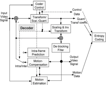
HE BLOCK-based video coding, due to its simple and regular block structure, has been widely used in various video coding standards, such as MPEG-1, MPEG-2, MPEG-4, and H.26x. However, the block structure also introduces the blocking effect [1], [2], which becomes worse especially in the low bit rate or highly compressed video environment. To reduce the artifact, the deblocking filter is adopted to improve both ob-jective and subob-jective video quality, either inside or outside the coding loop. The in-loop approach adopted by the H.264/AVC standard [3], as shown in Fig. 1, improves the quality of refer-ence frame, thereby improving the perceived quality of the de-coded video.However, the deblocking filter in H.264/AVC is both compu-tational and memory intensive due to its highly adaptive mode decision and small 4 4 block size [4]. The adaptive mode de-cision is required for each edge to distinguish real edges from block artifacts. The small 4 4 block size used in H.264/AVC requires almost every pixel in a frame loaded from and written to frame memory for deblocking operations. It is reported that even with highly optimized filtering algorithm, the deblocking oper-ation still occupies one third of the computoper-ational complexity of a decoder [4]. Thus, VLSI implementation is necessary for high-performance or low-power applications such as HDTV or mobile phone.
For an efficient VLSI design of the deblocking filter, the memory bandwidth and intermediate buffer are the major design issues. In the H.264/AVC standard, the adaptive de-blocking filter is applied on edges of each 4 4 block in a
Manuscript received November 23, 2004; revised June 7, 2005 and November 3, 2005. This work was supported by the National Science Council, Taiwan, R.O.C., under Grant NSC-93-2200-E-009-028. This paper was recommended by Associate Editor T. S. Rosing.
The authors are with the Department of Electronics Engineering, National Chiao Tung University, Hsinchu, Taiwan 300, R.O.C.
Digital Object Identifier 10.1109/TCSII.2006.875323
Fig. 1. Encoding loop of H.264.
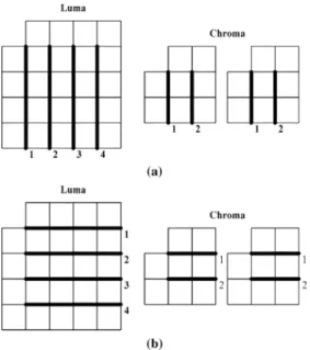
macroblock (MB). For details, readers may refer to [3]. The processing order of the deblocking filter in an MB, shown in Fig. 2, first processes the four vertical edges and transposes the intermediate data, and then processes the four horizontal edges. The major drawback of this direct approach is that intermediate data storage is as large as a whole 16 16 MB size. Besides, this data flow accesses the 4 4 block four times for original and intermediate data, which results in high bandwidth. Previous approaches directly adopted this coding flow as in the reference software [5], and thus required a large buffer size and high bandwidth [6].
Instead of the direct approach, this brief proposes an in-place computing architecture that reuses intermediate data as soon as data is available. With such full data reuse, both memory band-width and intermediate storage can be reduced. The resulting design can easily meet the real-time high resolution require-ment (2048 1024@30 Hz) with low-cost hardware such as live broadcasting or HDTV applications.
The organization of this brief is as follows. In Section II, we describe the full data reuse computational flow of deblocking filter in H.264/AVC. In Section III, we present the hardware architecture. Then, the architecture performance will be com-pared with other approaches in Section IV. Finally, concluding remarks are made in Section V.
II. FULLDATAREUSECOMPUTATIONALFLOW Fig. 3 shows the 4 4 block index for the full data reuse computational flow. Before deblocking processing, the blocks above (Blocks 1–4) and left (Blocks 5, 10, 15, and 20) from the 1057-7130/$20.00 © 2006 IEEE
Fig. 2. Processing orders of vertical edges and horizontal edges in a MB. Each block is a 42 4 pixels block. (a) Horizontal filtering over vertical edges. (b) Vertical filtering over horizontal edges.
Fig. 3. 42 4 block index of the full data reuse flow.
current MB are first retrieved from external memory for current MB deblocking. In Fig. 3, data from Blocks 1–4, 5, 10, 15, and 20 have been vertically and horizontally filtered as part of the filtering process for the above and left MBs, respectively. For simplicity, we will denote the block number as blk i, where i is from 1 to 24. These block data will be combined with current MB data to complete the deblocking operations.
Fig. 4 shows the full data reuse computational flow that main-tains the same result as specified by the H.264/AVC standard. The processing order is as denoted by the number in Fig. 4. As shown in Fig. 4(a), we process edges of each 4 4 block from the left-top-most block (blk6), and proceed to the right-bottom-most block (blk24). Start from the left-top-right-bottom-most 4 4 block (blk6). We first do the horizontal filtering over its two vertical edges, (edge 0 and edge 1). Then, since all data is available for horizontal edge 2 (intermediate data from blk1 and blk6), we can do the vertical filtering over the top horizontal edge (edge 2). This horizontal-vertical interleaved approach is repeated for each 4 4 block in a raster scan order, as the edge number shown in Fig. 4(a) and (b).
With the interleaved approach, the intermediate data will be used immediately. Thus, we can save the memory access and buffer required to process the left, top, and right edge in a 4 4 block. The only buffer and memory access remaining are the intermediate data for the bottom edge in a 4 4 block that will be used in the below MB. Therefore, we need only four 4 4 blocks bits above the current filtering block row (e.g., store blk6-blk9 when processing blk11–blk14), rather
Fig. 4. Processing edge order of boundaries for (a) luma data, and (b) chroma data.
Fig. 5. Overall architecture.
than a whole MB bits as in the conventional data flow. Because of this high data reuse, internal memory access number and size are both greatly reduced. Note that the de-blocking algorithm, as described in the brief, in general, requires all MB data to be received prior to application of the deblocking filter process for flexible MB ordering (FMO) and arbitrary slice order (ASO) cases in H.264. The in-place algorithm is compat-ible to MB adaptive frame field (MBAFF) feature of H.264/AVC since our algorithm only changes the computing order inside the MB and keeps the MB processing order unchanged.
The in-place deblocking algorithm is also applicable to software implementations due to low memory requirement and in-place computation. For example, a software implemen-tation might, depending on the computing platform, be able to load all data necessary to filter a 4 4 block into on-chip registers, thereby providing extremely fast computation of the filter process. The described technique might be particularly powerful if the deblocking filter process is carefully pipelined (e.g., prefetch/DMA picture data from memory to L1 cache followed by a process designed to move data from L1 cache to on-chip registers).
III. IN-PLACECOMPUTINGARCHITECTURE
A. Overall Architecture and Computation Flow
Fig. 5 shows the proposed architecture, where the solid ar-rows denote 32-bit dataflow. First, we assume that all data I/O is row major order with 32-bits width (4 pixels). For simplicity, we will only explain the operation of luma block. The chroma block is processed using the same strategy.
In the first 16 cycles, we transpose the data of block indexes 1 to 4 from row major order to column major order with the transpose buffer, and store them in the local SRAM buffer to
Fig. 6. Data flow of deblocking filter. (a) Processing the left vertical edges. (b) Processing vertical edges. (c) Processing horizontal edges.
wait for vertical filtering. Then, we start horizontal filtering over the vertical edge 0 as shown in Fig. 4(a) with data of blocks 5 and 6. The data of block 5 is from external memory via input port and shifted into 4 4 shift register after four cycles. After that, the data of Block 6 from input port, and data of Block 5 from 4 4 shift register are loaded to perform the horizontal filtering as shown in Fig. 6(a). The filtered data of Block 5 is sent to output port, and the data of block6 after first time filtering is sent to 4 4 shift register. So the data in 4 4 shift register can be used to perform the next horizontal filtering.
Next, we start horizontal filtering over vertical edge 1 with data of Blocks 6 and 7. In this phase, the filter input is from 4 4 shift register (Block 6), and from external memory (Block 7) via input port as shown in Fig. 6(b). The filtered data of Block 6 is then transposed to column major order by transpose buffer after the data has been filtered two times, and the data of Block 7 after first time filtering is sent to 4 4 shift register.
The data of Block 1 and Block 6 are both ready to perform vertical filtering over horizontal edge 2 in column major order now. In this phase, filter input is from local SRAM buffer (Block 1), and from 4 4 transpose register (Block 6) as shown in Fig. 6(c). The data of Block 6 after filtering is sent to local SRAM buffer for use when filtering horizontal edge 10 and the data of Block 1 is transposed again and output in row major order in the next four cycles. The remaining edges are processed using the same data flow mentioned above.
Fig. 7. Architecture of 8 pixels parallel-in parallel-out filter.
Fig. 8. Name of input/output line data.
The 16 32-bits SRAM buffers four 4 4 block pixels to be processed, as described in the previous section. The register array is for transposing operation during the two-dimensional (2-D) deblocking filtering.
B. Filter Architecture
To speed up the processing, this design uses parallel-in par-allel-out style (32 bit, processing 4 pixels concurrently). The deblocking filter part implements the required function as spec-ified by the H.264/AVC standard.
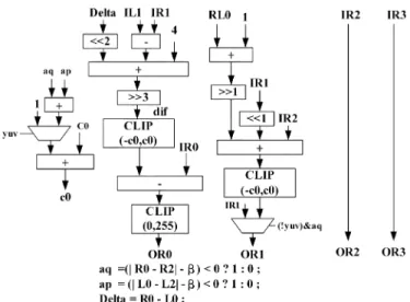
Fig. 7 shows the 8 pixels parallel-in parallel-out filter archi-tecture. Input pixels pass by normal filter and strong filter, and output 8 pixels are selected by boundary strength (Bs). Fig. 8 shows the name of a line data to be filtered by the parallel-in parallel-out filter. The strong filter and normal filter are shown in Figs. 9 and 10. Only the right parts are shown in the figure, since the left parts are symmetric to right parts. In the datapath of strong filter and normal filter, multiple input adders are imple-mented by carry save adder to speed up the addition operation.
As shown in Fig. 7, the filtering does not take place for edges with Bs equal to zero. For edges with nonzero Bs values. Two quantization-dependent parameters, referred to as and , are used to determine whether the input data is filtered. Filtering on a line of samples only takes place if the three conditions all hold true
If one of the three equation does not hold true, and the control logic will select the output of Bs .
C. Memory Organization
In the proposed computation flow, the deblocking operation uses horizontal-vertical interleaved scheduling. However, to support such an interleaved operation, the corresponding ar-chitecture shall transpose the 4 4 block immediately when
Fig. 9. Datapath of strong filter.
Fig. 10. Datapath of normal filter.
changing the filtering edges. The corresponding data path consists of a 4 4 shift buffer and a 4 4 transpose buffer. We assume that SRAM module is an ordinary one which has one 32-bits read port and one 32-bits write port. With this, we can transpose the 4 4 data blocks to support both horizontal filtering and vertical filtering on a parallel-in parallel-out de-blocking filter seamlessly.
The on-chip buffer first stores blk1 to blk4. Fig. 11 shows its data organization, where m is an integer number from 0, the number in the block denotes the block index and each block stores one 4 4 block data. Then, the same address location will be overwritten by new data resulting from blk6 to blk9, respectively. This will be repeated for each row of 4 4 blocks. Since data in-place is overwritten after reading out, no read-write conflict will occur.
D. Processing Schedule
Assume input data are four pixels (32 bits) per clock cycle, it
requires to process the
luma block of an MB without overlapping the data flow. Among them, 16 cycles to input data of Blocks 1 to 4 from external
Fig. 11. Organization of on-chip two port SRAM.
memory to on-chip memory before the start of data processing, to process edge to , 4 cycles to shift block from 4 4 shift buffer to 4 4 transpose buffer, 4 cycles to process edge , and 16 cycles to output data of Blocks 21 to 24 from on-chip memory to external memory, where is an integer number from 0 to 3. For two chroma
blocks, are required.
Thus, 320 cycles are required to process one MB.
For a more efficient processing schedule, we can save four cy-cles by overlapping the data loading cycy-cles of Block
from the external memory and data shifting cycles of Block from 4 4 shift buffer to 4 4 transpose buffer be-fore processing horizontal edge . For example, we need four cycles to shift the data of Blocks 9 to 4 4 transpose reg-ister. During the same four cycles, we can also move the data of Block 10 from external memory to 4 4 shift register. With this scheduling, the total cycle count is reduced to 300 cycles for one MB.
IV. IMPLEMENTATION ANDCOMPARISON
To evaluate the accuracy and the efficiency of the proposed architecture, the architecture is designed in Verilog and imple-mented by TSMC 0.25- m CMOS technology. The result has been verified with that from the reference software and all data are matched. The resulting hardware can achieve real-time 2K 1K (2048 1024) 30 Hz video at 73.73 MHz. The gate count is only 13.41K when synthesized at 100 MHz, excluding the memory cost. This design is for 8-bit data. However, it can be easily extended into wider word length to support other profiles. Table I compares our design with the state-of-art approaches in [6]–[10]. For filtering a MB, our design requires least memory size because of using the in-place architecture. Specifically, we have the smallest cycle count at worst case when processing a MB. The processing order of [7], though similar to the proposed one, has quite different architectures and thus higher gate count and cycle numbers. In [9], they use adaptive MB transmission scheme to early skip the edge data which is unnecessary to be filtered. However, its result is dependent on quantization param-eter (Qp), video content, and frame types.
V. CONCLUSION
In this brief, we contribute a full data reuse deblocking processing flow and its corresponding VLSI architecture for deblocking filter in H.264/AVC. By rearranging the data flow we can achieve high data reusability, and therefore reduce the required memory size. The major idea is to filter a vertical edge immediately followed by the filtering of a horizontal edge for a 4 4 block instead of whole MB. With a 4 4 transpose buffer, the aforementioned interleaved vertical and horizontal deblocking filtering can be easily realized. Thus, the
processing capability of the proposed architecture can operate very efficiently. The performance can meet high resolution, real-time processing applications and suitable to be integrated into H.264/AVC codec.
REFERENCES
[1] Y.-L. Lee and H. W. Park, “Loop filtering and post-filtering for low-bitrates moving picture coding,” Signal Process. Image Commun., vol. 16, pp. 871–890, 2001.
[2] S. D. Kim, J. Yi, H. M. Kim, and J. B. Ra, “A deblocking filter with two separate modes in block-based video coding,” IEEE Trans. Circuits
Syst. Video Technol., vol. 9, no. 2, pp. 156–160, Feb. 1999.
[3] Draft ITU-T Recommendation and Final Draft International Standard
of Joint Video Specification, ITU-T Rec. H.264/ISO/IEC 14496-10
AVC, Mar. 2003.
[4] P. List, A. Joch, J. Lainema, G. Bjøntegaard, and M. Karczewicz, “Adaptive deblocking filter,” IEEE Trans. Circuits Syst. Video Technol., vol. 13, no. 7, pp. 614–619, Jul. 2003.
[5] H.264/AVC Reference Software JM7.2. Jul. 2003.
[6] Y.-W. Huang, T.-W. Chen, B.-Y. Hsieh, T.-C. Wang, T.-H. Chang, and L.-G. Chen, “Architecture design for deblocking filter in H.264/JVT/ AVC,” in Proc. Multimedia Expo., Jul. 2003, vol. 1, pp. 693–696. [7] B. Sheng, W. Gao, and D. Wu, “An implemented architecture of
de-blocking filter for H.264/AVC,” in Proc. Int. Conf. Image Processing, Oct. 2004, vol. 1, pp. 665–668.
[8] M. Sima, Y. Zhou, and W. Zhang, “An efficient architecture for adaptive deblocking filter of H.264/AVC video coding,” IEEE Trans.
Consum. Electron., vol. 50, no. 1, pp. 292–296, Feb. 2004.
[9] S.-C. Chang, W.-H. Peng, S.-H. Wang, and T. Chiang, “A plat-form based bus-interleaved architecture for de-blocking filter in H.264/MPEG-4 AVC,” IEEE Trans. Consum. Electron., vol. 51, no. 1, pp. 249–255, Feb. 2005.
[10] C.-C. Cheng and T.-S. Chang, “An hardware efficient deblocking filter for H.264/AVC,” in Proc. Int. Conf. Consum. Electron., Jan. 2005, pp. 235–236.