Reducing the Impact of Mobile IP Handoff by
the Recorded Neighbor Information
Po-Jen Chuang
Department of Electrical Engineering Tamkang University
Tamsui, Taipei County Taiwan 25137, R. O. C. Email: [email protected]
Chi-Hua Hsieh
Department of Electrical Engineering Tamkang University
Tamsui, Taipei County Taiwan 25137, R. O. C. Email:[email protected]
Chih-Shin Lin
Department of Electrical Engineering Tamkang University
Tamsui, Taipei County Taiwan 25137, R. O. C. Email: [email protected]
Abstract―The routing protocol Mobile IP is introduced
in 1996 to facilitate wireless networking and mobile com-munication. The problem encounters Mobile IP is: When a mobile node (MN) hands off between different agents, packets may get lost or the node itself may get discon-nected. A number of handoff schemes have been proposed to improve the situation but can reduce only the impact of Mobile IP handoff in ideal topologies with enough signal overlapped areas. The goal of this investigation is to re-duce the handoff latency to attain seamless communica-tion even under tough topologies. By adding a recording feature to every agent to preserve the information of neighbor agents, our new scheme can help a migrating MN keep receiving packets during the handoff period to attain the desired seamless connection even in the toughest topologies.
Index Terms―Experimental evaluation, handoff latency,
mobile IP, recorded neighbor information, seamless handoff.
I. Introduction
Wireless and mobile computing is rising as one of the most promising and hotly pursued computing topics in recent years. As its application scope broadens with time (wireless Internet surfing and mobile phones are 2 handy examples), the demand
for more advanced technical development becomes urgent and critical. To facilitate wireless network-ing and mobile communication, the Internet Engi-neering Task Force (IETF) introduces Mobile IP, a routing protocol, which uses a static IP and a tem-porary IP to attain seamless connection when an MN moves between different domains [1-3]. That is, when moving between different domains, an MN can use the same IP address to maintain the usual packet routing and thus to avoid packet loss during domain crossing. Mobile IP is an important design with a congenital problem: When a mobile node (MN) hands off between different agents, packets may get lost – even the node itself may get disconnected. A number of new handoff schemes [4-11] attempt to solve the problem by reducing either the packet loss or handoff/registration la-tency to achieve seamless mobile communication. Though able to reduce the impact of Mobile IP handoff to a certain extent, these new schemes nevertheless need to dwell on ideal topologies in which the AP will have enough signal overlapped
a r e a s , a s F i g u r e
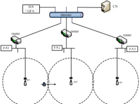
Figure 1. An example of ideal topologies.
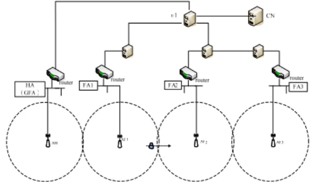
Figure 2. An example of tough topologies.
Figure 3. Another example of tough topologies.
1 shows. (Such ideal topologies are indeed hard to locate in reality.) For schemes using the link layer information to trigger, performance may degrade due to inability to receive immediate link layer triggering (as a result of insufficient signal over-lapped areas or terrain impediments), as shown in Figures 2 and 3.
This paper aims to reduce the handoff latency by adding a recording feature to every agent in the mobile system to preserve the information of neighbor agents. Based on the recorded neighbor information, our handoff scheme can duplicate and re-direct packets for the target agent, enabling a migrating MN to receive packets during the entire handoff period to attain the desired seamless con-nection. Such a design may not reduce the registra-tion time but will effectively reduce the number of lost packets during MN handoff. Simulation results show that, without requiring the link layer informa-tion, our new scheme is able to achieve seamless mobile communication even in tough topologies with insufficient or no signal overlapped areas.
This paper is organized as follows. A brief back-ground study is provided in Section 2 to facilitate further discussion. The new handoff scheme is in-troduced in Section 3. Section 4 gives the results of experimental evaluation. Section 5 concludes the paper.
II. Related Works
A. The Mobile IP Protocol
The Internet packet routing is conducted accord-ing to the network prefix routaccord-ing. Under such a routing principle, an MN will fail to maintain the usual packet routing when moving from its original domain to another – because of the difference in its network prefix number. The consequence is packet loss or even node disconnection. For improvement, IETF introduces a new routing protocol, the Mobile IP, which allows a migrating MN to use the same IP address to communicate with the outside world and thus to continue the usual packet routing while moving between different domains.
Mobile IP operates as follows. An MN in the home network will be assigned a fixed IP by the HA (the agent in the home network). When moving to a foreign network, it will be assigned a CoA –
Care of Address – by the FA (the agent in the for-eign network). CoA is a temporary IP, usually the FA IP address. With CoA, an MN roaming away from the home network can register through the FA to the HA. The HA will then set up a lifetime for such a registration to maintain the effectiveness and safety of the connection, and the MN will regularly register through the FA to the HA to secure the connection status.
When an MN in the FA area attempts to route a packet, the packet will be routed to the HA first, encapsulated there with a new header and then sent to the FA. After receiving such an encapsulated packet, the FA will de-capsulate it and redirect it to the MN [12, 13]. Any packet sent out from the MN should be delivered to its destination through the usual transmitting route by way of the FA – using the static IP provided by the HA as its source IP.
There remains a problem for Mobile IP: When an MN leaves the HA transmission range and enters an FA area, it can not keep receiving packets from the HA. After the link layer handoff, the MN re-ceives the agent advertisement from the FA, gets CoA and starts to register through the FA to the HA. Packets can be lost during the handoff period be-cause the MN will stop receiving packets from the HA until the registration is completed. The handoff latency can range from one to several seconds, sub-stantially degrading the real-time service quality (such as the real-time audio/video and voice calls) or even disconnecting the high-security protocol service.
B. Existing Handoff Schemes
A number of recent studies have tackled with the above handoff issues and turned over different schemes to improve the Mobile IP protocol.
The Hierarchical MIP (HMIP) [4, 11]
HMIP attempts to reduce the handoff latency by enhancing the efficiency of registration. It first di-vides FA’s into several groups and selects an up-stream node from each group as the cluster head or the gateway foreign agent (GFA). In the same group, when an MN migrates to a different FA and starts the registration process, the registration re-quest will be sent to the group GFA instead of to the HA. This cluster scheme can save the
tion time (especially when the MN moves far away from its HA) because the registration packet will be sent to the closely located GFA – instead of the distant HA – to save the round-trip time of packet transmission between the GFA and HA.
The following are 3 feasible ways to reduce the packet loss rates during mobile IP handoff: Packet buffering, link layer triggering and engaging multi-ple network interfaces.
Packet Buffering [5, 6]
In packet buffering, the original FA (oFA) will duplicate a temporary file and store it while deliv-ering the packet to the MN. When the MN enters a new FA (nFA) and gets handoff, the nFA will in-form the oFA of the current situation. Receiving the information, the oFA will deliver the temporary packet to the nFA and then to the MN. Such an ap-proach may avoid the handoff packet loss, but (1) the appropriate temporary storage size is hard to decide and (2) the temporarily stored packet will overflow if the MN spends a long time to reach the nFA.
Link Layer Triggering [7]
This approach uses the link layer information of the FA to trigger registration. That is, when an MN is about to leave its HA, it will start the registration process right upon receiving the link layer informa-tion of the FA. Being able to grasp the precise time to trigger up the registration can effectively reduce the Mobile IP latency.
Engaging the Multiple Network Interfaces [8, 9]
This approach usually involves using multiple network cards, that is, an MN needs to have multi-ple base station communication equipments, such as two wireless cards. With double network cards, a migrating MN can use one card to maintain com-munication with the oFA and the other card to reg-ister to the HA (through the nFA) while moving to a signal overlapped area of two base stations and receiving signals from the nFA. In the overlapped area, the MN can still receive packets by the first card before completing its registration to HA. After registration is finished, the HA will suspend the communication by the first card and redirect pack-ets to the nFA. The MN henceforth starts to receive incoming packets by the second network card.
In the above handoff schemes, HMIP [4] adopts regional (clustering) registration to reduce the re-quired registration time; the packet buffering ap-proach [5, 6] attempts to achieve seamless transfer by adapting the buffer and redirecting the packets; while the other approaches [7-9] try to pursue seamless connection using multiple network inter-faces or link layer triggering. These approaches will reach the goal of seamless transfer only under ideal topologies. If put to work under undesirable environments – such as those in Figures 2 and 3, they will face challenges of packet loss. For exam-ple, an insufficient signal overlapped area or certain signal impediments may keep an MN from taking immediate or necessary actions, resulting in packet loss and communication interruption. On the other hand, employing dual network cards might be an effective way to pursue the desired seamless con-nection, but it needs doubled cost – which is indeed infeasible when we consider the currently very competitive pricing of communication products.
III. SARNI – the Proposed New Handoff Scheme To attain seamless connection for the link layer handoff situations, this paper presents an effective new handoff scheme – the Seamless Approach with Recorded Neighbor Information (SARNI) – which features an information recording design and is able to work out even in very tough topologies. Our seamless approach takes the following as its basis: (1) An MN can receive packets from the nFA be-fore leaving the oFA [7] – to avoid communication interruption and (2) the locations of agents are fixed after installation – to build up a neighbor ta-ble (N_tata-ble). Based on the built N_tata-ble, the HA can use the recorded neighbor information to du-plicate a packet and transfer it to the nFA. A roam-ing MN can thus receive packets from the nFA to achieve seamless connection during the whole handoff period: leaving the oFA – entering the nFA (handoff starts) – registering to the HA – complet-ing registration. Involvcomplet-ing no link layer triggercomplet-ing, the proposed SARNI approach can work disre-garding the sizes of the overlapped area of two base stations or any environmental barriers.
A. Establishing the N_table
proach, employed mainly to record the information of neighbor agents so that they can learn about each other’s information and utilize the information to reach seamless connection in the handoff situations. When agents are first installed, they actually have no way to learn about each other’s information. Our approach can help with it – through the usual handoff/registration process every migrating MN must undergo when moving across different agents.
Here is the way it works. When a newly installed MN moves from the oFA to the nFA, the N_table of either the oFA or the nFA does not keep each other's information. By this stage, the MN will carry out the general registration procedure of the Mobile IP protocol (Figure 4). After leaving the oFA and enters the transmission scope of the nFA, the MN starts to register to the HA through the nFA. Upon receiving the registration request (from the nFA), the HA will issue a message of Neighbor-Rec – with the nFA IP, MAC address and nFA channel – to the oFA, and also a message of oFA NeighborRec – with the oFA IP, MAC address and oFA channel – to the nFA (Figure 5). Receiving such a NeighborRec message, the oFA will check its N_table: If the message is already in the record, ignore it; if not, add it in (Figure 6). Thus, using the
MN oFA nFA HA RegRly NeighborRec RegReq NeighborRec RegReq
Figure 4. Building up the neighbor tables of agents.
recorded neighbor information in the N_table of each FA, a migrating MN can carry out the essen-tial packet routing to attain the desired seamless transmission.
Note that under our SARNI approach, an MN can still lose packets in its initial migrating process when the information of the oFA and nFA is not yet recorded in each other’s N_table. That is, when SARNI is first launched, a migrating MN may face packet loss before completing its registration to the HA. However, soon after the roaming MN begins to fetch information recorded in the N_table of dif-ferent agents, the approach will secure very satis-fying seamless connection for the MN (to be dem-onstrated in the following).
Received RegReq? Yes No Transmit NeighborRec to nFA and oFA Transmit RegRly
to nFA
Is the record already in the N_table?
Add the record in the N_table. Received NeighborRec? Yes No No Yes The strength of signal sent from the oFA lower than 5%?
send a BufTrig message to the oFA Yes No Rreceived BufTrigAck? Yes No
Figure 5. The HA flowchart of building a N_table.
Figure 6. The FA flowchart of building a N_table.
Figure 7. The MN flowchart of packet redirecting.
Does N_table have the recorded information of the
nFA?
Use BufferReq to inform the HA of duplicating the packet and redirecting it
to the nFA. Received BufTrig? Yes No Yes No Deliver PreBufSol to nFA(s), and send BufTrigAck to MN. Received BufferReq? Yes No Duplicate and encapsulate the MN's packets and then redirect
them to the nFA.
Received BufSolRly? Yes
No
Figure 8. The oFA flowchart of packet redirecting.
Figure 9. The HA flowchart of packet redirecting.
Figure 10. The nFA flowchart of packet redirecting.
B. Packet Redirecting
While moving from the oFA to the nFA, the MN will keep comparing the signal strength sent from the oFA: If the strength goes lower than 5% (or a continuing reduction until < 5%), the MN will send a BufTrig message to the oFA and await BufTri-gAck. If not receiving BufTrigAck, it will keep re-sending BufTrig – to avoid the chance of packet loss (Figure 7).
As mentioned, the goal of this research is to help migrating MN’s attain seamless connection in such awkward timing situations as (1) when an MN leaves the oFA for the nFA but not yet completing its registration to the HA or (2) when an MN al-ready enters the nFA scope but not yet walks out of the oFA transmission range. Under such situations, the oFA will check its own N_table after being triggered by the message of BufTrig: If its N_table has the recorded information of the nFA (indicating the nFA is a neighbor of the oFA), it will send BufferReq to the HA by wire transfer (Figure 8). That is, the oFA will use BufferReq to inform the HA of duplicating the packet and redirecting it to the nFA.
Each BufferReq message contains (1) MN IP address, (2) MN MAC address and (3) nFA IP ad-dress. If there are multiple neighbor records in the N_table, all will be sent out by one BufferReq. If the oFA has no neighbor information in its N_table, it will neglect BufTrig. Then the oFA will send the MN a GetChn message with the channels which the neighbor FAs (in the N_table of oFA) will use to transmit packets to the MN. Such a GetChn mes-sage will help the MN find the correct channel for transmission during link-layer handoff to save the channel scanning time when entering a new FA.
After receiving the BufferReq message, the HA will respond by sending BufTrigAck to the MN and then delivering PreBufSol to the nFA through wire transfer. The content of PreBufSol includes the MN IP and MAC address, which the nFA can use to es-tablish the route to the MN (Figure 9).
After receiving the PreBufSol message, the nFA will use its information to set up a corresponding ARP routing table and then wire transfer a BufSol-Rly message to the HA so that the HA can begin to transmit (Figure 10).
The HA first duplicates and encapsulates the MN's packets and then redirects them to the nFA. Receiving the encapsulated packets, the nFA will de-capsulate them and then transfer the de-capsulated packets to the MN. In such a process, the oFA will continue to deliver packets to the MN until the MN leaves its transmission scope.
C. The Flowchart of Performing SARNI –
Illus-trated by an Example
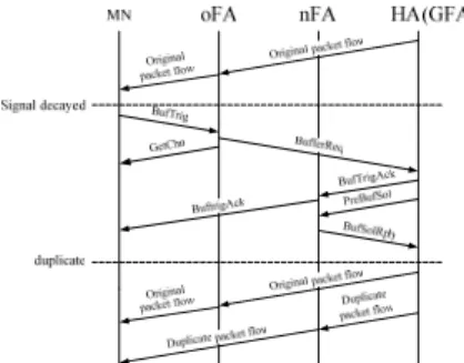
Figure 11. The flowchart of operating the SARNI approach.
The flowchart of performing SARNI
Figure 11 gives the complete flowchart of oper-ating our SARNI approach. The flowchart helps exhibit how the proposed approach utilizes the re-corded neighbor information in agents to accom-plish the desired seamless communication. As the flowchart indicates, when an MN leaves the oFA, enters an nFA and starts the registration process, the nFA will continue to receive the encapsulated packets from the HA, de-capsulate the packets and then send them to the MN. Amid this registration process, transmission between the nFA and MN will not be affected by packet exchange among the MN, oFA and nFA. That enables the MN to con-tinue receiving packets from the HA even in hand-off situations – thus achieving seamless connection. Once the MN completes its registration to the HA, the HA will stop the duplicating/redirecting action to restore the normal Mobile IP transmission.
An Example Case
An example of running the SARNI approach is given in Figure 12 to assist understanding.
Figure 12. The topology of the MIP environment.
The initial stage: Assume FA1 (AP1), FA2 (AP2)
and FA3 (AP3) are each installed in locations (1000, 0), (2000, 0) and (3000, 0) with a broadcasting range of 550m and user A moves from AP1 in a straight line and at speed 15m/s toward AP3 with a handheld PDA. (The assumed straight-line move-ment will ensure that user A moves to an area cov-ered either by AP1, AP2 or AP3). During the movement, the related wireless communication protocol in the PDA will keep measuring the signal strength from AP1. When the signal strength de-grades to less than 5%, the PDA immediately sends a BufTrig to FA1 – the agent of AP1. Receiving the BufTrig message, FA1 checks its N_table for neighbor information but finds nothing there be-cause it is newly installed. Having no neighbor re-cords in the N_table, FA1 then ignores the BufTrig without taking further actions. Abort the follow-up steps of SARNI.
The follow-up steps: When user A moves to
loca-tion (1551, 0) leaving the transmission range of AP1, it no longer receives packets from AP1 – the PDA is hence disconnected. The PDA then files a registration request to the HA (GFA) by way of FA2. Receiving such a request from FA2, the HA will send NeighborRec containing FA2 to FA1 and NeighborRec containing FA1 to FA2 – immediately following the registration reply to FA2. Upon at-taining NeighborRec from the HA, either FA1 or FA2 will look up its own N_table: If the content of the received NeighborRec is already there, ignore the message; if not, add it to the N_table.
Similarly, when user A moves to location (2522.5, 0) where the signal strength from FA2 drops below 5%, the PDA will send a BufTrig to FA2. Receiving the BufTrig, FA2 – whose N_table
stores the information of FA1– will send a Buffer-Req containing FA1 to the HA. The HA then moves on to duplicate the packets destined to user A and forward them to FA1. Right before starting to du-plicate and forward the packets, the HA first sends a PreBufSol to FA1 asking FA1 to construct the required routes and corresponding CoA.
The HA will start packet duplication and for-warding only after receiving a BufSolRply from FA1. It will move on to duplicate and encapsulate all packets that are destined to user A, and forward them to FA1 which then de-capsulates the packets and forwards them to user A. Such duplicating and forwarding will not affect the original mechanism of the HA. It can still send the packets to FA2 through the original route and forward them to user A by way of FA2.
The problem is, by this moment user A has roamed into the transmission range of a new agent – AP3 (FA3) – and still faces service inter-ruption. The process of constructing neighbor re-cords strikes off again. That is, while leaving FA2 to reach FA3, user A will send a registration request to the HA through FA3. The HA then responds by sending a NeighborRec packet containing FA3 to FA2 and another NeighborRec packet containing FA2 to FA3 (for both FA’s to record each other’s information). Note that after user A finally com-pletes the registration, the HA (GFA) will stop du-plicating and forwarding the packets (to be routed to user A) to FA1.
By now, FA2 is recorded in the N_tables of FA1 and FA3, while FA1 and FA3 are recorded in the N_table of FA2. Then, if another user B, moves along user A’s straight-line route from location (1000, 0) to (3000, 0), the wireless communication protocol in the PDA of user B will keep measuring the signal strength coming from AP1 during the entire movement. When the signal strength de-grades below 5%, user B will send a BufTrig to the agent of AP1 – FA1. Receiving the BufTrig, FA1 which has FA2 in its N_table will respond by sending a BufferReq containing FA2 to the HA. Before going on to duplicate and forward those packets (destined to user B) to FA2, the HA (GFA) will first send FA2 a PreBufSol to urge it into con-structing the needed routes and corresponding CoA.
FA2 then replies by sending the HA a BufSolRply – which contains the needed routes and CoA – to get the HA into duplicating, encapsulating and for-warding the packets to FA2. Receiving the encap-sulated packets, FA2 moves on to de-capsulate the packets and forward them to user B. The HA will meanwhile keep sending these packets to FA1 (by the original route) and further forwarding them to user B.
Packet duplication helps to reach the goal of seamless transmission – despite users may receive duplicated packets. Following the above example, when user B moves to the range of FA2 and starts the original Mobile IP handoff/registration mecha-nism, the HA can still take advantage of NeighborRec to exchange neighbor information for FA1 and FA2. However, since FA1 and FA2 are already in each other’s N_tables, the NeighborRec will be ignored. As soon as user B finishes registra-tion, the HA will stop packet duplicat-ing/forwarding and use the original standard Mo-bile IP mechanism to transmit packets – that is, packets to user B will be transferred by FA2.
Then when user B moves from location (2495, 0) to (2522.5, 0) where the signal strength coming from FA2 drops below 5%, it again sends a BufTrig to FA2. With FA1 and FA3 in the N_table, FA2 thus sends a BufferReq containing FA1 and FA3 to the HA. The subsequent process goes as specified previously: The HA first sends a PreBufSol to FA1 and FA3 and will not start duplicating or forward-ing the packets to FA1 and FA3 before receivforward-ing BufSolRply from them. The HA will maintain such packet duplicating/forwarding until user B enters the range of FA3 and completes its registration (through FA3). After registration is finished, the packets to user B will be encapsulated by standard Mobile IP, sent to FA3 and then passed over to user B. Seamless transmission is hence achieved – be-cause when user B leaves AP2 to enter AP3 and undergoes the registration process (i.e., remains in handoff), it can still receive the duplicated packets from the HA via FA3.
IV. Experimental Evaluation
A. The Simulation Model
This research adopts ns2 [14] as the simulation
platform. Figure 13 displays the conducted simula-tion environment in which AP0, AP1, AP2 and AP3 are respectively located at coordinates (0, 2), (1000, 2), (2000, 2) and (3000, 2). The antenna parameter is “TwoRayGround”, with a transmission radius of 550m, and the AP overlapped area is 100m. The wire connection between nodes is a two-way bandwidth 5Mbits/s, with a delay of 2ms. The AP and MN MAC protocol is 802.11 and the routing protocol is DSDV. The moving speed of an MN is 15m/s, starting from 0 sec at AP0 (0, 2) traversing toward AP3 (3000, 2). The test communication is the UDP format CBR, with the packet size = 500 bits and the packet inter-transmission interval = 5ms. Different from general Ad Hoc networks, the routing table in a wireless network must have a higher refresh rate to meet the demands of Mobile IP – we therefore adjust the DSDV routing table update cycle to 0.2 seconds.
Figure 13. The simulation topology.
As stated, our SARNI approach will first estab-lish the neighbor information which is to be re-corded soon after transmission begins. That is, at the moment when an MN starts its first migration, there exist no such neighbor records to assist the needed packet transfer – which places the MN un-der the risk of facing the handoff interruption prob-lem in the very beginning of the first migration. The situation is just like using the Mobile IP pro-tocol, but in our approach it is exactly the opportu-nity to start establishing neighbor records for the agents. To obtain more distinctive result, this simu-lation adopts the SARNI approach with established neighbor tables to conduct performance evaluation and comparison with Mobile IP and other related schemes.
20200 20300 20400 20500 20600 20700 20800 20900 21000 21100 202.6 203.1 203.6 204.1 204.6 time(s) se que nc e nu m be r of pa ck et 33300 33400 33500 33600 33700 33800 33900 34000 34100 34200 34300 268.1 268.6 269.1 269.6 270.1 270.6 271.1 time(s) se que nc e num be r of pa cke t
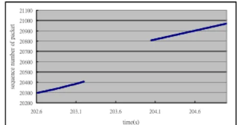
Figure 14. The UDP performance of Mobile IP (when the MN leaves FA1 to enter FA2).
Figure 15. The UDP performance of Mobile IP (when the MN leaves FA2 to enter FA3).
Figure 16. The UDP performance of our SARNI approach.
B. The Simulation Results
Seamlessness
Figures 14 and 15 give the handoff interruption of the Mobile IP protocol. In Figure 14, when the MN leaves the transmission range of FA1 (at 203.2 seconds) and fails to complete registration in this time period, it will stop receiving packets from the HA – service is then interrupted. It is until the MN and FA2 complete the registration that packets start to be sent from the HA to FA2 and then from FA2 to the MN. The similar situation happens again when the MN moves away from FA2 at 269.8 sec-onds.
In Figure 15, when the MN leaves FA2 to enter the transmission region of FA3, it will continue to receive packets from the HA (through FA3) only when the handoff is over, i.e., when the registration is finished. Before that, it receives no packets from the HA.
Figure 16 displays the improved packet trans-mission by employing our SARNI approach to handle the handoff situation in Figures 14 and 15. As our approach allows the HA to duplicate and redirect packets to the nFA, a migrating MN which leaves the oFA and has not completed its registra-tion to the HA can still receive packets from the HA via the nFA. Such a mechanism helps avoid service interruption during handoff and enables the MN to keep receiving packets from the HA without inter-ruption – either when it leaves FA1 to enter FA2 or leaves FA2 to enter FA3. Seamless connection is thus achieved.
About the Overlapped Area
The performance of handoff schemes involving
the link layer information will vary with different sizes of signal overlapped areas between 2 access points. To observe the impact of differently sized AP overlapped areas, this simulation gradually re-duces the size of such an area from 100m to 0m – by 10m at each reduction. We also adjust the MN roaming routes from 2 to 10 handoffs between the original FA1 and FA3. The average disconnection time in the following results will help demonstrate how different signal overlapped areas will influ-ence the performance of handoff schemes.
The Mobile IP Protocol: For Mobile IP, as the
re-sult in Figure 17 shows, the sizes of overlapped ar-eas and the interruption time are not in linear status. This is because in the standard Mobile IP handoff when an MN leaves the oFA and loses the connec-tion in-between, it can start the registraconnec-tion process via the nFA.
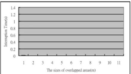
Our SARNI Approach: For our SARNI approach
(which is proposed to improve Mobile IP), when an MN moves away from the oFA but remains within the nFA transmission region, it can always receive packets redirected from the HA. The new approach will start operation all at once (the trigger point) when an MN detects the progressively decreasing signal strength goes below 5% and requests the HA to duplicate and redirect packets.
Take overlapped area size 0m as an example. The AP covering radius is 500m and the trigger point is located 475m away from the AP. For the case in Figure 11, packet duplication begins after 6 messages route among the HA, MN and nFA. The routing time for the six messages is 0.005 (the time interval) x 6 = 0.03(s).
0 0.2 0.4 0.6 0.8 1 1.2 1.4 1 2 3 4 5 6 7 8 9 10 11 The sizes of overlapped areas(m)
In te rru ptio n T im e(s ) 0 0.2 0.4 0.6 0.8 1 1.2 1.4 1 2 3 4 5 6 7 8 9 10 11 The sizes of overlapped areas(m)
In te rr up tio n T im e( s) 0 0.2 0.4 0.6 0.8 1 1.2 1.4 1 2 3 4 5 6 7 8 9 10 11 The sizes of overlapped areas(m)
In te rr up tio n T im e(s )
Figure 17. Disconnection time for Mobile IP under different signal overlapped areas.
Figure 18. Disconnection time for LLA-AP under different signal overlapped areas.
Figure 19. Disconnection time for SARNI under different signal overlapped areas.
That is, after 0.03 seconds the HA starts to du-plicate the packets and transfer them to the nFA. As the trigger point for the MN is 475m from the AP, after 0.03 seconds (i.e., when the nFA receives the duplicated and redirected packets from the HA and prepares to pass them over to the MN), the MN will be at the location of (475 + 15 x 0.03 = 475.45). Based on this fact, we believe that even without any signal overlapped area, our approach can still attain the desirable “seamless” communication, not to mention the totally uninterrupted connection achieved when there are signal overlapped areas (10m to 100m). Note that with the overlapped area = 0, SARNI generates a 0.11-second interruption among the 10 conducted runs, which makes an av-erage disconnection of 0.011 sec. As the packet in-terval = 0.005 sec, 0.011 sec is approximately the routing time for 2 packets – negligible indeed when compared to the overall network data transmission.
LLA-AP [8, 9]: Employing two network cards to
communicate respectively with the oFA and nFA to achieve seamless connection, LLA-AP appears to be the most robust among the link-layer-trigger protocols. The result in Figure 18 shows that with the signal overlapped area = 0m, the average hand-off disconnection time for LLA-AP is 0.56 sec, al-most equaling the 0.65 sec. of Mobile IP. It happens because without any overlapped area, LLA-AP is forced into handoff when its first card loses con-nection to oFA while the second card is still waiting for the signal from the nFA to start registration. For both LLA-AP and Mobile IP, the time required for the link layer handoff and network layer handoff should be the same – which helps explain when the overlapped area = 0, our simulation produces al-most equal disconnection time (0.56 sec. vs. 0.65
sec.) for both protocols. Compared to the 0.56 sec. of LLA-AP, the 0.011 sec. of our approach (shown in Figure 19) – 1/50 of 0.56 – is quite favorable and acceptable.
When the signal overlapped area increases from 10m to100m, LLA-AP is expected to reach seam-less connection by its multi network cards. It nev-ertheless continues to produce some disconnec-tion – because its two network cards compete against each other for transmission. For the proto-col, when the second network card completes reg-istration by the nFA, the oFA will end communica-tion with the first network card. The problem is: the first card may keep listening to the radius signal from the oFA in the overlapped area to trigger the next registration. In such a situation, when the MN actually completes registration to the HA via the oFA, it might have left the transmission range of the oFA and lost connection. The MN now will have to wait until the second card finishes registra-tion to the HA again to restore communicaregistra-tion. In bigger overlapped areas, competition between the two cards gets even more obvious.
In Tough Topologies
The goal of this simulation is to evaluate the performance variance for LLA-AP and SARNI when they encounter tough topologies (in which the AP does not have enough or any signal over-lapped area) and fail to function immediately.
Our SARNI Approach: Assume that due to some
unpredictable factors, SARNI completes the action of sending Buftrig to the HA by 1 second delay. Let’s take Figure 11 as an example to illustrate the situation. In this case, with no signal overlapped area, the HA will start to duplicate packets after 6
0 0.2 0.4 0.6 0.8 1 1.2 1.4 0 10 20 30 40 50 60 70 80 90 100
The sizes of overlapped areas(m)
In te rr upt ion T im e( s) LLA-AP SANRI 0 20000000 40000000 60000000 80000000 100000000 120000000 B andw idth C on su mpt ion (B yt e) Mobile IP SANRI LLA-AP
Figure 20. Handoff interruption for SARNI and LLA-AP under 1-sec delay and varied signal over-lapped areas.
Figure 21. Bandwidth consumption of different handoff schemes.
Figure 22. The UDP performance of IPH (when the MN leaves FA1 to enter FA2).
Figure 23. The UDP performance of IPH (when the MN leaves FA2 to enter FA3).
messages route through the HA, MN and nFA. Adding the routing time for the 6 messages 0.03 sec. (the time interval 0.005 sec. x 6) and the delay time 1 sec., the HA will start packet duplication at 1.03 sec. – i.e., when the MN moves from 475m (where it first triggers SARNI) to 490.45m (475m + 15m x 1.03). By the time the MN arrives at AP490.45, it has not left the oFA but the nFA has already received the duplicated-redirected packets from the HA and gets ready to transmit them to the MN. The consequence is: The SARNI approach has completed its operation while the MN has not yet left the oFA. As Figure 20 shows, when the over-lapped area = 0, SARNI generates 3 times of off latency (0.18, 0.12, 0.10 sec.) among 10 hand-offs, yielding a 0.04-sec. average delay. This is in-deed a slight performance gap from our original expectation (that SARNI should be seamless) and we consider it a result of using ns2 to simulate the very practical environment.
LLA-AP: Figure 20 also gives the average
discon-nection time of LLA-AP when put into work with
1-sec. delay. As we can see, LLA-AP produces the same disconnection time as Mobile IP at signal overlapped area = 10m, and when the overlapped area further shrinks to 0m, the disconnection time for LLA-AP gets even longer. In fact, as our simu-lation result reveals, LLA-AP faces transmission interruption in most of the conditions (overlapped areas = 20, 30, 50, 70, 80, 90, 100m) out of the same reason specified in our previous discussion: Its two network cards compete against each other for transmission. The result in Figure 20 also manifests a key point – our SARNI approach per-forms better than the LLA-AP approach even under 1-sec delay. In the worst situation when the signal overlapped area = 0, the disconnection time of LLA-AP is far higher (31times) than that of SARNI.
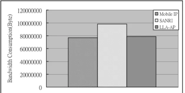
Bandwidth Consumption
Compared with Mobile IP, SARNI consumes more bandwidth because it starts packet duplication and redirection, and retains the original data stream
before leaving the oFA. Besides, if the oFA has many records, SARNI will duplicate the packet and pass it along to all FA’s appearing in the records – despite the fact that the MN moves only towards one direction – thus wasting extra bandwidth. In our calculation of the total amount of data in wire-less transmission, SARNI takes 98090380 bytes which is 27% higher than 77015572 bytes of Mo-bile IP and 25% higher than 78512400 bytes of LLA-AP, as depicted in Figure 21.
Other Discussions
The target of this discussion is the Indirect Pro-active Handoff (IPH) scheme which is based on a neighbor record mechanism similar to ours [15]. The IPH scheme triggers its handoff mechanism when an MN is about to leave the transmission range of the oFA: The HA will first redirect and buffer the packet to the nFA which will hold the packet until the registration is completed and then forward it to the MN. This scheme can reduce packet loss, increase throughput but achieve no seamless connection. In its design, immediately after triggering, the packets originally sent through the oFA to the MN are now redirected to and stored in the nFA. Thus before completely roaming out of the oFA radius, the MN will receive no more pack-ets. When there exists such a period during which the MN stops getting packets from the HA – trans-mission gets interrupted. For further reference, the performance of this scheme is also simulated and the results are given in Figures 22 and 23.
V. Conclusion
Mobile IP, a routing protocol, uses a static IP and a temporary IP to attain seamless connection for MNs in the handoff status. When an MN hands off between different agents, plenty of packets may get lost or the node itself may get disconnected. Exist-ing handoff schemes endeavor to solve the problem by reducing either the packet loss or the hand-off/registration latency to achieve seamless com-munication. These handoff schemes can work out only under “ideal” topologies where the AP has enough signal overlapped areas to facilitate trans-mission. In “tough” topologies without enough or any overlapped areas, their performance degrades.
To attain seamless connection for the link layer
handoff situations, this paper presents an effective new handoff scheme – the Seamless Approach with Recorded Neighbor Information (SARNI) – which features an information recording design and is able to work out even under tough topologies. The new seamless approach builds up a neighbor table (N_table) for each agent to record its neighbor formation. Based on such recorded neighbor in-formation, an agent can duplicate packets and redi-rect them to the nFA while an MN migrates to a new domain. The migrating MN can thus receive packets from the nFA to achieve seamless connec-tion during the whole handoff period. Involving no link layer triggering, the SARNI approach can al-ways achieve seamless communication – disre-garding the sizes of signal overlapped areas of two base stations or any environmental barriers. Simu-lation results show that at the expense of more bandwidth consumption, our new scheme is able to outperform other seamless handoff schemes – in terms of handoff latency or disconnection time – even under the toughest topologies.
REFERENCE
[1] C. Perkins, “IP Mobility Support for IPv4,”
IETF RFC 3344, Aug. 2002.
[2] C. Perkins, “IP Mobility Support”, IETF RFC
2002, Aug. 1996.
[3] D. Saha, A. Mukherjee, I. S. Misra, M. Chak-raborty, and N. Subhash, “Mobility Support in IP: a Survey of Related Protocols,” IEEE
Net-work, pp.34-40, Dec. 2004.
[4] E. Gustafsson, A. Jonsson, and C. Perkins, “Mobile IP Regional Registration,” Internet
Draft, draft-ietf-mobileip -reg-tunnel-06.txt,
June 2004.
[5] C. Perkins, and K. Y. Wang, “Optimized Smooth Handoffs in Mobile IP,” Proc. 4th
IEEE Symp. on Computers and Communica-tions, July 1999, pp.340-346.
[6] T. Takahashi, J. Harju, K. Asatani, and H. To-minaga, “Inter-domain Handover Scheme Based on Forwarding Router Discovery for Mobile IP Networks,” Proc. 2005 IEEE Int’l
Conf. on Wireless Communications and Net-working, Mar. 2005, pp.409-1414.
[7] K. E. Malki, “Low-Latency Handoffs in Mo-bile IPv4,” IETF RFC 4881, June 2007.
Link Layer Assisted Fast Handoff Scheme Us-ing the Alternative Path Approach,” Proc. 20th
Int'l Conf. on Advanced Information Network-ing and Applications, Apr. 2006, pp.485-490.
[9] T. Min, T. Lin, K. Jianchu, “A Seamless Hand-off Approach of Mobile IP Based on Dual-link,” Proc. 1st Int'l Conf. on Wireless
Internet, July 2005, pp.56-63.
[10] J. Kempf, “Supporting Optimized Handover for IP Mobility Requirements or Underlying Systems,” Internet Draft, draft-manyfolks-l2- mobilereq-02.txt, June 2002.
[11] R. Hsieh, and A. Seneviratne, “A Comparison of Mechanisms for Improving Mobile IP Handoff Latency for End-to-End TCP,” Proc.
9th Annual Int’l Conf. on Mobile Computing
and Networking, Sep. 2003, pp. 29-41.
[12] C. Perkins, “IP Encapsulation within IP,” IETF
RFC 2003, Oct. 1996.
[13] C. Perkins, “Minimal Encapsulation within IP,”
IETF RFC 2004, Oct. 1996.
[14] Network Simulator version 2, http://www.isi. edu/nsnam/ns/tutorial/.
[15] M. Mansourme, J. E. Mellor, and I. Awan, “Improve Handoff HMIP Scheme Using Loca-tion InformaLoca-tion,” Proc. 3rd Int'l Conf. on
In-formation and Communication Technologies: From Theory to Applications, Apr. 2008,