國 立 交 通 大 學
機械工程學系
碩士論文
貧油潤滑下深孔鑽刀桿受側向制振之行為研究
The shaft behavior of deep hole drilling tool under lateral vibration
control with minimum quantity lubrication
研 究 生 : 陳重延
指導教授: 秦繼華 教授
貧油潤滑下深孔鑽刀桿受側向制振之行為研究
The shaft behavior of deep hole drilling tool under lateral vibration
control with minimum quantity lubrication
研 究 生:陳重延 Student:Chung-Yen Chen
指導教授:秦繼華 Advisor:Jih-Hua Chin
國 立 交 通 大 學
機 械 工 程 學 系
碩 士 論 文
A ThesisSubmitted to Department of Mechanical Engineering College of Engineering
National Chiao Tung University in partial Fulfillment of the Requirements
for the Degree of Master
in Mechanical Engineering
June 2009
Hsinchu, Taiwan, Republic of China
貧油潤滑下深孔鑽刀桿受側向制振之行為研究
學生:陳重延 指導教授:秦繼華博士
國立交通大學機械工程學系
摘要
深孔技術可適用於鑽銷孔深度直徑比較高的孔加工,本文研究BTA (Boring and Trapanning Association) 深孔鑽受側向制振及貧油潤滑下的刀桿行為,其中使用磁流變 阻尼器來進行制振。本文基於應用運送流體的管子及Bernoulli-Eulerian理論,建立一個 貧油潤滑下深孔鑽刀桿在受側向制振的動態方程式,藉此探討刀桿受到流體流動及阻 尼器影響下的特徵值。
The shaft behavior of deep hole drilling tool under lateral
vibration control with minimum quantity lubrication
Student: Chung-yen Chen Advisor:Jih-Hua Chin
Department of Mechanical Engineering
National Chiao Tung University
Abstract
Deep hole technique can be used to drill hole with high depth-diameter-ratio. The propose of the study is investigated the shaft behavior of BTA (Boring and Trapanning Association) deep hole drilling under lateral vibration control with minimum quantity lubrication. The lateral vibration is controlled by magneto-rheological damper. The study is based on theories of pipes conveying fluid with a velocity and Bernoulli-Eulerian theory. The eigenvalues of the shaft effected by fluid flow and damper is investigated.
Acknowledgment
I would like to give my sincere thanks to my advisor, Dr. Jih-Hua Chin, for his continuous guidance and inspiration throughout the period of this study and research. The concern and support from my parents is also of great significane and important to me. Finally, I heartily appreciate all friends and classmates who ever helped and encouraged me during this years.
Contents
Abstract (in Chinese) i Abstract (in English) ii Acknowledgment iii
List of Tables vi
List of Figures vii
Nomenclatures viii
Chapter 1 Introduction 1
...
1.1 Motivation of the Study 1
...
1.2 Purpose of the Study 2
... 1.3 Overview 2 ... 1.3.1 Overview of BTA 2 ... 1.3.2 Overview of MQL 3 ... 1.3.3 Overview of MRF 4 ... 1.4 Literature Review 5 ...
1.4.1 Literature review of BTA 5
...
1.4.2 Literature Review of MQL 7
...
1.4.3 Literature Review of MRF 7
Chapter 2 Equation of Motion 10
...
2.1 Properties of Magneto - Rheological Fluids 10
...
2.2 Effect of MQL 11
...
2.3 Equation of Motion Without Damper 12
...
2.4 Simplified Equation of Motion With Damper 14
Chapter 3 Method of Solution 17
...
3.1 Eigenvalues of the Equation of Motion 17
...
3.2 Sensitivities of Eigenvalues 20
...
4.1 Calculate the Eigenvalue Problem 24
...
4.2 Sensitivity of the Eigenvalues of the Shaft with Damper 27
...
4.3 Shaft Behavior Effected by Placement of Damper 28
...
4.4 Shaft Behavior Effected by MQL Applying 29
Chapter 5 Conclusions 32
List of Tables
Table 3.1 The values of βr...22
Table 4.1 Undamped natural frequencies of the tool shaft without fluid flow U= 0 c = 0 ...25
Table 4.2 Damped Natural Frequencies of the Tool Shaft without fluid flow U= 0 c = 100 ...25
Table 4.3 Natural Frequencies of the shaft without damper with fluid U= 9.625m / sec , c = 0 ...26
Table 4.4 Damped Natural Frequencies of the tool shaft with fluid when damper placed at c= 100N / (m / s) ,U = 9.625m / sec ...26
Table 4.5 Eigenvalues due to the change of the damping constant c byΔc...27
Table 4.6 Eigenvalues due to the change of the damper attachment point α by Δα ...28
Table 4.7 Natural frequency due to placement of damper ...29
Table 4.8 Damping ratio due to placement of damper ...29
Table 4.9 Natural frequency due to the ratio of gas to fluid...30
Table 4.10 Damping ratio due to the ratio of gas to fluid ...30
List of Figures
Fig. 1.1 System of BTA drill...9
Fig. 1.2 System of BTA drill...9
Fig. 2.1 Shear mode of MRF...16
Fig. 2.2 Damped beam system containing flowing fluid...16
Nomenclatures
A : cross-sectional area of the drill tube Af : cross-sectional of fluid flow
ρ : mass density of drill tube ρf : density mass of fluid
c : damping coefficient of damper E : Young’s modulus of the drill tube
I : transverse moment of inertia of a cross-section of the drill u : lateral displacement
U : average flow velocity
D : internal diameter of shaft of the fluid µ : viscosity of the fluid
Chapter 1 Introduction
1.1 Motivation of the Study
In metal machining process, the realization of dynamic behavior in cutting tool is very helpful for manufacturing, design, control and automation. Because of very long shaft of the deep hole drilling, the effects of weak stiffness and vibration of the shaft reduce the quality of cutting process on the tool head. In order to ensure the quality of drilling, the vibration control is important. Recently, some new materials used for vibration isolation like electro-rheological fluids (ERF) and magnetro-electro-rheological fluids (MRF). Compare to traditional damper, ERF and MRF damper can adjust its damping coefficient by changing electric field and magnetic field. The application and theories about the shaft behavior of deep hole drillings with MRF damper are rarely seen. By obtaining the behavior of the shaft applying MRF damper, we can provide the knowledge to operator, designer, in order to improve the deep hole drilling process.
Besides the topic of quality, the cost and environment issues in machining process attract more and more attention. As a result, minimum quantity lubrication (MQL) substitues for flood lubrication in kinds of machining processes. MQL is a lubrication method that mix air and cutting fluid in order to reduce the use of cutting fluid. To obtain the behavior of the shaft applying MQL is helpful to cost and environment. However, on the other hand the reduce of cutting fluid may cause the machining unstable and increase the vibration.
Combining MRF damper and MQL, the machining quality and cost in BTA drilling process is considered and complementary.
1.2 Purpose of the Study
In this study we will adopt the concept of the mixing air and lubrication but increase more lubrication than traditional MQL and control lateral vibration with MRF. The influence of application of MQL and MRF in BTA is due to the change of shaft behavior. The purpose of this study is to find the eigenvalue of a BTA shaft with MQL and MRF damper and obtain the influence of the eigenvalues by damper and fluid-flow.
1.3 Overview
1.3.1 Overview of BTA
Boring Trepanning Association (BTA) is a deep hole drilling process used to drill hole with high depth-to-diameter ratios above 100 see Fig 1.1. Fig.1.2. In BTA operation, good tolerances with respect to bore diameter, roundness and straightness can be obtained. It is characterized by its long tool shafts which are long hollow pipe conveying pressurized fluid. There a lots of advantages of the BTA drilling system include: (1) better productivity (2) high quality (3) quick drill head exchange (4) large hole diameter (5) trepanning (6) better chip removal (7) extreme drilling depth. With such excellent machining performance, BTA are often applied in high precision manufacturing such as military industry, machine tool and automobile industries. Applications examples are hydraulic cylinders, landing gears for aircraft, large holes in diesel truck applications, turbines, heat exchangers, and oil industry components, etc.[1]
There are two important topics in BTA, one is the coolant fluids and the other is the vibration isolation of the shaft. In BTA operations, quantities of highly pressurized coolant fluids is used and play an important role. They must mainly guarantee chips evacuation through the shaft, secondly provide lubrication and cooling, lastly protect workpiece and tool from corrosion. Since BTA shaft is characterized by its long shaft which is hollow and
symmetrical with an unsymmetrical cross-section of rotating tubes filled with pressurized fluids, the rotating and axial compressive forces exerted on the shaft lead to vibration. The flood lubrication and vibration isolation of the shaft is important to cutting quality in view of hole cutting tolerances, roundness, and straightness.
1.3.2 Overview of MQL
Mostly we regarded flood lubrication as necessary in BTA operation due to above-mentioned reasons. But for the companies, the costs related to cutting fluids represent a large amount of the total machining costs. As reported form some research [2,3], metal-working fluids cost ranges from 7 to 17% of the total machining cost, while the tool cost ranges from 2 to 4%; Besides environmentally conscious machining is required for reducing impacts directly to the machine shop environment and indirectly to the global environment [4,5].
Considering the high cost associated with the use of cutting fluids and projected escalating costs when the stricter environmental laws are enforced. Moreover, the serious environmental pollution and waste disposal problems when flood coolants are used are not ignorable.
In order to alleviate the above-mentioned negative effects, some alternatives such as minimum quantity lubrication (MQL) has been developed and introduced in last decade. Minimal quantity lubrication [6, 7] is a technique introduced in machining to obtain safe, environmental and economic benefits, reducing the use of coolant lubricant fluids in metal cutting.
Mostly, Minimum quantity lubrication (MQL) refers to the use of cutting fluids of only a minute amount typically of a flow rate of 50 to 500 ml/hour which is about three to four orders of magnitude less than the amount commonly used in flood cooling condition. First of
all it is necessary to mix air and lubricant to obtain the mixture to be spread on the cutting surface. Because of intensive research work conducted in the last few years, minimum quantity lubrication (MQL) is now an established alternative to conventional flood cooling in drilling [8, 9].
1.3.3 Overview of MRF
The other important topic is the vibration isolation of shaft in BTA. Magneto-rheological fluids are widely used for vibration isolation recently. Magneto-Magneto-rheological fluids are materials that respond to an applied magnetic field with a change in rheological behavior [10]. The important characteristic of these fluid is their ability to reversibly change from free-flowing liquid to semisolids having a controllable yield strength in milliseconds when exposed to a magnetic field [11]. The first reports on suspensions that react on a magnetic fluid with a reversible change of their flow properties can be credited to Rabinow J. in 1948 [12] . The late 1940s and early 1950s actually saw more patents and publications about MR fluid .
Using the rheological effect of these smart fluids, various MR fluid dampers can be built to adjust the damping or stiffness properties of vibration systems. MRF dampers do not need a mechanical valve to change the force characteristic of the damper. They use the unique characteristic of a MR fluid; that is controllability of effective viscosity by applying an external magnetic field.
1.4 Literature Review
1.4.1 Literature review of BTA
Sakuma, et al. [13] showed that the effect of tool head vibration formed a polygonal hole. He proposed a simple formula to describe the mechanism of formation of multi-corner shaped holes. But the bending vibration of the shaft conveying fluid was not considered in his study. Chandrashekhar, et al. [14、14(b)] constructed a mathematical cutting force model using thin shear plane theory and established a stochastic resultant force system in BTA deep-hole machining to estimate the cutting force under different cutting conditions. Chandrashekhar [15] established a three-dimensional physical model of the machining system which considered the interaction between workpiece and drill shaft and simplified it to a discrete second order pumped mass system. Blevins [16] studied the planar lateral motion of the pipes conveying constant velocity of fluid flow and the critical flow velocity causing buckling of the pipe. Newland [17] proposed the vibration of the beam with travelling load and solved the problem. Yumshtyk and Kedrow [18] measured the lateral vibration of a Gundrill tool shaft during drilling and proved that the steady support is efficient is suppressing lateral vibration. Kirrillin [19] constructed a set of simple second-order differential equations and experimentally studied the vibration using a vibratory exciting in the Gundrill. Lundgren, et al. [20] investigated the three dimensional lateral vibration of the tube with uniform annular cross section conveying fluid flow with constant velocity and Edelstein, et al. [21] used the equation which was derivated in and applied the finite element method to obtain the oscillations. Paidoussis and Issid [22] proposed the extension of the fluctuation of flow velocity of fluid. Paidoussis [23] investigated the dynamics of the tube containing fluid flow. Yoshizawa, et al. [24] proposed a method about the theory of the pipes conveying fluid with fluctuation velocity to obtain the critical flow velocity and the maximum values of the static deflection of the buckling pipes. Thompson and Lunn [25] considered the
pipe with an end follower thrusting to the mechanically applied forces and presented static elastic formulation concluding the net effect on pipes conveying fluid and proposed the criterion of stability and critical flow velocity. Chin and Lee [26] made a study on the tool eigenproperties of a BTA deep hold drill. It is still incomplete because the torsional behavior of the shaft was not included. Hill and Swanson [28] proposed a lumped mass study on the tubes conveying fluid. Sugiyama, et al. [29] studied the spring effect on pipes conveying fluid. The pipe theories aforementioned covered the stability and critical velocity due to flutter but did not specifically consider the torsional behavior. Chin and Hsieh [30] derived the three dimensional general equations of motion for the tool shaft of BTA deep hole drill which included the general terms for torsion. Eshleman and Eubanks [31,32] investigated the effect of axial torque in the critical speeds of a continuous rotor whose motion was described by a set of partial differential equations including the effects of transverse shear, rotation speeds for all possible combinations of free, clamped, hinged, and guided boundary conditions. Lee et al [33] studied the dynamic response of a rotating shaft subject to a moving load. Employing a Rayleigh beam model, Lee and Jei [34] analyzed rotating shaft problems including the effects of the gyroscopic or Coriolis acceleration terms. In subsequent paper.
Katz et al [35] sloved a spinning Timoshenko beam loaded by moving forces. Hung and Chen [37] studied the dynamic response of a orthotropic beam due to moving harmonic loads and unified expression for the rotating natural frequencies as functions of rotations. Han and Zu [38] utilized model analysis with a body-fixed axis formulation method to study the dynamic response of rotating shafts. Zu and Han [39] discussed the dynamic response of a rotating Timoshenko beam with general boundary conditions and subjected to a moving load. Edelstein and Chen [42] developed the equations governing the stability of a conveying fluid
tube which is clamped at one end and free at the other with a variable knife-edge support at some interior point.
1.4.2 Literature Review of MQL
Weinert [43] established minimum quantity lubrication as alternative to conventional flood cooling in drilling. Heinemann [44] investigated minimum quantity lubrication results in a satisfactory tool life for small diameter drills when deephole drilling, as very recent work has revealed. Barrow [45] states that lubrication is most effective at low cutting speeds, whereas cooling becomes increasingly important at higher cutting speeds. Haan et. al [46] showed drilling is supposed to be a high-speed operation, lubrication cannot occur, because the lubricant cannot penetrate into the tool–workpiece interface quickly enough. The importance of cooling in drilling was demonstrated by Rehbein [47], who was able to prolong the tool life by blending the minimum quantity lubricant with water. Many successful results have been reported on tool wear reduction in end milling, drilling, turning, etc. by Kishawy [48] 、 Rahman [ 49]、 Brinksmeier [50]、 Hanyu [51]、 Machado [52] and Wakabayashi [53]。
1.4.3 Literature Review of MRF
There are many researchers have studied the general aspects and applications of ER/MR dampers. Some of them focused on the vibration control of rotor systems by ER fluid dampers. Nikolajsen and Hosque [54、55] first proposed a multi-disk ER fluid damper operating in shear flow mode and studied the effectiveness of the multi-disk ER fluid damper operating in shear flow mode and studied the effectiveness of the multi-disk ER fluid damper in controlling the vibration of rotor systems when passing through the critical speeds. Vance and Ying [56] developed Nikolajsen and Hoque’s test rig and demonstrated the dynamic behavior of the rotor systems supported on the multi-disk ER fluid damper. Quite recently
Wang and Meng[57], Zhu et al. [58], Forte et al.[59], presented some paper on MR fluid dampers for rotor systems. Wang and Meng [57] studied experimentally the vibration controllability by a shear mode MR fluid damper for a rotor system, and found that the MR fluid damper has a strong effect on the stiffness and stability of the rotor system. Zhu et al. [58] presented an MR fluid squeeze film damper can effectively control the vibration of a rotor system.
Fig. 1.1 System of BTA drill
Chapter 2 Equation of Motion
2.1 Properties of Magneto - Rheological Fluids
The magnetorheological response of MR fluids results from polarization induced in the suspended particles by application of an external field. The interaction between the resulting induced dipoles causes the particles to form columnar structures, parallel to the applied field. These chain-like structures restrict the motion of the fluid, thereby increasing the viscous characteristics of the suspension. The mechanical energy needed to yield these chain-like structures increases as the viscous characteristics of the suspension. The mechanical energy needed to yield these chain-like structures increase as the applied field increase resulting in a field dependent yield stress. In the absence of an applied field, MR fluids exhibit Newtonian-like behavior. Thus the behavior of controllable fluids is often represented as a Bingham plastic having a variable yield strength. In this model, the flow is governed by Bingham’s equations
τ = τ0(H )sgn(γ ) + µ γ
where τ is total shear stress; τ0 is yield stress yield induced by magnetic field; γ is shear
strain rate. Note that normally the viscosity of MR fluid µ is a function of shear strain rate. Obviously, when the properties of the MR fluid and the parameters of the magnetic circuit are determined, increasing the current can strengthen the magnetic field, and then increase the yield stress of the MR fluid. Below the yield stress, the material behavior visco-elastically
where G is the complex material modules. It has been observed in the literature that the complex modulus is also field dependent.
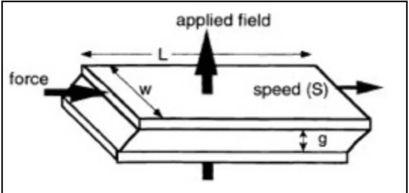
There is three working mode of MRF operations depending on the type of deformation employed: shear mode, flow mode or squeeze mode. Here we adopt shear mode shown in Fig. 2.1
In shear mode, the total force can be separated into a viscous (pure rheological) component Fr and a magnetic field dependent (magneto-rheological) component FS.
Fs =τ0(H )sgn(γ )Lw = τ 0(H )sgn(S)Lw
Fr =
µSLw g
We could used above two equation established the minimum volume of active fluid.
V = Lwg = µ τ0 2 ⎡ ⎣ ⎢ ⎤ ⎦ ⎥ × Fr FS ⎡ ⎣ ⎢ ⎤ ⎦ ⎥ × FS × S
2.2 Effect of MQL
The basic assumption regarding the fluid flow are (1) It is incompressible Newtonian fluid (2) The fluid motion is a flow with average velocity relative to the shaft.
In the case of incompressible flow through the bore of tool shaft, the nature of the flow is determined by the value of the Reynolds number.
where ρf is the density of the fluid, U is the average flow velocity, D is the internal diameter of shaft of the fluid, and µ is the viscosity of the fluid. The flow is laminar when
Re≤ 2300 .
Because the Reynolds number is small, the fluid flow is laminar ( Chapter 4 ) . Since the shaft is of small displacement, we assume that fluid flow in a shaft is similar to the flow in a tube. The velocity can be obtained by knowing fluid quantity fq and the cross-sectional of
fluid flow Af :
U= fq Af
Due to the incompressibility of fluid, the high pressure gas will reduced the sectional of fluid when applying MQL. If the volume ratio of gas to fluid is t ,the
cross-sectional of the fluid flow is
Af =
π D2
4(1+ t)
2.3 Equation of Motion Without Damper
In the chapter, we drive the equation of motions of BTA drill shafts, containing flowing fluid and subjected to a axial compressive force. The equation of motions of the BTA drill shaft is based on Euler-Bernoulli beam model.
The basic assumptions for the shafts in deriving the governing equations are as follow: (1) The drill shaft has a uniform cross section along its length L . (2) The plane section is
are ignored, i.e., stresses through the thickness of the shaft are ignored. (3) The drill shaft is balanced, i.e., at every cross section, the mass center coincides with the geometric center. (4) Axial deformations due to axial compressive force applied at the ends are ignored. (5) The fluid-flow velocity is constants in axial direction.(6)The drill shaft is assumed to be isotropic and homogeneous.
The system to be dealt with is shown in Fig 2.2. The differential equations of motion of the dill shaft can be derived by applying Hamilton’s principle, given by:
δ (T − V + W )dt
t 2 t1
∫
= 0 (2.1) where T and V are the kinetic and potential energies and δW is the virtual work done by the axial compressive force. All of the quantities are specified on the moving co-ordinate system in subsequent discussion.The kinetic energy of the drill shaft due to transverse and flowing fluid could be express as: T = 1 2 0 (ρ L
∫
Au22 +ρfAfu 2 + 2ρ fAfUuu′+ρfAfU 2 )dx (2.2)where ρ is the mass density of drill tube, A is the cross-sectional area of the drill tube, ρf is the density mass of fluid, Af is the cross-sectional of fluid flow, u is the lateral
displacement , the primes and overdots denote partial derivatives with respect to x ant time t .
The potential energy of the drill shaft due to bending and shear is expressed as:
V = 1 2 EIu′ 2 2 0 L
∫
dx (2.3)where E is Young’s modulus of the drill tube, I is transverse moment of inertia of a
cross-section of the drill.
Since axial compressive force for a Euler-Bernoulli beam is ignored:
W = 0 (2.4)
Applying Hamilton’s principe, the equations of motion for a rotating drill shaft containing flowing fluid and subject to a axial compressive force in a moving co-ordinate system can obtained as:
u+ 2ρfAfU ρA + ρfAf ′ u + ρfAfU 2 ρA + ρfAf ′′ u + EI ρA + ρfAf ′′′′ u = 0 (2.5)
If the flowing fluid is ignored for a non-rotating drill shaft, it is the same as the equations in [26]. This equations indicate that transverse motion is damped by the velocity of the fluid.
2.4 Simplified Equation of Motion With Damper
The equation of BTA drill shaft damped by a damper with damping constant c at
x=αLcan obtained as:
u+ 2ρfAfU ρA + ρfAf ′ u + ρfAfU 2 ρA + ρfAf ′′ u + EI ρA + ρfAf ′′′′ u + c ρA + ρfAf uδ(x − αL) = 0 (2.6)
where δ(x) denotes the Dirac function
The Eq(2.6) can be nondimensionalized by the following dimensionless parameters:
x = x L
U= UL(ρfAf EI ) 1/2 ρf = ρfAf ρA + ρfAf c = c L [EI(ρA + ρfAf)] 1/2 = c (ρA + ρfAf)Lω ω2 = EI (ρA + ρfAf)L 4
where ω denotes the eigenfrequency of the undamped beam without fluid. which takes the following form:
u+ 2Uρf
1/2′
u + U2u′′+ ′′′′u + c uδ(x−α) = 0 (2.7) we set following parameters:
k1= 2Uρf 1/2 k2 = U 2 we get u+ k1u′+ k2u′′+ ′′′′u + c uδ(x −α) = 0 (2.8)
The corresponding boundary conditions for both clamped ends are:
Fig. 2.1 Shear mode of MRF
Chapter 3 Method of Solution
3.1 Eigenvalues of the Equation of Motion
An approximate series solution of the differential equation (2.6) from Galerkin’s Method can be used in the form
u(x,t)≈ ur(x )ηr(t) r=1
n
∑
(3.1) where ur(x ) are the orthogonal eigenfunctions or mode shape functions of the no fluidcontained Euler-Bernoulli beam with the same boundary conditions of the system and ηr(t)
are the time dependent generalized coordinates.
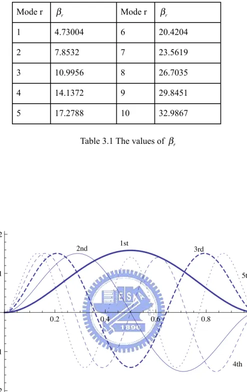
The eigenfunctions ur(x) are found to be
ur(x )= cosh(βrx )− cos(βrx )−σr[sinh(βrx )− sin(βrx )] (3.2)
with
σr =
coshβr − cosβr
sinhβr − sinβr (3.3)
where βrare the solution of
cosh(βr)cos(βr)= 1 (3.4)
The values of βr can not expressed as exact forms and we can compute these values
Substituting equation (3.1) into equation (2.8) and both sides of the equation are
multiplied by the sth eigenfunction us(x) and integrated from 0 to 1.By using the
orthogonality property of the eigenfunctions, the following set of ordinary differential
equations for the ηs(t) is obtained
arsηr+ k1brsηr + k2crsηr+ drsηr + cus(α) ur(α) r=1
n
∑
ηr = 0 (3.5)The elements of matrices ars,brs, crs, drsare:
ars = 0 r ≠ s 1 r = s ⎧ ⎨ ⎩ brs = 4βr 2β2 s βr 4 −β s 4{(−1) n+ m− 1} r ≠ s 0 r = s ⎧ ⎨ ⎪ ⎩⎪ crs = 4βr 2β2 s βr 4 −β s 4 (βrσr−βmσm){(−1) n+ m− 1} r ≠ s −βrσr r = s ⎧ ⎨ ⎪ ⎩⎪ drs = 0 r ≠ s βr 4 r = s ⎧ ⎨ ⎩
We can obtain the following form
Arsηr + Brsηr + Crsηr = 0 (3.6)
where Ars = ars
Crs = k2crs + drs If we let Q= ηr ηr ⎧ ⎨ ⎩ ⎫ ⎬ ⎭ P= 0 I −A−1C −A−1B ⎛ ⎝ ⎜ ⎞ ⎠ ⎟ or the form of Q= PQ (3.7)
It is an eigenvalue problem and by letting
Q(t)= Qeλt (3.8) and substituting it into Eq (3.7) we have
PQ=λQ (3.9)
We can solve the eigenvalues of the matrix P ,and find 2r eigenvalues λj which are
complex numbers composed of real parts and image parts. Note that the image parts are equal to the dimensionless eigenfrequencies of the tool shaft system.
The modal natural frequency ωi, modal damping ratio ζi can be defined as following:
ωi = (λjλj+1) 1/2 (3.10) ζi = − λj +λj+1 2ωi (3.11)
3.2 Sensitivities of Eigenvalues
To obtained the effect of damping coeffcient and position of damper , neglect the flowing fluid factor. In reference, the sensitivity of eigenvalues of a viscously damped clamped-free Bernolli-Euler beam was investigated. Thus the sensitivity of eigenvalues with respect to the changes in the magnitude of the damping constat and location of the damper attachment point can be obtained.[60]
Thus the system of equation of damped shaft without fluid from equation (3.5) is:
arsηr + drsηr+ cus(α) ur(α) r=1
n
∑
ηr = 0 (3.12)If the solution of the form ηs(t)=ηse
λt
and substituting it into (3.12), the following set of equations are obtained: [(λ2 I+ Ω) +λca(α)aT(α)]η = 0 (3.13) where η = [η1,...,ηn] T a(x )= [u1(x ),...,u2(x )] T Ω = diag(β4 ) then det[(λ2 I + Ω) +λca(α)aT(α)] = 0 (3.14)
By using the formula : det(Α + ΒppT
)= det A{1+ ΒpTΑ−1p} we can find the following correspondences
Α =λ2
I+ Ω , p = a(α) , Β = cλ
Hence the characteristic equation (3.14) can be reformulated as
1+ cλ ur 2(α) λ2 +β4 r = 0 r=1 n
∑
Then we can begin with the sensitivity of the eigenvalues with respect to the viscous damping constant c . ∂λ ∂c = ′λ = −λ c 1+ 2λ3c ur 2(α) (λ2 +β4 r) ^ 2 r=1 n
∑
⎡ ⎣ ⎢ ⎤ ⎦ ⎥ (3.13)Hence, it give an approximate formula for the eigenvalue λ(c) if the damping constant of the damper is changed by a small amount Δc
λ(c + Δc) ≈ λ(c) + ′λ Δc (3.14) By the similar operation [60]
∂λ ∂α = − ur(α)ur′(α) λ2 +β4 r r=1 n
∑
⎧ ⎨ ⎪ ⎩⎪ ⎫ ⎬ ⎪ ⎭⎪ ur 2(α) λ2+β4 r − 2λ ur 2(α) λ2+β4 r(
)
2 r=1 n∑
r=1 n∑
⎛ ⎝ ⎜ ⎜ ⎞ ⎠ ⎟ ⎟ (3.15)where u′(α) = βr r
[
sinh(βrα) + sin(βrα) − σr[cosh(βrα) − cos(βrα)]]
λ(α + Δα) ≈ λ(α) + ∂λ
Mode r βr Mode r βr 1 4.73004 6 20.4204 2 7.8532 7 23.5619 3 10.9956 8 26.7035 4 14.1372 9 29.8451 5 17.2788 10 32.9867
Table 3.1 The values of βr
1st 2nd 3rd 4th 5th 0.2 0.4 0.6 0.8 1.0 !2 !1 1 2
Chapter 4 Simulation
In order to solve the eigenvalue problem of BTA shaft, the following values from Catalog are used to examine the forgoing theoretical analysis:
Tube Length:L= 1.6m
Tube internal diameter:11.5mm
Tube external diameter:17.0mm
Cross-sectional area of the shaft: A= 1.231× 10⁻⁴m2
Cross-sectional area of the fluid:Af = 1.039 × 10
−4m2
Tube density:ρ = 7860kg / m3
Fluid density:ρf = 871kg / m3
Absolute viscosity: µ = 0.383kg / m ⋅sec Fluid quantity : fq = 60l / min
Young’s Modulus:E = 2.06 × 10¹¹
Pa Moment of inertia:I = 3.214 × 10⁻⁹
m2
Catalog recommends the fluid quantity fq = 50 ~ 100l / min .When fluid quantity
fq = 60l / min we have
U= fq Af
= 60l / min
Re= ρfUD
µ =
866× 9.625 × 0.023
0.383 = 500.6
We obtain that the fluid flow is laminar, and assumption in Chapter 2.2 is correct.
4.1 Calculate the Eigenvalue Problem
Table 4.1 shows the undamped natural frequencies of the tool shaft without fluid c= 0 ,
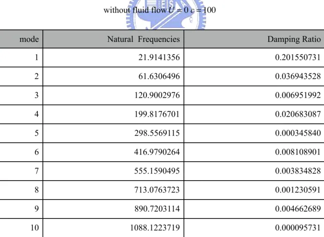
U= 0 . In order to figure out the damped natural frequencies and damping ratio effected by
fluid and damper, Table 4.2 is the natural frequencies and damping ratio of damped shaft without fluid when damper placed at 0.6L , c= 100N / (m / s) ,U = 0 . The natural frequencies
and damping ratio decrease as the damping coefficient increases. But the effect of damper on mode 1, mode 4, mode 6, mode 7, mode 9 are more obvious due to the displacement of damper.
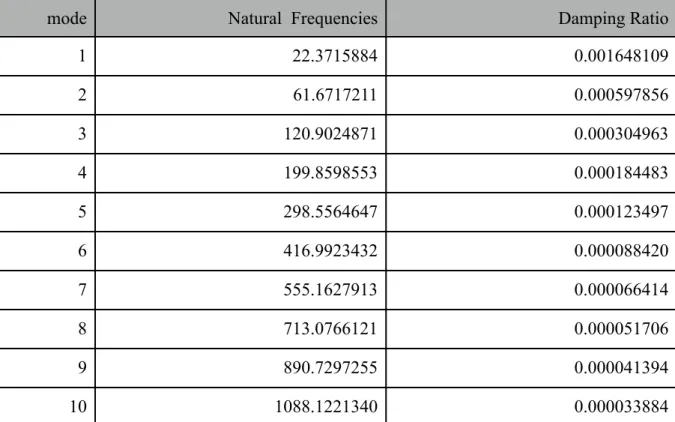
Table 4.3 is the natural frequencies and damping ratio shaft without damper with fluid
U= 9.625m / sec ,c = 0 . The natural frequencies and damping ratio decrease as the flow velocity increases. Compared the effect between damper and fluid flow that damper causes more change of frequencies and damping ratio. But the influence of damper is dependent on the damper location.
Finally Table 4.4 shows the damped natural frequencies and damping ratio of the tool shaft with fluid when damper placed at 0.6L , c= 100N / (m / s) ,U = 9.625m / sec .
Table 4.1 Undamped natural frequencies of the tool shaft without fluid flow U = 0 c = 0
mode Natural Frequencies
1 22.3732784 2 61.6727502 3 120.9032193 4 199.8604238 5 298.5569294 6 416.9927361 7 555.1631316 8 713.0769122 9 890.7299940 10 1088.1223768
Table 4.2 Damped Natural Frequencies and damping ratio of the Tool Shaft without fluid flow U= 0 c = 100
mode Natural Frequencies Damping Ratio
1 21.9141356 0.201550731 2 61.6306496 0.036943528 3 120.9002976 0.006951992 4 199.8176701 0.020683087 5 298.5569115 0.000345840 6 416.9790264 0.008108901 7 555.1590495 0.003834828 8 713.0763723 0.001230591 9 890.7203114 0.004662689 10 1088.1223719 0.000095731
Table 4.3 Natural Frequencies and damping ratio of the shaft without damper with fluid flow U = 9.625m / sec , c = 0
mode Natural Frequencies Damping Ratio
1 22.3715884 0.001648109 2 61.6717211 0.000597856 3 120.9024871 0.000304963 4 199.8598553 0.000184483 5 298.5564647 0.000123497 6 416.9923432 0.000088420 7 555.1627913 0.000066414 8 713.0766121 0.000051706 9 890.7297255 0.000041394 10 1088.1221340 0.000033884
Table 4.4 Damped Natural Frequencies and damping ratio of the tool shaft with fluid when damper placed at 0.6L , c= 100N / (m / s) ,U = 9.625m / sec
mode Natural Frequencies Damping Ratio
1 21.9048214 0.203213791 2 61.6282566 0.037541995 3 120.8993091 0.007256998 4 199.8163386 0.020867630 5 298.5564341 0.000469338 6 416.9783345 0.008197329 7 555.1585678 0.003901245 8 713.0760268 0.001282298 9 890.7198710 0.004704084 10 1088.1221255 0.000129616
4.2 Sensitivity of the Eigenvalues of the Shaft with Damper
Table 4.5 gives an indication on the accuracy of the sensitivity related equation (3.14) Small changes of the damping constant c= 100N / (m / s) are taken as Δc = 1,5,10
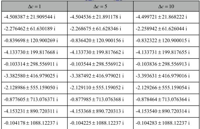
respectively. Similarly Table 4.6 gives an indication on the accuracy of the sensitivity-based formula (3.16) . Small changes in the location of the damper attachment point are taken as
Δα = 0.0005,0.001,0.005 .
Table 4.5 Eigenvalues due to the change of the damping constant c byΔc
Δc = 1 Δc = 5 Δc = 10 -4.508387± 21.909544 i -4.504536± 21.891178 i -4.499721± 21.868222 i -2.276462± 61.630189 i -2.268675± 61.628346 i -2.258942± 61.626044 i -0.839698± 120.900269 i -0.836420± 120.900156 i -0.832322± 120.900015 i -4.133730± 199.817668 i -4.133730± 199.817662 i -4.133731± 199.817655 i -0.103314± 298.556911 i -0.103544± 298.556912 i -0.103836± 298.556913 i -3.382580± 416.979025 i -3.387492± 416.979021 i -3.393631± 416.979016 i -2.128986± 555.159050 i -2.129110± 555.159052 i -2.129266± 555.159054 i -0.877605± 713.076371 i -0.877985± 713.076368 i -0.878464± 713.076364 i -4.153231± 890.720311 i -4.153368± 890.720313 i -4.153540± 890.720314 i -0.104178± 1088.12237 i -0.104225± 1088.12237 i -0.104283± 1088.12237 i
Table 4.6 Eigenvalues due to the change of the damper attachment point α by Δα Δα = 0.0005 Δα = 0.001 Δα = 0.005 -4.501316± 21.915787 i -4.493253± 21.917441 i -4.27734± 21.930771 i -2.296618± 61.629973 i -2.314835± 61.629292 i -2.460658± 61.623642 i -0.821902± 120.900425 i -0.803443± 120.900549 i -0.661704± 120.901408 i -4.142648± 199.817485 i -4.151160± 199.817308 i -4.20441± 199.816195 i -0.114861± 298.556907 i -0.127070± 298.556902 i -0.245863± 298.556828 i -3.345933± 416.979312 i -3.310006± 416.979598 i -3.006178± 416.981899 i -2.179115± 555.158854 i -2.229248± 555.158655 i -2.625986± 555.156920 i -0.831969± 713.076426 i -0.787356± 713.076477 i -0.467411±713.076759 i -4.171926± 890.720223 i -4.188836± 890.720144 i -4.257137± 890.719820 i -0.126961± 1088.122369i -0.151934± 1088.12236 i -0.426376± 1088.12229 i
4.3 Shaft Behavior Effected by Placement of Damper
The vibration of any modes can be controlled by changing the damper attachement point. Seeing mode shape (Fig. 3.1), the damper position can be selected to control the natural frequency and damping ratio of any modes. In order to obtain the effect, the damper placed at
0.3L , 0.5L , 0.8L is chosen to control the mode 2, mode 1 and mode 3.
Table 4.7 and Table 4.10 shows the natural frequency and damping ratio controlled of each modes at different damper placement. The smaller natural frequency and larger damping ratio of mode 1 is at 0.5L , mode 2 at 0.3L , mode 3 at 0.8L . The results is exactly the same
Table 4.7 Natural frequency due to placement of damper Mode 0.3L 0.5L 0.8L 1 2 3 4 5 22.22667439 21.71949620 22.3583680 61.48373026 61.67275024 61.5947930 120.89254994 120.82996362 120.8631327 199.86006195 199.86042384 199.8260821 298.53250491 298.52654171 298.5553666
Table 4.8 Damping ratio due to placement of damper
Mode 0.3L 0.5L 0.8L 1 2 3 4 5 0.114290593 0.239977559 0.03650243 0.078328539 0 0.05026455 0.013284855 0.034805757 0.04002990 0.001902990 0 0.01853719 0.127910337 0.014267223 0.00323560
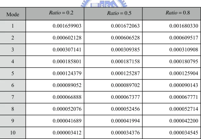
4.4 Shaft Behavior Effected by MQL Applying
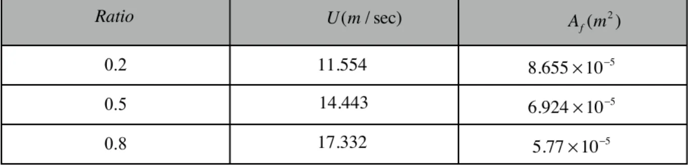
Finally, Table 4.9 and Table 4.10 compare the natural frequency and damping ratio when MQL applying under the ratio of gas to fluid is 0.2, 0.5 and 0.8. The flow velocity U
and cross-section area of fluid Af are listed in Table 4.11. The results show the natural
Table 4.9 Natural frequency due to the ratio of gas to fluid
Mode Ratio= 0.2 Ratio= 0.5 Ratio= 0.8
1 2 3 4 5 6 7 8 9 10 22.371255 22.370756 22.370258 61.671516 61.671211 61.670905 120.902341 120.902123 120.901905 199.859742 199.859572 199.859402 298.556372 298.556233 298.556094 416.992264 416.992147 416.992029 555.162723 555.162621 555.162519 713.076552 713.076462 713.076372 890.729671 890.729591 890.729511 1088.122085 1088.122012 1088.121940
Table 4.10 Damping ratio due to the ratio of gas to fluid
Mode Ratio= 0.2 Ratio= 0.5 Ratio= 0.8
1 2 3 4 5 6 7 8 9 10 0.001659903 0.001672063 0.001680330 0.000602128 0.000606528 0.000609517 0.000307141 0.000309385 0.000310908 0.000185801 0.000187158 0.000180795 0.000124379 0.000125287 0.000125904 0.000089052 0.000089702 0.000090143 0.000066888 0.000067377 0.000067771 0.000052076 0.000052456 0.000052714 0.000041689 0.000041994 0.000042200 0.000003412 0.000034376 0.000034545
Table 4.11 Flow velocity U and cross-section area of fluid due to the ratio of gas to fluid
Ratio U(m / sec) Af(m2
)
0.2 11.554 8.655× 10⁻⁵
0.5 14.443 6.924× 10⁻⁵
Chapter 5 Conclusions
This study deals with the eigenvalues of a damped BTA drill shaft with fluid-flow. The boundary conditions of the beam is assumed clamped-clamped. Also the sensitivity formulas with respect to changes in the magnitude of the damping constan and location of the damper attachment point have been established.
By doing research on eigenvalues and sensitivity, it is helpful when engineers design a changeable damping system like MR damper or optimize design about the damper location and damping coefficient. Finally, this study has established a simple formula about the influence of natural frequency and damping ratio of BTA shaft when applying MQL.
References
[1] Rudd. P. and Hetherington, I., “ Advances in Precision Holemaking,” Manufacuring Engineering, Vol. 102, No. 6, June 1989, pp, 87-89
[2] F. Klocke, G. Eisenblätter, Dry cutting, Ann. CIRP 46 (2) (1997) 519–526.
[3] F. Klocke, A. Schulz, K. Gerschwiler, et al., Saubere Fertigungstechnologien—Ein Wettbewerbsvorteil von morgen in: Wettbewerbsfaktor Produktionstechnik—Aachener Perspektiven, Aachener Werkzeugmaschinen-Kolloquium (AWK), VDI-Verlag, Düsseldorf, 1996.
[4] D. Dudzinski, A. Devillez, A. Moufki, D. Larrouque` re, V. Zerrouki, J. Vigneau, A review of developments towards dry and high speed machining of Inconel 718 alloy, International Journal of Machine Tools & Manufacture 44 (4) (2004) 439–456.
[5] K. Weinert, I. Inasaki, J.W. Sutherland, T. Wakabayashi, Dry machining and minimum quantity lubrication, Annals of the CIRP 53 (2) (2004) 511–538.
[6] K. Weinert, I. Inasaki, J.W. Sutherland, T. Wakabayashi, Dry machining and minimum quantity lubrication, Ann. CIRP 53 (2) (2004) 511–537.
[7] G. Byrne, D. Dornfeld, B. Denkena, Advancing cutting technology, Ann. CIRP 52 (2) (2003) 483–507.
[8] K. Weinert, Trockenbearbeitung und Minimalmengenkuehlschmierung, Springer, Berlin, 1999.
[9] F. Klocke, K. Gerschwiler, Trockenbearbeitung—Grundlagen, Grenzen, Perspektiven, in: VDI-Berichte, 1240 (1996), 1–43.
[10] Winslow, W. M., 1949, “Induced vibration of suspensions,” Journal of Applied Physics 20(12), 1137–1140.
[11] Carlson, J. D., 1999, “Magnetorheological fluid actuators,” Adaptronics and Smart Structures, H. Janocha, editor, Springer-Verlag, Berlin, pp. 180–195.
[12] J. Rabinow: The Magnetic Fluid Clutch, AIEE Transactions 67, pp. 1308—1315, 1948 [13] Sakuma, K., Taguchi,K. and Katsuki, A., “Study on Deep-Hole Boring by BTA System Solid Boring Tool --- Behavior of Tool and its Effects on Profiles of Machined Hole”, 14, 3, pp. 143-148, Bulletin of the Japan Sociery of Precision Engineering,1980.
[14] Chandrashekhar, S., Osman, M. O. M. and Sankar, T. S.,”An Analytical Time Domain Evaluation of the cutting Forces in BTA Deep Hole Machining using the Thin Shear Plane Model”, 22, 4, pp. 697-721, International Journal of Production Research, 1984.
[14b] Chandrashekhar, S., Osman, M. O. M. and Sankar, T. S.,”An Experimental Investigation for the Stochastic Modelling of the Resultant Force System in BTA Deep Hole Machining”, 23, 4, pp. 657-673, International Journal of Production Research, 1985.
[15] Chandrashekhar, S., Osman, M. O. M. and Sankar, T. S.,”A Stochastic Characterization of the Machine Tool Workpiece System in BTA Hole Machining--Part I: Mathematical Modelling and Analysis”, 2, 1&2, pp.37-69, Advanced Manufacturing Process, 1987.
[16] Blevins, R. D., Flow-Induced Vibration. Krieger Publishing Company, 1986, See Chapter 10.
[17] Newland, D. E., Mechanical Vibration Analysis and Computation, John Wiley & Sons, Inc., New York, 1989.
[18] Yumshtyk, M. G. and Kedrov, S. S., “Gun Drill Vibration in Deep Drill”,39, 5, pp. 34-36, Machines and Tooling, 1968.
[19] Kirrillin, B. N., “Vibratory Drilling with Gun Drills”, 39, 5, pp. 30-32, Machines and Tooling, 1968.
[20] Lundgren, T. S., Sethna, P. R. and Bajaj, A. K., “Stability Boundaries for Flow Induced Motions of Tubes with an Inclined Terminal Nozzle”, Journal of Sound and Vibration, Vol. 64, No. 4, 1979, pp.553-571
[21] Edelstein, W. S., Chen, S. S. and Jendrzejczyk, J. A., “A Finite Element Computation of the Flow-Induced Oscillations in a Cantilevered Tube”, Journal of Sound and Vibration, Vol. 107, No. 1, 1986, pp.121-129
[22] Paidoussis, M. P. and Issid, N. T., “Dynamic Stability of Pipes Conveying Fluid”, Journal of Sound and Vibration, Vol. 33., No. 3, 1974, pp. 267-294
[23] Paidoussis, M. P., “Dynamics of Tubular Cantilevers Conveying Fluid”, Journal Mechanical Engineering Science, Vol. 12., No. 2, 1970, pp. 85-103.
[24] Yoshizawa, M., Nao, H., Hasegawa, E. and Tsujioka, Y., “Buckling and postbuckling behavior of a flexible pipe conveying fluid”, 28, pp. 1218-1225, Bulletin of the JSME, 1985. [25] Thompson, J. M. T. and Lunn, T. S., “Static Elastic Formulations of a Pipe Conveying Fluid”, Journal of Sound And Vibration, Vol. 77.,No. 1, 1981, pp.127-132
[26] Chin, J. H. and Lee, L. W., “A Study on the Tool Eigenproperties of a BTA Deep Hole Drill - Theory and Experiments”, 35, 1, pp. 29-49, International Journal of Machine Tools & Manufacture, Research and Application, 1995.
[28] Hill, J. L. and Swanson, C. P., “Effects of Lumped Masses on the Stability of Fluid Conveying Tubes”, pp. 494-497, ASME Journal of Applied Mechanics, 1970.
[29] Sugiyama, Y., Kawagoe, H., Kishi, T. and Nishiyama, S., “Studies on the Stability of Pipes Conveying Fluid (The Combined Effect of a Spring Support and a Lumped Mass)”, 31, 1, pp. 20-26, JSME International Journal Series 1, 1988.
[30] Chin, J. H., Hsieh, C.T. and Lee, L. W., “The Shaft Behavior of BTA Deep Hole Drilling Tool”, 38, 5, pp. 461-482, International Journal of Mechanical Sciences, 1996.
[31] Eshleman, R. L. and Eubanks, R. A., “On the Critical Speeds of a Continuous Shaft-Disk System”, Transactions of the ASME, Journal of Engineering for Industry, November 1967, pp. 645-652
[32] Eshleman, R. L. and Eubanks, R. A., “On the Critical Speeds of a Continuous Rotor”, Transactions of the ASME, Journal of Engineering for Industry, November 1969, pp. 1180-1188.
[33] Lee, C. W., Katz, R., Ulsoy, A. G. and Scott, R. A., “ Modal Analysis of a Distributed Parameter Rotating Shaft”, 122, 1, pp. 119-130, Journal of Sound and Vibration, 1988.
[35] Katz, R., Lee, C. W., Ulsoy, A. G., and Scott, R. A., “Modal Analysis of a Distributed Parameter Rotating Shaft”, Journal of Sound and Vibration, Vol. 122, No. 1,1988, pp.119-130 [38] Han, R.P.S. and Zu, J. W. Z., ”Modal Analysis of Rotating Shafts: A BodyFixed Axis Formulation Approach”, 156, 1, pp. 1-16, Journal of Sound and Vibration, 1992.
[39] Zu, J. W. Z. and Han, R. P. S., “Dynamic Response of a Spinning Timoshenko Beam with General Boundary Conditions and Subjected to a Moving Load”, 61, pp.152-160, ASME Journal of Applied Mechanics, 1994.
[42] Edelstein, W. S. and Chen, S. S., “Flow-Induced Instability of an Elastic Tube with a Variable Support”, 84, pp.1-11 Nuclear Engineering Design, 1985
[43] K. Weinert, Trockenbearbeitung und Minimalmengenkuehlschmierung, Springer, Berlin, 1999
[44] R. Heinemann, Improving the Performance of Small Diameter Twist Drills in Deep-Hole Drilling, PhD-Thesis, UMIST, 2004
[45] G. Barrow, Wear of cutting tools, Tribology 1 (1972) 22–30.
[46] D.M. Haan, S.A. Batzer, W.W. Olson, J.W. Sutherland, An experimental study of cutting fluid effects in drilling, Journal of Materials Processing Technology 71 (2) (1997) 305–313
[47] W. Rehbein, Bohren in hochlegierten Stahl mit Minimalmengenkuehlschmierung, Tribologie und Schmierungstechnik 46 (4) (1999) 5–10
[48] H.A. Kishawy, M. Dumitrescu, E.G. Ng, M.A. Elbestawi, Effect of coolant strategy on tool performance, chip morphology and surface quality during high-speed machining of A356 aluminum alloy, International Journal of Machine Tools & Manufacture 45 (2) (2005) 219– 227
[49] M. Rahman, A.S. Kumar, M.U. Salam, Experimental evaluation on the effect of minimal quantities of lubricant in milling, International Journal of Machine Tools & Manufacture 42 (5) (2002) 539–547
[50] E. Brinksmeier, A. Walter, R. Janssen, P. Diesen, Aspects of cooling lubrication reduction in machining advanced materials, Journal of Engineering Manufacture, Proceedings of the Institution of Mechanical Engineers, London (Part B) 213 (1999) 769–778
[51] H. Hanyu, S. Kamiya, Y. Murakami, M. Saka, Dry and semi-dry machining using finely crystallized diamond coating cutting tools, Surface and Coatings Technology 173–174 (2003) 992–995.
[52] A.R. Machado, J. Wallbank, The effect of extremely low lubricant volumes in machining, Wear 210 (1–2) (1997) 76–82.
[53] T. Wakabayashi, H. Sato, I. Inasaki, Turning using extremely small amounts of cutting fluids, JSME International Journal, Series C 41 (1) (1998) 143–148.
[54] J.L. Nikolajsen, M.S. Hoque, An electro-viscous damper, Proceeding of Workshop on Rotor-dynamic Problems in High-Performance Turbo-Machinery, Texas, USA, NASA CP-3026, 1988, pp. 65–73.
[55] J.L. Nikolajsen, M.S. Hoque, An electro-viscous damper for rotor application, Journal of Vibration and Acoustics 112 (1990) 440–443.
[56] J.M. Vance, D. Ying, Experimental measurements of actively controlled bearing damping with an electrorheological fluid, Journal of Engineering for Gas Turbines and Power 122 (2000) 337–344.
[57] Wang, J. and Meng, G., 2003, “Experimental study on stability of an MR fluid damper– rotor–journal bearingsystem,” Journal of Sound and Vibration 262, 999–1007.
[58] C.S. Zhu, Dynamics of a rotor supported on magnet magnetorheological fluid squeeze film damper, Chinese Journal of Aeronautics 14 (2001) 6–12.
[59] Forte, P., Paterno, M., and Rustighi, E., 2002, “A magnetorheological fluid damper for rotor applications,” in Proceedings of the 6th International Conference on Rotor Dynamics, IFToMM, Sydney, Australia, September30–October 4, pp. 63–70.
[60] M. Gurgoze,1998, “On the sensitivities of the eigenvalues of a viscously damped cantilever carrying a tip mass” Journal of Sound and Vibration 216,2,215-225