國
立
交
通
大
學
電子工程學系 電子研究所碩士班
碩
士
論
文
適用於分散式暫存記憶體多核心平台之多媒體多解
析處理應用最佳化
Optimizing Multi-Resolution Applications on
Distributed Scratchpad Memory Multicore Architecture
研究生: 甘禮源
指導教授: 劉志尉
適用於分散式暫存記憶體多核心平台多媒體之多解析處理
應用最佳化
Optimizing Multi-Resolution Applications on Distributed
Scratchpad Memory Multicore Architecture
研 究 生:甘禮源
Student: Li-Yuan Kan指導教授:劉志尉 博士
Advisor: Dr. Chih-Wei Liu國 立 交 通 大 學
電子工程學系 電子研究所班
碩士論文
A Thesis
Submitted to Department of Electronics Engineering & Institute of Electronics College of Electrical and Computer Engineering
National Chiao Tung University
In partial Fulfillment of the Requirements for the Degree of Master of Science
in
Electronics Engineering August 2011
Hsinchu, Taiwan, Republic of China
適用於分散式暫存記憶體多核心平台之多媒體多解
析處理應用最佳化
研究生:甘禮源
指導教授:劉志尉 博士
國立交通大學
電子工程學系 電子研究所
摘要
相較於使用快取記憶體的多核心架構,分散式暫存記憶體多核心平台可以達到功率效率 的特性,適用於可攜式電子產品等嵌入式系統中。但是要利用分散式暫存記憶體多核心 平台去加速運算,軟體程式的撰寫卻非常困難,不但花費時間而且容易出錯。分散式暫 存記憶體多核心平台為程式撰寫帶來許多挑戰,包含核心間同步、工作負載平衡,甚至 包括資料的讀取上都考驗程式設計者。在這篇論文中,我們針對多媒體多解析的應用去 做分析和探討,希望可以在分散式暫存記憶體多核心平台有效率地去利用硬體資源。多 解析處理應用常見於多媒體應用中,像是影像處理、訊號處理及智慧型多媒體處理。它 會針對於不同解析度進行反覆的運算處理、蘊含豐富的資料區域性,需要頻繁的資料傳 輸去完成運算。在分散式暫存記憶體多核心平台實現此種應用時,常因為資料傳輸的問 題,導致效能上無法達到線性的加速。因此本論文提出一個基於『資料區域性』為主軸 的切割方式,透過妥善利用不同解析度間之資料區域性及有效率的暫存記憶體使用來減 少不必要的資料讀取;藉此方式達到降低核心間資料網絡的負擔,也避免發生記憶體資 源的競爭。本研究以物體辨識當作一個例子,利用 Cell 多核心處理器做為我們的實驗平 台;所提出的方法可以減少 95%的資料傳輸且達到 35.1%的效能提升,並且在六顆處理 器的平行處理下,相較於 CellCV 版本在一顆處理器上的處理時間,可以達到 5.6 的增 益。Optimizing Multi-Resolution Application on
Distributed Scratchpad Memory Multicore
Architecture
Student: Li-Yuan Kan Advisor: Dr. Chih-Wei Liu
Department of Electronics Engineering Institute of Electronics
National Chiao Tung University
ABSTRACT
Compared to cache-based multicore architecture, distributed scratchpad memory multicore architecture is more power efficient, which makes it suitable for embedded system. However, software programming for distributed scratchpad memory multicore is rather complicated and time-consuming. It brings new challenges including synchronization, workload balancing and even memory transfer. In this thesis, we focus on parallelization of multi-resolution applications on distributed scratchpad memory architecture. Multi-resolution application is used in variety domains like video compression, signal processing and intelligent multimedia. It contains multi-level data locality, repeated computations are performed on different resolutions. Abundant data transfers are demanded to complete the operation. Therefore, the memory transfer issue usually prevents multi-resolution application from getting linear acceleration on multicore. We propose a data-oriented task partition to achieve balanced workload and low-data-transfer by take advantage of inter-resolution locality. On Sony Playstation3, a typical distributed scratchpad memory multicore with 6 cores, object detection is parallelized using proposed data-oriented task partition. According to the experimental results, we obtain 5.6 times speedup from running on single core. 95% data transfer can be reduced and up to 35.1% performance improvement is obtained.
誌 謝
經過漫長的研究所生活,這幾年來受到許多人幫助及鼓勵,最終才能完成碩士學業,在 此致上最深的感激。 感謝劉志尉教授,對我總是充滿耐心以及鼓勵,使我在專業知識及研究態度上受益良 多。特別感謝賴尚宏教授、陳添福教授及賴伯承教授,謝謝你們在百忙之中,撥冗參與 論文口試,並對我的研究給予寶貴的意見,讓此篇論文更加完備充實。 特別感謝小 A 學長不管是在研究上或者生活上的照顧,給我很多幫助和信心,讓我可以 越挫越勇而不放棄,在研究路上可以堅持地走下去,在此特別的感謝。 感謝實驗室學長姐、同學及學弟們。感謝歐、阿圳、郭、強哥、電七、老闆、阿 Van、 阿德、李岳泰和 Hank,感謝學長們在研究生生涯中的各項協助及鼓勵。感謝安綺、阿 捲、阿賢、宗慶、哲偉、小鈺、晉毫、宗宜、志清和益權,謝謝學弟妹們在平時的一切 幫忙。 感謝小黑和雅婷,分享這一路的喜怒哀樂,讓我知道在這條路上,我並不是孤獨的,總 是可以在失敗時再站起來,繼續勇往直前。 感謝關心我的朋友,可是適時的聽我的傾訴,並且給我打氣與建議。 最後,感謝我最親愛的家人。爸、媽、大姐、二姐還有二姐夫,感謝你們一路上的支持 及鼓勵,沒有你們就沒有今日的我,謝謝你們。 謹將此篇論文獻給所有曾支持我、協助我的人,衷心的感謝並祝福你們。 禮源 謹誌於 新竹 201C
ONTENTS
1 INTRODUCTION ... 1
1.1 Distributed Scratchpad Memory Multicore ... 2
1.2 Multimedia applications ... 4
1.3 Porting multimedia applications on DSM multicore ... 5
1.4 Multi-resolution applications ... 11
1.5 Problem formulation and contributions ... 11
1.6 Thesis organization ... 12
2 MULTI-RESOLUTION APPLICATIONS ... 14
2.1 Object detection algorithm ... 15
2.2 Implementation on DSM multicore ... 21
2.3 CellCV simulation results ... 22
2.4 Task Reorder and Row-Based Splitting ... 25
2.5 Observation ... 28
3 DATA-ORIENTED TASK PARTITION ... 29
3.1 Data-oriented task partition ... 30
3.2 Tile-based Scanning ... 30
3.3 Difficulty and Overhead ... 32
3.4 3-Step Optimization Flow ... 34
3.5 Design results ... 39
4 EXPERIMENT RESULTS ... 41
4.1 Cell Architecture ... 42
4.2 Parameters settings and results ... 51
5 CONCLUSIONS ... 58
L
IST OF
F
IGURES
FIGURE 1-1ONE EXAMPLE OF DISTRIBUTED SCRATCHPAD MEMORY ARCHITECTURE ... 2
FIGURE 1-2SCRATCHPAD MEMORY ARRAY ... 3
FIGURE 1-3SCRATCHPAD MEMORY ORGANIZATION ... 3
FIGURE 1-4CACHE MEMORY ORGANIZATION ... 4
FIGURE 1-5EXAMPLE –JPEG ENCODER ... 5
FIGURE 1-6DEVELOPED DUAL-CORE SIMULATION PLATFORM ON COWARE ... 7
FIGURE 1-7OPTIMIZATION FLOW FOR EFFICIENTLY PARALLELIZING MULTIMEDIA APPLICATIONS ON MULTICORE .... 9
FIGURE 2-1HARR-LIKE BASED OBJECT DETECTION ... 16
FIGURE 2-2CASCADE CLASSIFIER ... 16
FIGURE 2-3INTEGRAL IMAGE ... 18
FIGURE 2-4SCALING WINDOW DETECTION ... 19
FIGURE 2-5DATA FLOW OF FEATURE MATCHING ... 21
FIGURE 2-6RESOLUTION-BASED TASK PARTITION ... 21
FIGURE 2-7DYNAMIC TASK SCHEDULING MECHANISM – CENTRALIZED TASK QUEUE ... 22
FIGURE 2-8SPEEDUP CURVE @2~6SPE ... 23
FIGURE 2-9WORKLOAD DISTRIBUTION ON [email protected] SCALING FACTOR AND 640×480 IMAGE ... 24
FIGURE 2-10WORKLOAD COMPARISON (NORMALIZED TO SINGLE CORE) ... 24
FIGURE 2-11TASK SEQUENCE USING 5-SPE IN CELLCV ... 25
FIGURE 2-12TASK ALLOCATION USING 5-SPE IN CELLCV... 26
FIGURE 2-13INTERLEAVED TASK REORDER ... 26
FIGURE 2-14 TASK ALLOCATION USING 6-SPE IN CELLCV ... 27
FIGURE 2-15ROW-BASED TASK SPLITTING ... 27
FIGURE 2-16TASK ALLOCATION USING ROW-BASED TASK SPLITTING ... 27
FIGURE 3-1DATA-ORIENTED TASK PARTITION DIFFERS FROM RESOLUTION-BASED PARTITION ... 30
FIGURE 3-2TILE-BASED SCANNING ... 31
FIGURE 3-3BOUNDARY ISSUE IN X-DIRECTION AND Y-DIRECTION ... 33
FIGURE 3-4 PLATFORM-DEPENDENT OPTIMIZATION FLOW ... 34
FIGURE 3-5APPLICATION-SPECIFIC ANALYSIS OF CLASSIFIER ... 35
FIGURE 3-6HARDWARE-DEPENDENT ANALYSIS OF CLASSIFIER ... 36
FIGURE 3-7TILE-SHAPE ANALYSIS ... 37
FIGURE 3-8GRANULARITY ANALYSIS ... 38
FIGURE 3-9ACCESS COUNT COMPARISON ... 39
FIGURE 3-10TRANSFER SIZE COMPARISON ... 39
FIGURE 4-1BLOCK DIAGRAM OF CELL BROADBAND ENGINE ... 42
FIGURE 4-3PPEFUNCTIONAL UNITS ... 43
FIGURE 4-4SPEBLOCK DIAGRAM... 45
FIGURE 4-5SPEFUNCTIONAL UNITS ... 46
FIGURE 4-6ELEMENT INTERCONNECT BUS (EIB) ... 48
FIGURE 4-7VGA SET ... 51
FIGURE 4-8SCALED TEST SET ... 52
L
IST OF
T
ABLES
TABLE 2-1 PERFORMANCE OF ROW-BASED SPLITTING ... 20
TABLE 2-2 PERFORMANCE OF ROW-BASED SPLITTING ... 28
TABLE 3-1 STATIC ANALYSIS OF TILE-BASED SCANNING ... 32
TABLE 3-2 WORKLOAD BALANCE COMPARISON ... 40
TABLE 4-1 PERFORMANCE COMPARISON @VGA SET ... 52
TABLE 4-2 ACCELERATION OF CELLCV@VGA SET ... 53
TABLE 4-3 ACCELERATION OF ROW-BASED SPLITTING @VGA SET ... 54
TABLE 4-4 ACCELERATION OF DATA-ORIENTED TASK PARTITION @VGA SET ... 54
TABLE 4-5 PERFORMANCE IN FRAME RATE @VGA SET ... 54
TABLE 4-6 PERFORMANCE COMPARISON @ SCALED TEST SET ... 55
TABLE 4-7 ACCELERATION OF CELLCV@ SCALED TEST SET ... 55
TABLE 4-8 PERFORMANCE OF ROW-BASED SPLITTING @ SCALED TEST SET ... 56
TABLE 4-9 PERFORMANCE OF DATA-ORIENTED TASK PARTITION @ SCALED TEST SET ... 56
1 I
NTRODUCTION
Multimedia applications have become an important workload of computing system for consume electronic. And multi-resolution is one special case in multimedia application. Because of computation complexity and application requirement, single core is out of power to reach the performance constraint and additionally accompanying with dramatic increasing of power consumption, memory latency and circuit complexity. Most new processors architectures are branching into more cores rather than better cores. Multicore architectures have become the mainstream rather than the exception in computing landscape. The problem is how to exploit the parallelism and make full utilization of all cores to reach the expected performance gain with efficiency.
1.1 Distributed Scratchpad Memory Multicore
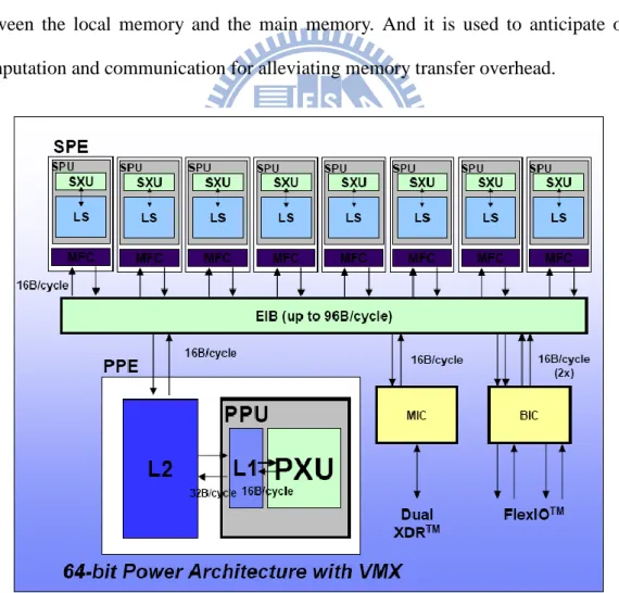
Distributed scratchpad memory multicore architecture becomes popular for parallel-accelerated computation. The architecture can be described as follows in Figure 1-1. Figure 1-1 is one typical example of distributed scratchpad memory, Cell processor. There are several cores in the system and each core is embedded with software-controlled local store memory. Direct memory access (DMA) usually participates memory transfer. Direct memory access (DMA) is a feature of modern computers and microprocessors that allows certain hardware subsystems within the computer to access system memory for reading and/or writing independently of the central processing unit. DMA is used for transferring data between the local memory and the main memory. And it is used to anticipate overlapping computation and communication for alleviating memory transfer overhead.
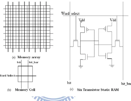
By [1], the hardware of scratchpad memory is shown like Figure 1-2. The scratchpad is a memory array with the decoding and the column circuit logic. The assumption here is that the scratchpad memory occupies one distinct part of the memory address space with the rest of the space occupied by main memory. Thus, we need not check for the availability of the data/instruction in the scratchpad. It reduces the comparator and the signal miss/hit acknowledging circuitry.
Figure 1-2 Scratchpad memory array
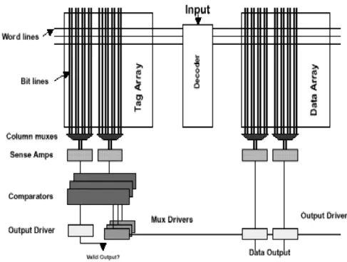
The 6 transistor static RAM construct a memory cell as shown in Figure 1-2 (c). The cell has one R/W port. Each cell has two bit-lines, bit and bit bar, and one word-line. The complete scratchpad memory is as shown in Figure 1-3. Comparing with cache memory, scratchpad memory has less hardware circuit. In Figure 1-4, cache memory has additional circuit of tag array and comparator circuit check for the availability of the data/instruction in the cache. From this paper, average reduction was 40% in time, power consumption and area. While application is considered, distributed scratchpad memory can support huge computing power but low power consumption.
Figure 1-4 Cache memory organization
Therefore, scratchpad memory organization is suitable for current embedded processors particularly in the area of multimedia applications and graphic controllers
1.2 Multimedia applications
system for consumer electronic. For example, audio standards are AAC, MP3, Dolby Digital (AC3), etc. And multimedia standards are M-JPEG, MPEG-1, 2, and 4, H.263, H.264, etc. Even 3-D graphic processing is more and more popular in the future entertainment. There are some data characteristics in multimedia application. (1) High computation complexity, it requires tens to hundreds of billions computation per second for modern multimedia applications. (2) Streaming process, application can be simply decomposed into stream and kernel. Continuously ordered set of data and the FIFO-communicated processes are expressed as the operations applied on stream processing. Lets take JEPG encode for a example in Figure 1-5. It can decomposes into four computation kernel as color space transform (CST), discrete cosine transform (DCT), quantization (Q) and variable length coding (VLC). (3) Predictable data movement, continuous input data imports into computing system and export after go through a cascade of computing kernel. Whereas the process behavior is regular like DCT starting after CST is finished, memory transfer can be pre-loaded for computing kernel. Because of above data characteristic, distributed scratchpad memory multicore is appropriate for multimedia application to elaborate high performance and power efficient via application considered.
Figure 1-5 Example – JPEG encoder
1.3 Porting multimedia applications on DSM multicore
programmer to parallelize multimedia applications on multicore efficiently. There are several factors we have to consider. The superior performance can only be obtained through a careful co-design and optimization crossing four critical design issue, including choosing appropriate parallelism level, balancing workload, reducing synchronization overhead and memory and interconnect bandwidth. In multicore programming, the programmer is now responsible to generate concurrent tasks, to arrange explicit non-uniform memory access, and carefully to consider synchronizations between cores for maintaining correct program behavior. The hardware-dependent factors as well as the application-specific characteristic make multicore programming difficult, time-consuming, and error-prone indeed. General speaking, there are four iterative steps in developing multicore programming: partitioning (to yield a fine-grained decomposition of an application), communication (to be performed in one task will require dependent data associated with another task), agglomeration (to identify a grouping of tasks that will complete the work efficiently), and allocation (to allocate appropriate workload on each core individually). Data partition and function partition are two general approaches used to partition the application. Data partition scheme exploits data-level parallelism (DLP) to create concurrent tasks. To achieve DLP, the original data stream will be well partitioned into disjoint or parallel segments. Data partition method usually pursues extra data parallelism through raising data segment’s granularity. Consequently, larger buffer or local memory will be necessary to hold temporary data. If the local memory for each core is not large enough, the performance could be degraded significantly due to inefficient data movements. Function partition decomposes the application into tasks (or processes) according to its functionality. The processor core now is in charge of one or several tasks. With step-by-step processing, the program could be executed and completed in a software pipeline manner. However, this may introduce IPC overhead between cores. The IPC overhead will always be the most significant concern regarding the multicore performance.
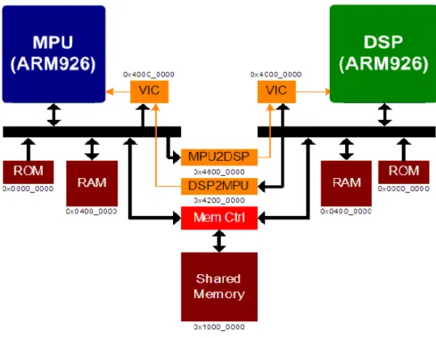
Let’s take a JPEG encode again on the developed dual core platform, as shown in Figure 1-6, to illustrate the latency within acceleration and to look into influences of IPC overhead. Figure 1-6 demonstrates a dual-core platform developed by CoWare, a SystemC-based electronic system level (ESL) tool which can rapidly create and validate SoCs in an early stage. It consists of two ARM926 processors connected by AMBA AHB, where one is considered as the MPU and the other acts as the DSP. Two ARM926s can access not only their own local memory but also the shared memory. In addition, the mailbox is applied and connected to the vector interrupt controller (VIC) to interrupt the corresponding processor. With mailboxes, ARM926s can be synchronized with each other.
Figure 1-6 Developed dual-core simulation platform on CoWare
Suppose that, for a realistic case, the operation frequency of the MPU is configured as 250 MHz, while the operation frequency of the DSP is 500MHz. then, the total latency for accomplishing the application on the dual-core platform will include the following four parts: (i) data movement to/from DSP; (ii) task management and memory management; (iii) mailbox handshaking and the response of the real-time kernel; (iv) task computation. To
encode a 256×256 JPEG image, the measured latency for the part-(i), (ii), (iii), and (iv), respectively, on CoWare is: 7963μs, 1,430μs, 31,242μs, and 17,981μs. Nevertheless, we do spend much time on IPC overhead in function partition scheme and it certainly degrades the system performance. We now consider the general case that the application may consist of the sequential part and parallel part. For achieving better performance, one may allocate the parallel tasks to the other (N-1)-core for data acceleration. Then, we have
overhead critical S seq iii ii i s para S seq para seq tot IPC T N T T T T N T N T T T T ) ( ) ( ) ( ) (
max
1 -N 1 (1-1)Where Ti( ), Tii(), and Tiii() denotes the latency of the part-(i), (ii), and (iii), respectively, for the -th core and Tpara() is the workload allocated to the -th core. Ns denotes speedup factor of each core. Among them, the maximum computation time for Tpara( ) is denoted Tcritical. And for simplicity, we use IPCoverhead to denote the inter-core communication overhead and time for necessary data movements. IPCoverhead is the hardware-dependent parameter, while Tcritical and Tseq are related to application’s characteristics as well as the degree of the workload balancing. If well workload balancing, we approach the best performance that Tcritical = (Ttot - Tseq) / Ns(N - 1). However, workload balancing and IPC overhead are important issues regarding multicore performance. Unfortunately, these primary factors are usually at odds with each other and must be traded off. Therefore, based on the streaming multimedia programming model, we propose an efficient design flow of parallelizing streaming multimedia applications on multicore architecture.
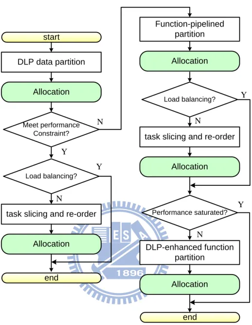
Function-pipelined partition
Allocation
Load balancing?
task slicing and re-order
Allocation Performance saturated? DLP-enhanced function partition Allocation end Load balancing?
task slicing and re-order
Allocation end N Y start DLP data partition Allocation Meet performance Constraint? Y N N Y Y N
Figure 1-7 Optimization flow for efficiently parallelizing multimedia applications on Multicore
The proposed design flow is shown in Figure 1-7. Various hardware-dependent factors and application-specific characteristics are involved in the design flow such that the designer can save several time-consuming iterations of partition and allocation steps. The algorithm starts from a streaming dataflow process network. To avoid frequent data movements and possibility unnecessary IPC overhead, the DLP data partition is prior and the data segment’s granularity is better as large as possible under system performance and local memory constraints. Raising data segment’s granularity will help data-level parallelism. However, it
will suffer from larger buffer or local memory. If the local memory of each core is not large enough, the performance could be degraded significantly due to inefficient data movements. After processes allocation, the algorithm checks whether it meets the performance constraints of the application. If yes, several hardware porting techniques to hide IPC overhead as well as data movements then fully utilize the hardware resources of the multicore are applied to achieve the best performance. The techniques include the workload balancing, multiple buffering and efficient local memory configurations. If the process allocation cannot attain workload balancing, especially the case that the consumption time of the critical process is more than twice as larger as that of other essential processes, the workload balancing techniques are considered. We apply evenly slicing the critical process, scrambling the processes and process reallocation to achieve workload balancing. As a result, the workload balancing DLP streaming data partition on multicore architecture is guaranteed. On the other hand, if the current data partition scheme cannot meet the performance constraint, the multi-stage (or software pipelined) function partition scheme is applied. We first decompose the application into processes by applying function partition. After investigating the characteristics of each process, the adequate process allocation, which will be discussed later, could be achieved. Similarly, we now check the degree of workload balancing after process allocation. If not, the technique of evenly slicing the critical process is applied. Then, reorder and re-allocate the processes are performed. It is sometimes happened that the number of essential processes, says K, is less than the number of available cores, says N, the multicore performance will be limited or saturated, since the gain in multicoreperformance will not be linearly proportional to N. To achieve the best performance, we consider the DLPenhanced parallel function partition scheme. By applying L-parallel, LK>N, unfolding of the workload-balancing function-partition process network, we may have enough essential processes to allocate for achieving the best performance.
1.4 Multi-resolution applications
Multi-resolution applications are special but pervasive uses in variety domain. It is applied in future multimedia applications, image processing and intelligent computer vision. For example, it can be used in image compression, such as JPEG 2000. JPEG 2000 is an image compression standard and coding system. It was created by Joint Photographic Experts Group committee in 2000 with the intention of superseding their original discrete cosine transfer-based JPEG standard (created in 1992) with a newly designed, wavelet-based method. One of design procedure is multiple resolution representation. And it also can be used in image pyramid process which is heavily used in a wide variety of vision applications. It develops filter-based representation to decompose images into multiple scales, to extract features/structures of interest, and to attenuate noise. Moreover, it also can be used in image detection which is our topic in this research. It is using multiple scales of search window to complete detect.
There are some application-specific characteristics of multi-resolution applications. (1) Repeated signal processing performs on different granularity. It performs identical operations on different resolution at same input data. Because of this reason, it has (2) multi-level data locality. Data use across resolutions is relativity. Furthermore, to process different granularity on one input data, it requires huge amount of data transfer to complete the operation. Therefore, multi-resolution applications are (3) communication-intensive process.
1.5 Problem formulation and contributions
Most manners of efficient parallelizing multimedia applications on distributed scratchpad memory multicore are focusing on intra-resolution process. In most of multimedia applications, a set of input data stream is accomplished by multiple computing kernels in
single granularity operation. Therefore, optimization flow for parallelizing on multicore is one-dimension exploration. However, for multi-resolution applications, it would introduce redundant memory transfer to interfere performance to linear speedup. Computing time is accelerated linearly by using multicore. Data transfer becomes the critical issue in communication-intensive process as multi-resolution applications. Hence, not only intra resolution optimization but inter-resolution data characteristic should be considered.
In this thesis, we propose a data-oriented task partition to take advantage of multi-resolution characteristics. We aim to reduce unnecessary memory transfer. Therefore, we can relieve loading of interconnect network and even avoid memory contention. Additionally, we propose a platform-dependent optimization flow for multi-resolution applications. By going through this optimization flow, we can guarantee balanced workload and low-data-transfer parallelization for multi-resolution applications. Experiment is set on PlayStation3 to evaluate performance. Cell is one typical distributed scratchpad memory multicore. By data-oriented task partition, we can accelerate 5.6 times of execution time on 6-core compared to CellCV version on 1-core. Data transfer is reduced 95% compared to CellCV.
1.6 Thesis organization
This thesis focuses on data-oriented task partition and optimization flow. This thesis is organized as follows.
Chapter 2 introduces algorithm of Viola and Jones object detection and resolution-based task partition on distributed scratchpad memory multicore. And then, we will mention about the proposed task splitting to generate extra tasks to overcome load imbalance..
handle in CellCV. Chapter 3 introduces the proposed optimizations. We will detailed illustrate the optimization principle and some temporary problems we would meet. And finally, we can fix these problems and got better performance.
Chapter 4 shows the experiment results by using our proposed task partition. Finally, chapter 5 concludes this thesis and points out the direction of future research.
2 M
ULTI
-
RESOLUTION
A
PPLICATIONS
In this chapter, we take Adaboost-based object detection as one case study. It is one of multi-resolution application. Firstly, we review Adaboost-based object detection, including detecting theorem and fast algorithm. And then, we mention features of object detection which lead to some implement mechanisms in distributed scratchpad memory multicore system. According CellCV simulation results, there are some problems we have to solve: load balance and data transfer issue. Proposed row-based splitting aims to overcome load balance issues. Although the performance is got improved by row-based splitting, but the memory access issue is not be considered. Data transfer’s waiting time is still increasing and occupying a great amount of execution time.
2.1
Object detection algorithm
Object detection based on image processing has become an active research area in computer vision field in recent years. For the evolving embedded applications rely on object recognition system such as automotive applications, surveillance, and intelligent robots, reliable object detection has major influence on the performance and usability the above systems. Viola and Jones have proposed a adaboost-based procedure that reduces the processing time substantially while achieving almost the same accuracy as compared to other methods (i.e. skin color, neural network, example-based, …etc.). This section is composed by four topics as introduced as follows,
Haar-feature
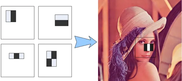
Adaboost-based object detection classifies images based on value of simple feature. There are many motivations for using feature rather than pixel directly. The most common reason is that features can act to encode ad-hoc domain knowledge that is difficult to learn using a finite quantity of training data. For this system there is also the second critical motivation for features: the feature-based system operates much faster than a pixel-based system. The simple feature are used reminiscent of Haar basis functions which have been used by Papergeorgiou et al. More specifically, they use two kinds of features. The value of the two-rectangle feature is the difference between the sum of pixels within two rectangular regions. The regions have the same size and shape and are horizontally and vertically adjacent (see figure 2-1). A three-rectangle feature computes the sum within two outside rectangles subtracted from the sum in a center rectangle.
Figure 2-1 Harr-like based object detection Cascade classifier feature0 feature1 feature2 feature0 feature1 Featuren-1 feature0 feature1 Featurem-1 Stage 0 Stage 1 Stage 21
Fail Fail Fail
Pass Candidate
Pass Pass
Figure 2-2 Cascade classifier
Haar-like features used are simply masks constituted by two to three rectangles. When utilized in object detection, pixels masked by white and black are summed up respectively. The
difference of summed up value are examined by a predefined threshold. A weak classifier is set if the summed up value exceed threshold. Weak classifiers produced by features are weighted averaged to produce strong classifier, which indicate whether the examined area is an object or non-object. Various strong classifiers are cascaded together as a degenerate decision tree. While maintaining classifiers cascaded in a proper order, detection rate can be raised without sacrificing detection time. In our research, we use the default file of adaboost-trained classifier which has 2135 features and 22 stages, as shown in figure 2-2.
Integral image
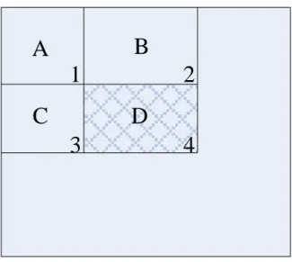
Rectangle features can be computed very rapidly using an intermediate representation for the image which we call the integral image. The integral image at location x, y contains the sum of the pixels above and to the left of x, y, inclusive:
y y x x y x i y x ii ' , ' ) ' , ' ( ) , ( , (2-1)where ii(x, y) is the integral image and i(x, y) is the original image. Using the following pair of recurrences:
s(x, y) = s(x, y-1) + i(x, y) (2-2)
ii(x, y) = ii(x-1, y) + s(x, y) (2-3)
(where s(x, y) is the cumulative row sum, s(x, -1) = 0 an ii(-1, y) = 0) the integral image can be computed in one pass over the original image.
A
B
C
D
1
2
3
4
Figure 2-3 Integral image
Each rectangle’s sum can be computed in four references of integral image (see figure 2-3). If we want to calculate the accumulated pixel of area D, we can just obtain by simple computation of (p1-p2-p3+p4). For one example, if we want to calculate an area of m×n pixels. We can reduce the complexity from m×n additions to 3 additions. This method can highly reduce computation complexity. Unfortunately, it is implying the problem with frequently memory accessing for the scatter data.
Scaling window scanning
OpenCV is a library originally proposed by Intel in 2002. It targets for computer vision applications on programmable platform.As OpenCV library gets more and more popular and is broadly used in various applications, it has been implemented on many platforms, including those with multicore architectures. CellCV is right the parallized implementation of OpenCV on Cell Broadband Engine. .
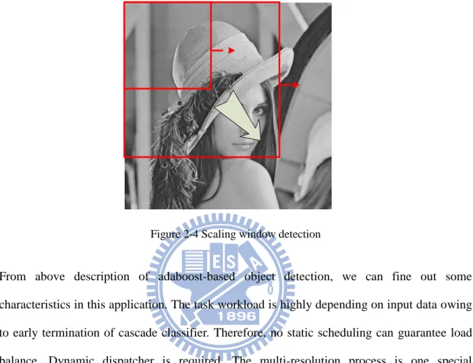
There are two detection approaches for adaboost-based detection. One is scaling window and the other is scaling image. In this thesis, we choose scaling window for detection mode. Because of our simulation platform is cell processor, we reference CellCV’s implementation. The detecting mechanism is using a scaling window to scan the whole image from low
resolution to high resolution. And it stops scaling till the window size out of one of image length (see figure 2-4).
Figure 2-4 Scaling window detection
From above description of adaboost-based object detection, we can fine out some characteristics in this application. The task workload is highly depending on input data owing to early termination of cascade classifier. Therefore, no static scheduling can guarantee load balance. Dynamic dispatcher is required. The multi-resolution process is one special characteristic in object detection. It contains repeated signal processing on same input data with different granularity.
Workload analysis
Object detection is made easy by OpenCV APIs. To verify performance of object detection in OpenCV, the latest OpenCV library is built on a 2.5GHz Xeon workstation with 8GB main memory running Linux. Face detection on different sizes using different scaling factors is evaluated. Table 2-1 summarizes the profiling using single thread. According to the result, object matching is the hot spot of object detection which occupy more than 95%
execution time in all cases. The overall detection time is dependent on image size and scaling factor. The detector can process QVGA image in realtime regardless of scaling factor. However, ability to process QVGA in realtime already becomes insufficient for today’s applications. As it has been reported that scaling factor = 1.2 has the best detection rate, we will focus on object matching for VGA image using scaling factor 1.2 hereafter
Table 2-1 Performance of row-based splitting
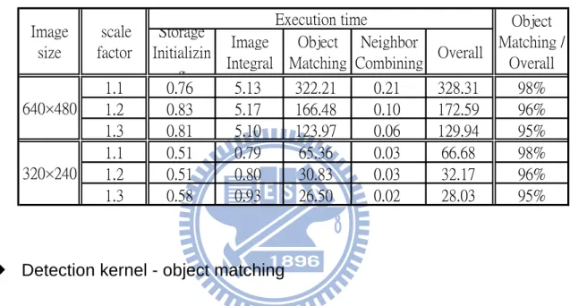
1.1 0.76 5.13 322.21 0.21 328.31 98% 1.2 0.83 5.17 166.48 0.10 172.59 96% 1.3 0.81 5.10 123.97 0.06 129.94 95% 1.1 0.51 0.79 65.36 0.03 66.68 98% 1.2 0.51 0.80 30.83 0.03 32.17 96% 1.3 0.58 0.93 26.50 0.02 28.03 95% 640×480 320×240 Object Matching / Overall Overall Image size scale factor Execution time Storage Initializin g Object Matching Image Integral Neighbor Combining
Detection kernel - object matching
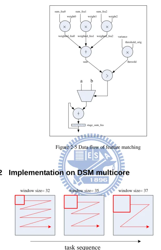
According to Table 2-1, we take object matching as computation kernel on DSPs. The whole operation can be divided into summed feature calculation, feature-threshold comparison and stage-threshold comparison. Figure 2-5 illustrates the detail of operations in feature calculation. The summed feature would be taken to multiply with a weight and then be summed into a value. Variance represents the pixel distribution for a specific search position and specific search window. It is taken to multiply with constant threshold to obtain feature-threshold. This value is taken to be compare with feature-sum and then decide the result is assign from value A and value B. Value A and value B are define while classifier training. Accumulate each result after going through every features, the final result is taken to compare with stage threshold. The result determines the following operation whether pass to next stage or not.
a b × × × + × + stage_sum_fea >
sum_fea0 sum_fea1 sum_fea2 weight0 weight1 weight2
variance threshold_orig weighted_fea0 weighted_fea1 weighted_fea2
sum thresold
Figure 2-5 Data flow of feature matching
2.2 Implementation on DSM multicore
window size= 32 window size= 35 window size= 37
task sequence
SPE Kernel() SPE Kernel() SPE Kernel() I0 I1 I2 I3 I4 I5 I6 O0 O1 O2 O3 O4 O5 O6 Output Queue Input Queue Issue order
Figure 2-7 Dynamic task scheduling mechanism – centralized task queue
Resolution-based task partition for object detection is taking a fixed window size as a single task, as shown in Figure 2-8. It generates a few number of tasks related to application’s parameter as scaling factor, image size and initial window size. Tasks are generated and enqueued to centralized input queue which is allocate in main memory. In Figure 2-9, all cores are pending on one input queue, and acquires new task after finishing previous task. As same as input task queue, each core puts the result into centralized output queue. After parallel procedure, serial part of application is continuously collecting results from main memory to perform complete application.
2.3
CellCV simulation results
In CellCV, it develops an optimization for implementing object detection on Cell. For search window smaller than 88×84, it allocates a small window buffer to faster access. Because of accessed data in small window is more gather, CellCV loads a block of data from main memory into small window buffer. It can avoid frequent memory access to main
memory by this optimization. But for search window bigger than 88×84, it accesses feature value while detecting. It is because the required data in bigger window is out of small window buffer. And it implies concurrent memory access with parallel processing in multicore by frequently data transfer.
1.91 2.71 3.37 3.82 4.16 1 1.5 2 2.5 3 3.5 4 4.5 2 3 4 5 6 core number sp ee du p
Figure 2-8 Speedup curve @ 2~6 SPE
On Sony PlayStation3, a typical distributed scratchpad memory multicore with 6 cores, we take VGA size (640×480) image to evaluate the performance. The parameter settings in algorithm as follows: scaling factor is 1.1 and initial scaling window is 30×30. We can find out in Figure 2-7, performance is become saturated with increasing core number. The speedup factor is interfered to linear grow up. It only obtains 4.16 times speedup using 6 cores. It is under our expectation.
By further analysis, parallel object detection of CellCV suffers from load balance and memory transfer issue. Figure 2-8 illustrates task distribution of object detection on 6 cores. Execution time of each task is further categorized into computing and waiting. Computing
stands for time calculating feature sums while waiting indicates time waiting memory transfer operations to ship required data in. As in the distribution, total execution time is dominated by a single core while devotes itself to detection of smallest object. For other cores, about 20% execution time is wasted idling. In addition, about 30% time is spent waiting memory transfer operations. These effects prevent us from getting linear speedup.
0 1 2 3 4 5 c o re id idle
Exe. time on single core Memory contention time
Figure 2-9 Workload distribution on 6-SPE @ 1.1 scaling factor and 640×480 image
0.8 1 1.2 1.4 1 2 3 4 5 6 core number w or kl oa d (n or ma li ze d to 1 c or e)
Figure 2-10 Workload comparison (normalized to single core)
are deployed, the total workload is gradually increasing. The extra overhead comes from data transfer waiting. It achieves 1.35 times of workload using 6 cores. And this result implies the problem of memory transfer is a critical issue in future multicore platform.
2.4
Task Reorder and Row-Based Splitting
Task reorder and row-based splitting is proposed to overcome the workload balance problem. This paper further analyzes the task workload in CellCV implementation. As in Figure 2-10,CellCV diverse into two different implementation styles, one for search window smaller than 88×84, and the other services for larger search window. Take object detection for VGA image in scaling factor 1.2 using 5 SPEs as an example. Each bar represents a task. The height of bars indicates the actual execution time of each task on SPE. Time wasted in memory contention is marked using light color. Red bar stands for small window task while blue one suggest large window task. In Figure 2-14, it is obvious that the detector suffers from poor load balancing. SPE1 who is in charge of task4 and task5 become bottleneck. If the task with heavy workload, task5, can be issued earlier, a free SPE can be allocated to take care of it.
Figure 2-12 Task allocation using 5-SPE in CellCV
Figure 2-13 Interleaved task reorder
Proposed interleaved task reorder can re-schedule the task sequence in non-increasing workload order to achieve load balance, as shown in Figure 2-13. Somehow, if there are extremely heavy tasks dominating the whole execution, reorder is helpless. Figure 2-16 is an example of object detection by 6 cores. Memory contention problem become more critical using 6 SPE, which increase execution time of task5 and make it the dominating task. Proposed row-based splitting generates additional task partition by further partition tasks. Each task now is in charge of object detection of specific size on several rows, as illustrated in Figure 2-17. Compared to task reordering, row-based splitting can efficiently obtain load balance. Table 2-1 lists the performance comparison of CellCV and row-based splitting as scaling factor being 1.1, 1.2 and 1.3. .
Figure 2-14 task allocation using 6-SPE in CellCV
Figure 2-15 Row-based task splitting
Table 2-2 Performance of row-based splitting Improvement Performance (fps) 1.1 3.8 7% 4.1 1.2 7.6 10% 8.5 1.3 8.2 13% 9.5 640×480
CellCV (fps) Row-based splitting Scale
factor image size
2.5
Observation
Memory transfer issue is neglected by above parallelization. Memory transfer time is becoming the critical part in execution time as shown in Figure 2-18. Light color, which denotes memory contention time, occupies a great amount of ratio in execution time. In communication-intensive process as multi-resolution applications, data transfer and memory contention really degrade the system performance. Moreover, memory contention would more and more serious by all processors sharing a memory resource. As core number increasing, memory contention becomes critical problem in multicore. For distributed scratchpad memory multicore, software programming in data transfer requires addition effort to avoid unnecessary memory transfer. Efficient data use in local buffer is important to reduce redundant memory access. Therefore, we propose a new task partition to take care of memory transfer as described in follow chapter.
3 D
ATA
-O
RIENTED
T
ASK
P
ARTITION
In this chapter, we propose a data-oriented task partition to take advantage of multi-resolution application’s characteristic. We use tile-based scanning to consider not only inter-resolution data locality but also intra-resolution data use efficiency. Furthermore, we can elaborate superior performance by a platform-dependent optimization flow. According to these methods, we can construct balanced workload and low-data-transfer task partition for multi-resolution applications.
3.1 Data-oriented task partition
Object detection is one of multi-resolution application. It performs detection on different resolutions based on one input data. It contains multi-level data locality among resolutions. Therefore, we propose a new task partition to maintain data locality across resolutions and avoid unnecessary memory access comparing with resolution-based task partition. Data-oriented task partition takes ―data use‖ for one criterion. Once a portion of data is brought into scratchpad memory, we will try to make best use of the data. As shown in Figure 3-1, we substitute the resolution-based task partition to the data-oriented task partition. Differing from resolution-based task partition, we further take care of data use in multi-dimension. We aims to reduce unnecessary data transfer to optimize for communicate-intensive application. By reducing unnecessary memory transfer, we can prevent the memory contention happening and improve the performance to linear acceleration.
TLP
res 0 res 1 res 2 Window scale up res 0 res 1 res 2Figure 3-1 Data-oriented task partition differs from resolution-based partition
3.2 Tile-based Scanning
Management of memory transfer is important for distributed scratchpad memory multicore. So, we care about data use in local store buffer. In one specific resolution, we
propose a tile-based scanning to reduce the unnecessary memory access for intra-resolution procedure. The input image is cut into tiles which is a basic task partition unit. But the tile’s size is restricted by small window buffer size. In small window optimization, the largest size for small window buffer is (small_window_width × feature_sizemax). In CellCV, the small
window buffer is 176×84. But in low resolution, feature size is far shortened from 84. There is some reserved memory space for storing integral image which is idle in low resolution case. It is kind of waste in resource. Therefore, under the small window buffer constraint, we can load multiple row data block into scratchpad memory for computing multiple row process at the same time. By this way, we can reduce redundant memory access. As illustrate in Figure 3-2, we use 176×84 size of buffer to be a tile. Tile-based scanning becomes a basis in this optimization.
Figure 3-2 Tile-based scanning
We can use a simple memory access model to analysis before simulation. The function f means the data transfer size. This function is related to window size (s), image width (W), image height (H), tile width (w) and tile height (h). So the data transfer for on specific resolution in CellCV can be modeled as follow,
s)/s -(H 2) (s W 40 s)/(s/20)) -((H (W/(w/2)) 2)) (s w ( itr_y itr_x e buffer_siz h) w, H, W, (s, f ( -)
And the data transfer for specific resolution in tile-based scanning can be modeled as follow, H W 2 (H/h) (W/(w/2)) h) w ( itr_y itr_x e buffer_siz h) w, H, W, (s, f ( -)
By this data transfer model, we can reduce data transfer size about 7 times of reduction for one specific resolution in Table 3-1. Using this optimization can more reduce data transfer size for intra-resolution operation.
Table 3-1 Static analysis of tile-based scanning
W=640 H=480 w=176 h=84
cellcv
tile-based
32
35,840
4,800
7.47
35
38,938
4,800
8.11
Analytical data transfer size (KB)
s
Reduction
Applied in data-oriented task partition, computation referencing the same tile would be collected in the same task. We use the data as could as possible in the tile. By this way, we take advantage of all available data locality.
3.3 Difficulty and Overhead
To maintain the identical function behavior, it would introduce memory access overhead for X-direction and Y-direction. Moreover, it has another constraint for tile shifting in
X-direction. The memory transfer has to be alignment access. So the tile’s shift has to map to multiple of 16-byte to prevent bus error. And it equals to 4-pixel. Consequently, the X-direction incurs more serious boundary issue.
image tile image tile image tile x-direction y-direction
Figure 3-3 Boundary issue in X-direction and Y-direction
In Figure 3-3, it illustrates the boundary problem of tile-based scanning. In left graph, computation, across resolutions, belong to this tile would be executed while this tile of data is brought in local memory. But there exists some computation’s data which portion of data is within in tile and rest is out of tile. This incurs both in X-direction and Y-direction. In X-direction, shown in right-up graph, there is an overlap data range between current tile and previous tile. Overlap data is extra memory transfer to maintain same behavior.
3.4 3-Step Optimization Flow
By using data-oriented task partition can improve performance via concerning memory access issue. Furthermore, we can find out there are some parameters would effect the performance enhancement. The small window implementation highly depends on tile size. The peak performance is related to the number of resolution using small window implementation. Therefore, we propose a platform-dependent optimization flow to elaborate the superior performance. This flow can enhance the data-oriented task partition by three steps as follow. Firstly, we would consider the data allocation in local store. By a simple experiment, we can re-arrangement the data structure stored in local store. Then we can discuss the tile-shape affecting to the performance. Following, we would explore the relativity between task granularity and performance. The entire flow is illustrated in Figure.
Data allocation
Tile-shape exploration
Granularity exploration start
end
Data allocation
This step is to discuss the data allocation in local store. In object detection, the main data structures are kernel program, classifier and integral image (for small window buffer). In CellCV implementation, it considers the frontal stages of classifiers are often used for detection. To be convenient for execution and avoid frequent memory access, it loads frontal-stage classifiers into local store buffer. Rest-stage classifiers is used ping-pong buffer to load while detecting. And it allocates 176×84-pixel of size as small window buffer for storing integral image. And the small window buffer’s size could affect the performance by influence the number of resolution using small window optimization.
Except kernel program, our expectation is extending small window buffer to support more resolutions for small window optimization. Therefore, we can use a simple application-level analysis to be guideline for tradeoff between classifier and integral image.
0 20,000 40,000 60,000 80,000 100,000 1 2 3 4 5 6 7 8 9 10 11 12 13 14 15 16 17 18 19 20 21 22 23 stage # of ca nd id at e
Figure 3-5 Application-specific analysis of classifier
Figure 3-5 is a curve of rejection distribution for detecting candidate. Horizontal -axis means stage-id. And vertical-axis means number of candidates. For first dot illustrate about
70,000 candidates are rejected at first stage, and so on. According to this result, 60 percent of candidates are rejected at second stage and 90 percent of candidates are rejected at fifth stage. It reminds us that the utility of classifier is focusing on frontal five stages. We can shorten the size of resident classifier and expand the small window buffer under the memory size constraint. But we can not sure about five stages of classifier as resident classifier can gain the best performance in Cell processor. So we also use simulation-based analysis to find the solution. In Figure3-6, X-axis represents the number of features storing as resident classifier. Y-axis represents the execution time in mini-second. Therefore, we can find out the peak performance happening at seven-stage. And the small window buffer can extend to 192×96 pixels as tile size.
400 420 440 460 480 500 520 540 560 580 600 35 85 135 185 235 285 335 385 # of stage Ex e . ti me (ms)
Figure 3-6 Hardware-dependent analysis of classifier
Tile-shape exploration
After previous analysis, we can confirm the data allocation is the best. And the small window size is also decided. How to use this small window buffer efficiently is a critical issue. Hence, this step we want to discuss the tile-shape affecting to performance. Different shape can introduce distinct level of boundary problem not only in X-axis but also Y-axis.
Additionally, it can affect number of resolution implemented in small window optimization. Like slender tile would restrict the resolution implemented in small window mode by shorter side. Consequently, we want to analyze this issue. As shown in Figure 3-7, X-axis represents the tile’s width from short to long and the tile’s length vice versa. We can get the optimal point at w=h (square). This result is as our expectation because of more resolutions using small window buffer in square. But a fixed size of small window buffer can not map to square perfectly all the time. Therefore, this exploration can choose the tile shape to appropriate using small window buffer. The case-(w>h) is better than case-(w<h). It is because of window shifting in X-direction must to be mapped to multiple of 16-byte (alignment access). And case-(w<h) would introduce more times of tile’s movement in X-direction. It would cause more redundant memory access.
400 410 420 430 440 450 460 80 100 120 140 160 180 200
Tile width (pixel)
E x e . tim e ( m s )
Figure 3-7 Tile-shape analysis
Granularity exploration
Different level of task granularity leads to two issues. Less task number would pose the disadvantage of imbalance workload. Numerous tasks would increase software overhead of
grabbing tasks from centralized queue. Therefore, this step wants to analyze the relativity between different level of granularity and performance. In this experiment, we discuss the case of uniform task. We can merge multiple tasks into a packed task to shorten the task instance. In the reality case of this experiment, the task partition in regular implementation is referencing to resolution-based task partition while the task number in small window implementation is controllable after adjusting tile size. However, this configuration would introduce workload imbalance because of inappropriate task sequence. The former tasks which come from small window implementation are finer than latter tasks which come from regular implementation. Therefore, we finer partition the tasks in regular implementation as position level. And we use task merging into uniform tasks to analysis task granularity influencing performance. In Figure 3-8, it is a simulation-based analysis to find the optimal solution. The horizontal axis denotes the task granularity in binary logarithm. And the vertical axis denotes execution time. By this result, we can find out average 512 task instances perform superior performance with uniform task merging.
395 400 405 410 415 420 425 430 435 440 445 4 5 6 7 8 9 10 11 12 13
task granularity (log2(task_num))
E xe. ti m e( m s)
3.5 Design results
3.5.1 Memory access 12075 12075 378 0 2000 4000 6000 8000 10000 12000 14000 cellcv row-based splitting data-oriented task partition me mr oy a cc ess c ou ntFigure 3-9 Access count comparison
414115.625 414115.625 21800.625 0 50000 100000 150000 200000 250000 300000 350000 400000 450000 cellcv row-based splitting data-oriented task partition T ot al t ra nsf er si ze ( K B )
Figure 3-10 Transfer size comparison
Tile-based scanning and data-oriented task partition are proposed to reduce redundant memory access in CellCV. Therefore, we firstly compare memory access count and data transfer for each version as shown in Figure 3-9 and Figure 3-10. Row-based splitting is
proposed to optimize workload distributed on each core. Hence, it has the same quantity of memory access count/data transfer size as CellCV. And data-oriented task partition can reduce 97% memory access count and 95% data transfer size comparing to CellCV.
3.5.2 Workload balance
This thesis concerns about the memory access issue which is rarely to discuss for multicore platform. Data-oriented task partition not only reduces memory access but also takes care of workload balance. In Table 3-2, we list the workload distribution of each version. We define the idle time represented by (the longest idle time within 6 SPEs / finish time). We choose the worst case to evaluate workload distribution with each implementation. In CellCV, the task is partitioned in high level which generates less task instance. It takes resolution-based task partition. Only 29 tasks are parallelized on 6 SPEs. It would cause serious workload imbalance. Row-based splitting can shorten the idle time from 10.01% to 3.22% by creating extra task instance. And by our optimization flow, data-oriented task partition can shorten to 2.15%.
Table 3-2 Workload balance comparison
Version cellcv row-based splitting data-oriented partition Task Number 29 34 512
idle 10.01 3.22 2.15
4 E
XPERIMENT
R
ESULTS
In this thesis, we use a Cell processor to simulate the entire experiment. It is one of typical distributed scratchpad memory multicore. And we take adaboost-based object detection as one case study. Proposed data-oriented task partition not only can reduce memory access but also attain workload balance. The experiment results would be compared to CellCV and row-based task splitting in execution time, acceleration and frame-rate.
4.1 Cell Architecture
Figure 4-1 shows a high level block diagram of the CBE processor hardware. The CBE processor is a multicore processor with 9 processor elements in total and a shared coherent memory on-a-chip. The functionality of processors can be categorized into two kinds. One is the PowerPC Processor Element (PPE) and the other is the Synergistic Processor Element (SPE). There are one PPE and eight identical SPEs. All processor elements are connected to each other and to the on-chip memory and I/O controllers by the memory-coherent element interconnect bus (EIB).
Figure 4-1 Block Diagram of Cell Broadband Engine
PowerPC Processor Elements
The PowerPC Processor Element (PPE) is a general-purpose, dual-threaded, 64-bit RISC processor that conforms to the PowerPC Architecture, with the vector/SIMD multimedia extensions. The PPE consists of two main units, the PowerPC processor unit (PPU) and the PowerPC processor storage subsystem (PPSS) as shown in Figure 4-2.
Figure 4-2 PPE Block Diagram
The PPU performs instruction execution. It has a level-1 (L1) instruction cache and data cache and six execution units. It can load 32 bytes and store 16 bytes independently and memory-coherently, per processor cycle. The PPSS handles memory requests from the PPU and external requests to the PPE from SPEs or I/O devices. It has a unified level-2 (L2) instruction and data cache. The PPU and the PPSS and their functional units are shown as Figure 4-3.
PPU could further divided into the following functional units.
Instruction Unit (IU)
The IU contains a 2-way set-associative and reload-on-error 32KB L1 instruction cache. The cache-line size is 128 bytes. The IU performs the instruction-fetch, decode, dispatch, issue, and completion portions of execution.
Branch Unit (BRU)
The BRU performs the branch functionality.
Fixed-Point Unit (FXU)
The FXU performs fixed-point operations, including add, multiply, divide, compare, shift, rotate, and logical instructions.
Load and Store Unit (LSU)
The LSU contains a 4-way set-associative and write-through L1 data cache with 32 KB. The cache-line size is 128 bytes. The LSU performs all data accesses, including load and store instructions.
Vector/Scalar Unit (VSU)
The VSU contains a floating-point unit (FPU) and a 128-bit vector/SIMD multimedia extension unit (VXU), which together execute floating-point and vector/SIMD multimedia extension instructions.
Memory Management Unit (MMU)
The MMU contains a 64-entry segment look-aside buffer (SLB) and 1024-entry, unified, parity protected translation look-aside buffer (TLB). The MMU manages address translation for all memory accesses.
The PPSS handles all memory accesses by the PPU and memory-coherence operations from the element interconnect bus (EIB). The PPSS has a unified, 512-KB, 8-way set-associative, write-back L2 cache with error-correction code (ECC). The cache-line size for the L2 is 128 bytes as the same as L1 cache-line size. The PPSS performs data-prefetch for the PPU and bus arbitration and pacing onto the EIB. There are MMU, L1 instruction cache, and L1 data cache of PPU getting data from PPSS by a shared 32-byte load port. There are MMU and L1 data cache of PPU putting data to PPSS by a shared 16-byte store port. The interface between the PPSS and EIB supports 16-byte load and 16-byte store buses. One storage access occurs at a time, and all accesses appear to occur in program order. The interface supports resource allocation management.
Synergistic Processor Elements
The eight Synergistic Processor Elements (SPEs) execute a new single instruction, multiple data (SIMD) instruction set—the Synergistic Processor Unit Instruction Set Architecture. Each SPE is a 128-bit RISC processor specialized for data-rich, compute-intensive SIMD and scalar applications. It consists of two main units, the synergistic processor unit (SPU) and the memory flow controller (MFC), as shown in Figure 4-4.
The LS is a 256 KB, error-correcting code (ECC)-protected, single-ported, noncaching memory. It stores all instructions and data used by the SPU. It supports one access per cycle from either SPE software or DMA transfers. SPU instruction prefetches are 128 bytes per cycle. SPU data access bandwidth is 16 bytes per cycle, quadword aligned. DMA-access bandwidth is 128 bytes per cycle. DMA transfers perform a read-modify-write of LS for writes less than a quadword.
Each SPU has its own MFC. The MFC serves as the SPU’s interface, by means of the element interconnect bus (EIB), to main-storage and other processor elements and system devices. The MFC’s primary role is to interface its LS-storage domain with the mainstorage domain. It does this by means of a DMA controller that moves instructions and data between its LS and main storage. The MFC also supports storage protection on the main-storage side of its DMA transfers, synchronization between main storage and the LS, and communication functions (such as mailbox and signal-notification messaging) with the PPE and other SPEs and devices.
Figure 4-5 shows the SPE functional units. The SPU issues two instructions to its two execution pipelines respectively. The pipelines are referred to as even (pipeline 0) and odd (pipeline 1). Whether an instruction goes to the odd or even pipeline depends on the instruction type. The functional units in SPU are described as follows.
SPU Odd Fixed-Point Unit (SFS)
The SFS executes byte shift, rotate mask, and shuffle operations on quadwords.
SPU Load and Store Unit (SLS)
The SLS executes load and store instructions and hint for branch instructions. It also handles DMA requests to the LS.
SPU Control Unit (SCN)
The SCN fetches and issues instructions to the two pipelines. It performs control functions such as branch instructions, arbitration of access to the LS and register file, etc.
SPU Channel and DMA Unit (SSC)
The SSC manages communication, data transfer, and control into and out of the SPU.
SPU Even Fixed-Point Unit (SFX)
The SFX executes arithmetic instructions, logical instructions, word SIMD shifts and rotations, floating-point comparisons, and floating-point reciprocal and reciprocal square-root estimations
SPU Floating-Point Unit (SFP)
The SFP executes single-precision and double-precision floating point instructions, 16-bit integer multiplies and conversions, and byte operations. The 32-bit multiplies are implemented in software using 16-bit multiplies.
Element Interconnect Bus
Figure 4-6 shows the element interconnect bus (EIB), which is the communication path for data commands and data among the PPE, SPEs, main system memory, and external I/O. The EIB data network consists of four 16-byte-wide data rings: two running clockwise and the other two counterclockwise. Each ring allows up to three concurrent data transfers, as long as their paths don’t overlap.
Figure 4-6 Element Interconnect Bus (EIB)
To initiate a data transfer, bus elements must request data bus access. The EIB data bus arbiter processes these requests and decides which ring should handle each request. The arbiter always selects one of the two rings that travel in the direction of the shortest transfer, thus ensuring that the data won’t need to travel more than halfway around the ring to its destination. The arbiter also schedules the transfer to ensure that it won’t interfere with other