適用於IEEE 802.11及IAPP無線網路的快速換手機制
33
0
0
全文
(2) 適用於 IEEE. 802.11 及 IAPP 無線網路的快速換手機制. 學生:黃炳榮. 指導教授:曾煜棋 教授. 國立交通大學電機資訊學院 資訊學程﹙研究所﹚碩士班. 摘. 要. 在以 IEEE 802.11 為基礎建設的網路中,換手一直是一個嚴重的問題。 在這篇文中,我們將針對以 IEEE 802.11 結合 IAPP 的網路,提出一個快速 且無縫的換手機制。我們所提出的方法,是結合基於 neighbor graph 的概念、 加上一個在睡眠模式中執行選擇性掃描的方法、在換手之前預先執行認證的 機制和經由加強 IAPP 而延伸出來的 forwarding-and-buffering 機制。選擇性 掃描可以讓 mobile host (MH)縮短掃描鄰近 access points (APs)的時間;在換 手之前預先執行認證的機制也可以有效縮短換手的時間;而在利用 forwarding-and-buffering 機制,可以避免在換手過程中,資料的遺失。經由 我們的效能分析,我們所提出的方法,可以有效的減少 90%的換手時間, 且在換手的過程中,不會有資料的遺失。. i.
(3) A Fast Handoff Mechanism for IEEE 802.11 and IAPP Networks. student:Ping-Jung Huang. Advisors:Dr. Yu-Chee Tseng. Degree Program of Electrical Engineering Computer Science National Chiao Tung University. ABSTRACT. Handoff is a critical issue in IEEE 802.11-based wireless networks. In this paper we propose a fast and seamless handoff solution for IEEE 802.11 wireless LAN with IAPP. It is based on a concept of neighbor graph, which describes the nearby access points (APs) that a mobile host (MH) may find. Then we further derive selective scanning with unicast in power-save mode, pre-registration of IAPP, and frame forwarding-and-buffering mechanisms. Selective scanning allows a MH to only try potential handoff targets. Pre-registration allows early transfer of a MH’s security context from its old AP to new AP. The forwarding-and-buffering mechanism is to solve the packet loss problem during handoff. Our performance evaluation shows that the proposed solution can result in 90% reduction in the handoff latency from standard handoff procedure.. ii.
(4) 目錄. 中文摘要………………………………………………………………………………………i 英文摘要……………………………………………………………………………………...ii 目錄…………………………………………………………………………………………..iii 表目錄………………………………………………………………………………………..iv 圖目錄………………………………………………………………………………………...v I. II.. Introduction………………………………………………………………………………1 Related Work……………………………………………………………………………..2 A. IEEE 802.11 Handoff Schemes……………………………………………………….2 B. Inter Access Point Protocol (IAPP)……………………………………………………6 III. Experiment for handoff latency measurement…………………………………………...9 IV. The Proposed Fast and Seamless Handoff Mechanism…………………………………17 V. Performance Discussion………………………………………………………………...24 VI. Conclusions…………………………………………………………………………......25 Reference………..…………………………………………………………………………….26. iii.
(5) 表目錄 Table I. Detail specification of experiment environment………………………………………9 Table II. The result of experiments……………………………………………………………16 Table III. NG table…………………………………………………………………………….18. iv.
(6) 圖目錄 Figure 1. Two operation mode of IEEE 802.11………………………………………………..2 Figure 2. Extended service set…………………………………………………………………3 Figure 3. IEEE 802.11 handoff procedure……………………………………………………..5 Figure 4. The handoff procedure in IAPP………………………………………………………8 Figure 5. Experiment architecture………………………………………………………………9 Figure 6. Data rate of simulating traffic generated by MGEN………………………………..12 Figure 7. The effect of active scan to data transmission (experiment one)…………………...14 Figure 8. The effect of active scan to data transmission (experiment two)…………………...15 Figure 9. The effect of active scan to data transmission (experiment three)………………… 15 Figure 10. The system architecture of our fast and seamless handoff mechanism……………18 Figure 11. The proposed pre-registration and forwarding-and-buffering mechanisms for IAPP………………………………………………………………………………………...…19 Figure 12. The state machine of NG Client…………………………………………………...20 Figure 13. Handoff life cycle of our approach……………………………………………...…22 Figure 14. Change of signal strengths during handoff……………………………………...…23. v.
(7) I. INTRODUCTION Recently, the IEEE 802.11 wireless LAN (WLAN) [1] has grown rapidly due to its easy operation, low cost, and high throughput. Many applications, such as Voice over IP (VoIP), instant message, and media-streaming services, have been proposed to run on top of WLANs. However, handoff, an inherent problem with wireless networks, especially for real-time applications, has not been well addressed in IEEE 802.11. IEEE 802.11 takes a hard handoff approach, which means that a mobile host (MH) has to break its connection with its old access point (AP) before connecting to a new AP. This may result in long handoff latency. According to [2], it is found that the handoff procedure in IEEE 802.11 normally takes hundreds of milliseconds and almost 90% of the handoff delay is due to search of new APs, or so-called the probe delay. This is unsatisfactory because, for example, the recommended maximum handoff latency for VoIP applications is 50 ms [3]. In this paper, we propose a fast and seamless mechanism for IEEE 802.11 networks that support IAPP. During handoff, to select the next AP, a MH does not scan all channels. Instead, it only selectively scans some potential APs with unicast based on the neighbor graph (NG) provided by a NG Server [4]. We enhance the NG approach [4] by putting the MH to power-saving mode to pre-scan neighboring APs. Then we further derive selective scanning with unicast in power-save mode, pre-registration of IAPP, and frame forwarding-and-buffering mechanisms. Selective scanning allows a MH to only try potential handoff targets. Pre-registration allows early transfer of a MH’s security context from its old AP to new AP. The forwarding-and-buffering mechanism is to solve the packet loss problem during handoff. Section 2 reviews related work. The experiments for handoff latency measurement are stated in Section 3. We introduce our fast and seamless handoff mechanism in Section 4. Performance issues are discussed in Section 5. Conclusions are drawn in Section 6.. 1.
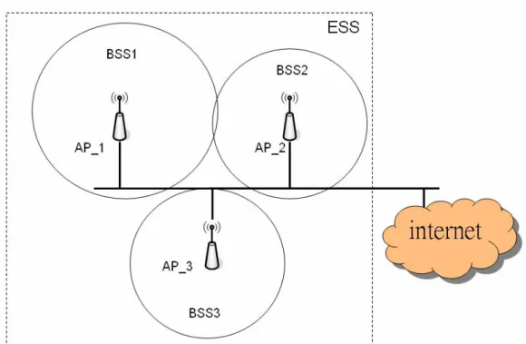
(8) II. RELATED WORK A. IEEE 802.11 Handoff Schemes IEEE 802.11 standard [1] defines two operation modes: infrastructure and ad hoc modes as shown in fig.1. In the infrastructure mode, an AP comprises a Basic Service Set (BSS) and provides connectivity to networks for their associated MHs. One or more APs comprise an Extended Service Set (ESS) to cover a larger area as illustrated in Fig. 2. In ad hoc mode, two or more MHs can form a peer-to-peer network without AP.. (a) Ad hoc mode. (b) Infrastructure mode. Figure 1. Two operation mode of IEEE 802.11. An ideal WLAN provides successive radio signal coverage for MHs in its service area. A MH may decide to handoff from an AP to another AP due to mobility, loading of AP, or fading of signals. The handoff procedure of IEEE 802.11 can be divided into two steps: discovery and reauthentication [2].. 2.
(9) Figure 2. Extended service set.. 1) Discovery: In order to find a nearby AP, a MH scans all channels either passively or actively. In passive scanning, a MH listens to APs’ periodic beacon messages to know their parameters, such as beacon interval, capability information, BSSID, supported rate, etc. The period of beacon frames is normally set to 100 ms in most implementations. In active scanning, for every channel, a MH will broadcast a probe request and expect probe responses from APs. In active scanning, the scanning delay can be calculated as [4]: Nch · Tb ≤ t ≤ Nch · Tt.. (1). Where Nch is the total number of channels (normally, Nch = 12 for 802.11a and Nch = 11 for 802.11b/g), Tb = MinChannelTime is the minimum time that a MH has to wait on a channel if no response is received, and Tt = MaxChannelTime is the maximum time that a MH has to wait on a channel if responses are received. In most implementations, the MaxChannelTime is set to 30 ms, which implies that the worst delay of active scanning, for example, in IEEE 802.11b is 300-400 ms. An experimental result can be found in [4].. 3.
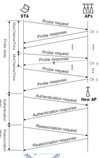
(10) 2) Reauthentication: This typically involves the authentication and reassociation procedures. The reauthentication phase transfers the credentials of the MH from the old AP to the new AP. IEEE 802.11 defines two subtypes of authentication service: 1) Open System, which is a null authentication algorithm and 2) Shared Key, which is a four-way authentication mechanism. If IAPP is used, only null authentication frames need to be exchanged in the reauthentication phase. In our experience, exchanging null authentication frames takes about 1-2 ms. After authentication, the reassociation process involves exchanging reassociation request, and reassociation response frames. From our experience, the reassociation delay takes around 1-2 ms. In IEEE 802.11 with IAPP networks, additional IAPP messages between the old AP and the new AP will increase the reassociation latency to 40 ms [5]. Fig. 3 summarizes the handoff procedure. The overall latency is more than 300 ms (including IAPP message overhead). The probe delay constitutes the biggest part (over 90%) of the delay [2]. The objective of our proposal is to reduce the handoff latency to less than 50 ms in order to support most of real-time applications.. 4.
(11) Figure 3. IEEE 802.11 handoff procedure.. To reduce the handoff latency, many approaches [4, 10, 11, 12, 13] have been proposed. Reference [4], a concept called neighbor graph (NG) is proposed. From the NG provided by an external server, a MH only needs to scan the channels that are used by its current AP’s neighbors. According to [4], about 10 ms are needed to scan a specific neighbor. In this paper, we will propose a selective scanning mechanism to farther reduce the search time. Reference [10] shows how to calculate the optimal MaxChannelTime, MinChannelTime, and beacon interval. However, it still has to scan all channels. Reference [11], it is suggested that when scanning a channel, a MH will evaluate the. 5.
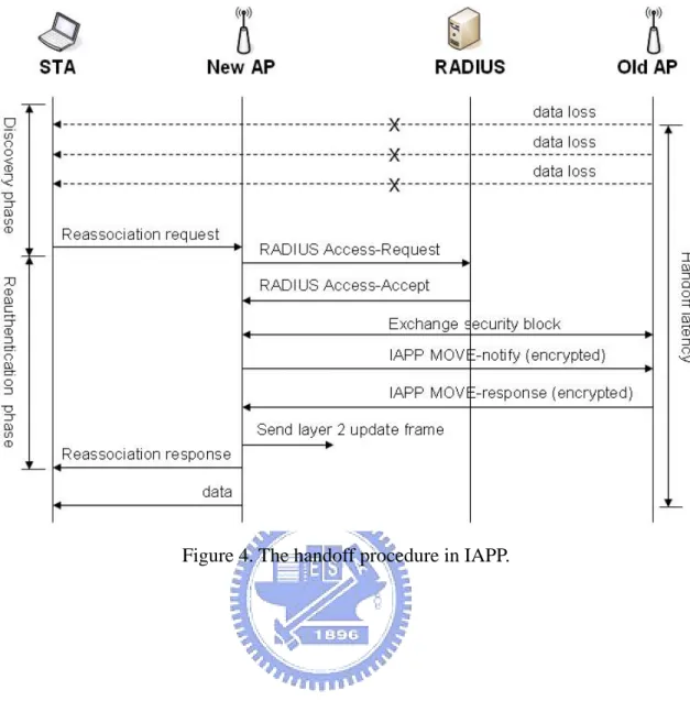
(12) number of APs (say Y) in that channel by monitoring packets sent in that channel. The MH will stop scanning that channel whenever it has collected probe responses from at least Y APs so as to reduce the scanning time. However, the scheme still has to scan all channels. Some fast handoff solutions focus on bypassing the scanning phase [12] [13]. Reference [12], a MH maintains a cache which contains a list of APs adjacent to its current AP. The cached data was established from its previous scanning. Only the two APs with the best received signal strength indication (RSSI) were cached. During handoff, the cached APs are searched first. If this fails, a selective scanning is performed. However, when the cache is obsolete, scanning is still inevitable. Reference [13], a MH can predict its movement path and select the potential AP. A location server can provide information about APs so that a MH can re-associate with its new AP directly without going through the probe procedure. However, this scheme relies on a precise localization method.. B. Inter Access Point Protocol (IAPP) To reduce the opportunity of transmitting security information of MHs in the air during the handoff period, IAPP proposes to allow an AP to communicate with other APs to exchange relevant information of associated MHs on a common DS. An IEEE 802.11 with IAPP network typically comprises APs, MHs, and Remote Authentication Dial In User Service (RADIUS) servers [14]. The RADIUS servers provide two functions: 1) mapping of the BSSID of an AP to its IP address on the distribution system medium (DSM) and 2) distribution of keys to APs to allow secure communications between APs [6]. The handoff procedure in IAPP is illustrated in Fig. 4. When a MH moves away from its current AP, it may start to search for a new AP by active or passive scanning. If a new AP is located, the MH will send a reassociation request frame to the new AP. The request frame. 6.
(13) contains MH’s MAC address and the BSSID of the old AP. Upon receiving the reassociation request frame, the new AP sends a RADIUS Access-Request packet to the RADIUS server to verify the old BSSID. If the old AP is valid, the RADIUS server will reply to the new AP a RADIUS Access-Accept packet which contains a security block for communication between the old AP and the new AP. Then the new AP will send an encrypted IAPP MOVE-notify packet to the old AP, which will reply an encrypted IAPP MOVE-response packet with the context information pertaining to the MH. Upon receiving the IAPP MOVE-response packet, the new AP will broadcast a layer-2 update frame to the DS to inform all layer-2 devices to update their forwarding information about this MH. Finally, the new AP will send the MH a reassociation response frame. This completes the handoff procedure. To conclude, IAPP can avoid transferring the MH’s security information in the air but does not reduce the handoff latency effectively. According to [5], transferring a MH’s context takes about 40 ms. Considering that IAPP may cause frame loss during handoff, [15] proposes to add a layer-2 frame buffering-and-forwarding mechanism to IAPP. Each buffered layer-2 frame at the old AP can be carried by a new IAPP MOVE-forward packet to the new AP, following the IAPP MOVE-response packet. Thus, this enables seamless handoff between APs.. 7.
(14) Figure 4. The handoff procedure in IAPP.. 8.
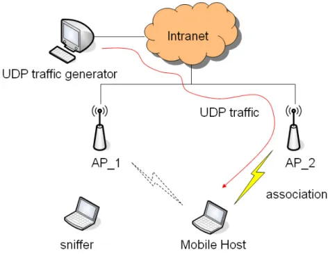
(15) III. EXPERIMENT FOR HANDOFF LATENCY MEASUREMENT In order to evaluate the latency and number of lost packet during handoff in IEEE 802.11 network, we use a linux desktop with an IEEE 802.11b network interface card (NIC) to simulate the MH and we control the NIC by linux-wlan-ng utility [16] to process active scan and association to simulate handoff procedure. For the purpose of analyzing the handoff latency and number of lost packet, an IBM laptop is used to be a sniffer to monitor and log the handoff procedure. Our experiment architecture is illustrated in Fig. 5 and the detailed specification of each device is listed in Table I.. Figure 5. Experiment architecture.. Table I. Detail specification of experiment environment. Mobile Host. x86 PC with Intel PIII 1GHz CUP OS: Linux Red hat 9 IP: 140.96.85.33. 9.
(16) NIC utility: linux-wlan-ng-0.2.0 UDP generator: Multi-Generator client Corresponding (UDP traffic generator) Node. x86 PC with Intel PIII 2GHz CUP OS: Windows XP IP: 140.96.85.48 UDP generator: Multi-Generator host. NIC. Z-COM 802.11b Model number: XI-303 Chipset: Intersil Prism 2.5 PCI interface Driver: prism2_pci.o with 0.2.0, 0.2.1-pre21 version. Sniffer. IBM T43 Laptop OS: Windows XP Sniffer program: NAI Sniffer Pro 4.7 NIC: Lucent Orinoco 802.11b. AP 1. Z-COM 802.11b Model number: Z-COM XI-1500E SSID: B3G_AP1 Channel 1: 2412MHz. AP 2. Z-COM 802.11b Model number: Z-COM XI-1500E SSID: B3G_AP2 Channel 6: 2437MHz. 10.
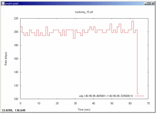
(17) For the purpose of simulating the traffic of real time application, a UDP generator program, Multi-Generator (MGEN) [17], is used. As shown in Fig. 5, we install MGEN, on corresponding node (CN) to generate UDP traffic by using the below script file:. 0.0 ON 1 UDP SRC 5001 DST 140.96.85.33/5000 PERIODIC [50 512] 60.0 OFF 1. The first line of script file instructs MGEN to generate 50 UDP packets per-second, each packet is 512 bytes. The data rate of the traffic is about 200kbps. The second line represents that the MGEN will generate the traffic for 60 seconds. In the peer, MH, we use MGEN client program to receive that UDP packets and log the result of reception. Then we use gnuplot program to figure the curve of data rate. The data rate is illustrated in Fig. 6.. 11.
(18) Figure 6. Data rate of simulating traffic generated by MGEN.. In order to simulate the handoff procedure, we control the NIC to respectively process active scan and association by linux-wlan-ng utility. First, we process the following command in linux console during the transmission of simulating traffic:. [root@sigda. network-scripts]#. wlanctl-ng. wlan0. dot11req_scan. bsstype=any. bssid=00:00:00:00:00:00. scantype=both probedelay=0 channellist="01:02:03:04:05:06:07:08:09:0a:0b:0c:0d:00" minchanneltime=200 maxchanneltime=1000 ssid=“”. The command orders NIC to process active scan with MinChannelTime = 20 ms and MaxChannelTime = 100 ms for 11 channels. After the NIC finishes active scan, it shows. 12.
(19) below result: message=dot11req_scan bsstype=any bssid=00:00:00:00:00:00 ssid='' scantype=both probedelay=0 channellist=01:02:03:04:05:06:07:08:09:0a:0b:0c:0d:00 minchanneltime=200 maxchanneltime=1000 resultcode=success numbss=2. According to the result of active scan, numbs = 2 indicates the NIC found 2 APs. Following the instruction above, we control the NIC to process handoff by following command in the linux console:. [root@sigda. network-scripts]#. wlanctl-ng. wlan0. lnxreq_autojoin. ssid=B3G_AP1. authtype=opensystem message=lnxreq_autojoin ssid='B3G_AP1' authtype=opensystem resultcode=success. The returned result shows the association was success and the NIC had finished handoff. 13.
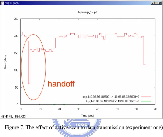
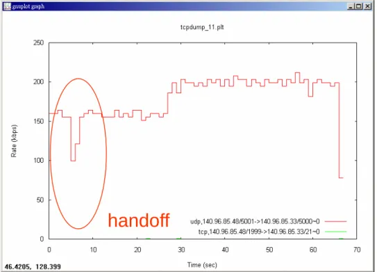
(20) procedure. Of course the handoff caused the broken of connection between the MH and the MH’s current AP. The handoff procedure affects the transmission of simulating traffic as show in Fig. 7 ~ 9.. handoff. Figure 7. The effect of active scan to data transmission (experiment one). 14.
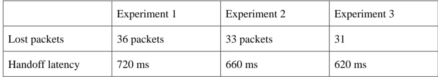
(21) handoff. Figure 8. The effect of active scan to data transmission (experiment two). handoff. Figure 9. The effect of active scan to data transmission (experiment three). By the experiments above, we record and analyze the handoff latency as listed in table II.. 15.
(22) Table II. The result of experiments Experiment 1. Experiment 2. Experiment 3. Lost packets. 36 packets. 33 packets. 31. Handoff latency. 720 ms. 660 ms. 620 ms. 16.
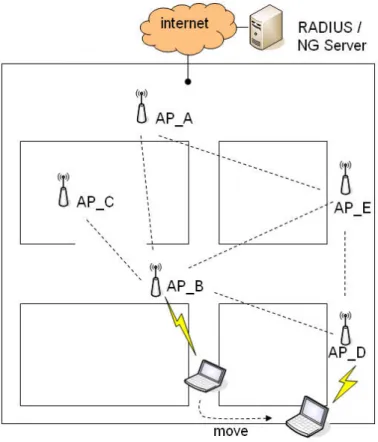
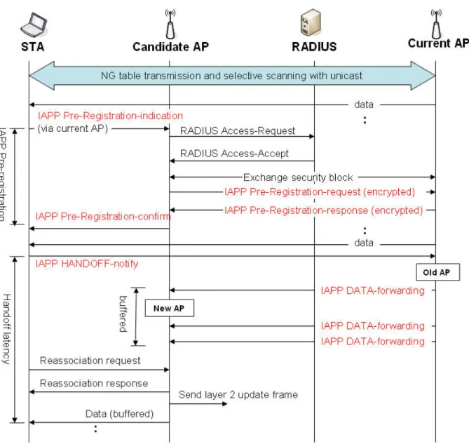
(23) IV. THE PROPOSED FAST AND SEAMLESS HANDOFF MECHANISM We propose a fast handoff mechanism by combining an enhanced neighbor graph scheme and an enhanced IAPP scheme. As mentioned earlier, the greater part of handoff latency is probe delay. If a MH knows exactly its adjacent APs, it can use selective scanning by unicast to avoid scanning all channels. Fig. 10 shows the system architecture. The dotted lines represent neighborhood relationship of APs. There is a NG Server in the IEEE 802.11 network. Every MH runs an application-level called NG Client responsible for exchanging NG information with the NG Server. The NG Server maintains a NG table, as shown in Table III. Each entry of the NG table indexed by the MH’s current AP contains 32 bytes of a neighbor SSID, 1byte of channel, 1 byte of loading, 4 bytes of IP address, and 6 bytes of BSSID. The NG table can be set manually or can be collected from roaming history of MHs (such as reassociation requests). The loading filed is an optional field to represent the number of MHs currently associated with an AP. It can be used to select a light-load AP. (The issue is irrelevant to the theme of this paper and is thus ignored below.) The original IAPP provides several functions to support host mobility, known as post-registration. However, there exists a period of handoff time, during which the MH cannot send/receive any frame to/from APs. These frames may be lost. Therefore, we propose a pre-registration mechanism for IAPP to reduce the handoff latency. To avoid losing frames, we propose a frame forwarding-and-buffering scheme. Six new IAPP packets are designed for this purpose. Fig. 11 shows the overall message flow in our handoff scheme. The state machine of the NG Client is illustrated in Fig. 12.. 17.
(24) Figure 10. The system architecture of our fast and seamless handoff mechanism.. Table III. NG table.. 18.
(25) Figure 11. The proposed pre-registration and forwarding-and-buffering mechanisms for IAPP.. 19.
(26) Figure 12. The state machine of NG Client. 1) When a MH associates with our network, its NG Client automatically connects to the NG Server to get the portion of the NG table indexed by its current AP. This gives the MH the neighbors near its current AP. These neighbors will be the target of the selective scanning procedure in step 2. Initially, the NG Client is in the idle state.. 2) Periodically, the MH will check the RSSI of its current AP. when the RSSI of its current AP is less than Thresholdscan, the NG Client will enter the selective scanning and pre-registration state. In this state, the MH will notify its current AP that it will enter the power-saving mode so that the AP can buffer incoming data for the MH. During this period, the MH will scan each all neighboring AP collected from step 1 by unicasting a probe request. The time that the MH should wait for a response from each AP is no more than MinChannelTime. If there is neither response nor traffic in that channel during MinChannelTime, the probe is regarded failure and the next AP is probed. This is known as selective scanning. After finishing scanning all APs, the MH will inform its current AP that it has returned to the active mode to receive data. 3) After returning to the active mode, the NG Client will send an IAPP Pre-Registration-indication packet to the candidate AP that has the best RSSI in step 2’s probing. 20.
(27) via its current AP. Upon receiving the IAPP Pre-Registration-indication packet, the candidate AP will send a RADIUS Access-Request packet to the RADIUS server to verify the current AP’s BSSID obtained from the received IAPP Pre-Registration-indication packet. If the current AP is legal, the RADIUS server will reply a RADIUS Access-Accept packet containing a security block for communication between the current AP and the candidate AP. On receiving the RADIUS Access-Accept packet, the candidate AP will exchange a security block with the current AP. After that, the candidate AP will send an encrypted IAPP Pre-Registration-request packet to the current AP to request the context information of the MH. In return, the current AP will reply an IAPP Pre-Registration-response packet which includes the MH’s context information. Then the candidate AP will respond an IAPP Pre-Registration-confirm packet to the MH. This completes the pre-registration procedure. Note that this would allow the candidate AP to accept an association request from the MH directly without further going through the probe procedure.. 4) When the RSSI of the current AP sensed is continuously decreasing and becomes less than Thresholdhandoff, the NG Client will make a handoff decision and enter the handoff state. The NG Client will then notify the current AP the fact by sending it an IAPP HANDOFF-notify packet containing the ID of the new AP. The current AP will break its association with the MH. Then the MH can directly reassociate with the new AP. Before the old AP receives the corresponding layer-2 update frame, all frames for the MH will still be routed to the old AP. These frames will be forwarded to the new AP by IAPP DATA-forwarding packets. Upon receiving these frames, the new AP will buffer these frames and deliver them to the MH after the MH (re)associates with the new AP. The NG Client will then return to the idle state.. 5) After the MH handoffs to the new AP, the NG Client will automatically connect to the. 21.
(28) NG Server to get the portion of the NG table related to its new AP. So it is prepared for the next handoff. Fig. 13 summarizes the handoff life cycle under the proposed scheme. Fig. 14 shows the change of signal strengths between two APs during handoff.. Figure 13. Handoff life cycle of our approach.. 22.
(29) Figure 14. Change of signal strengths during handoff.. 23.
(30) V. PERFORMANCE DISCUSSION In the section, we evaluate the performance of our approach. The typical handoff latency in an IEEE 802.11 with IAPP network can be expressed as thandoff = tscan + Tassociation + TIAPP. (2). Where tscan is the time for discovery phase and it can be a variable value with 40 ~ 300 ms. Tassociation is the time for exchanging association message between MH and AP. According to the result of experiment, it is about 2 ms. TIAPP represents the IAPP delay, it spend about 40 ms on exchanging MH’s context between the old AP and the new AP [5]. Totally, the average of thandoff is 212 ms. This would exceed the recommended latency of 50 ms in VoIP applications. For our approach, in contrast to (1), the MH exactly knows the number of neighboring APs and their occupational channel. So the MH has not to wait a MaxChannelTime period for discovery other potential APs. Its discovery latency can be written as tscan = MinChannelTime · Nch.. (3). According to [10], the optimum MinChannelTime is 1 TU (1024 μs), and here we believe that 3 ms should be sufficient. If a hexagonal cellular AP deployment is adopted, as illustrated in Fig. 15, then Nch is about 6, which means that tscan = 18 ms. Additionally, our selective scanning and pre-registration mechanisms are processed before layer-2 handoff. The selective scanning and pre-registration would not be the overhead during handoff, so we can eliminate the tscan and tIAPP parts. Thus, the handoff latency in our propose network is 2 ms. This should satisfy the timing constraint of most VoIP applications.. Figure. 15. The example of non-overlap channel assignment for IEEE 802.11b.. 24.
(31) VI. CONCLUSIONS In this paper, we have proposed a fast and seamless handoff mechanism for IEEE 802.11 network with IAPP. Many approaches have been proposed for the selection of the next AP or improvement of IAPP. In our approach, we tightly integrate the handoff procedure with the IAPP context-switching procedure. Most of the operations related to handoff are executed before handoff, including the selection of the next AP and the transfer of MH’s context. By switching a MH to the power-saving mode to process these operations, our mechanism actually achieves a certain degree of soft handoff. We have also proposed a frame forwarding-and-buffering mechanism to avoid losing data during handoff. The result is a reduction of 90% of handoff latency from typical procedure. It should be able to support most VoIP applications without problem.. 25.
(32) References [1] “Wireless LAN Medium Access Control (MAC) and Physical Layer (PHY) Specifications,” IEEE Standard, 1999. [2] Mishra, A Shin, and W. Arbaugh, “An Empirical Analysis of the IEEE 802.11 MAC Layer Handoff Process,” ACM SIGCOMM Computer Comm. Rev., vol. 33, no. 2, Apr. 2003. [3] International Telecommunication Union, “General Characteristics of International Telephone Connections and International Telephone Circuits,” ITU-TG.114, 1988. [4] H. Kim, S. Park, C. Park, J. Kim, and S. Ko, “Selective Channel Scanning for Fast Handoff in Wireless LAN using Neighbor Graph”, ITC-CSCC 2004, July 2004. [5] B. Aboba, “Fast handoff issues,” IEEE-03-155r0-I, IEEE 802.11 Working Group, Mar. 2003. [6] "IEEE Trial-Use Recommended Practice for Multi-Vendor Access Point Interoperability via an Inter-Access Point Protocol Across Distribution Systems Supporting IEEE 802.11 Operation", IEEE Standard, 2003. [7] “Wireless LAN Medium Access Control (MAC) and Physical Layer (PHY) specifications High-speed Physical Layer in the 5 GHz Band” IEEE Standard, 1999. [8] “Wireless LAN Medium Access Control (MAC) and Physical Layer (PHY) specifications: Higher-Speed Physical Layer Extension in the 2.4 GHz Band” IEEE Standard, 1999. [9] “Wireless LAN Medium Access Control (MAC) and Physical Layer (PHY) specifications Amendment 4: Further Higher Data Rate Extension in the 2.4 GHz Band” IEEE Standard, 2003. [10] Velayos, H. and G. Karlsson, "Techniques to Reduce IEEE 802.11b MAC Layer Handover Time", Laboratory for Communication Networks, KTH, Royal Institute of Technology, Stockholm, Sweden, TRITA-IMIT-LCN R 03:02, April 2003.. 26.
(33) [11] Kyoungnam Kwon and Chaewoo Lee , “A Fast Handoff Algorithm using Intelligent Channel Scan for IEEE 802.11 WLANs”, IEEE 6th International Conference, vol. 1, pp. 46- 50, 2004. [12] S. Shin, A. S. Rawat, H. Schulzrinne, "Reducing MAC Layer HandoffLatency in IEEE 802.11 Wireless LANs", ACM MobiWac'04, Oct, 2004. [13] C.C. Tseng, K.H. Chi, M.D. Hsieh, and H.H. Chang, “Location-based fast handoff for 802.11 networks”, IEEE Communications letters, vol. 9, issue 4, pp. 304- 306, April 2005. [14] C. Rigney et al., “Remote Authentication Dial In User Service (RADIUS),” RFC 2058, Jan. 1997. [15] C.T. Chou and K.G. Shin, “An Enhanced Inter-Access Point Protocol for Uniform Intra and Intersubnet Handoffs”, IEEE Transactions on Mobile Computer, vol. 4, no. 4, July/August 2005. [16] Linux-WLAN project, FL, USA, URL: http://www.linux-wlan.com/ [17] The Multi-Generator (MGEN) Toolset, Naval Research Laboratory http://manimac.itd.nrl.navy.mil/MGEN/ [18] J. Malinen, “Host AP Driver for Intersit Prism2/2.5/3,” http://hostap.epitest.fi/. 27. (NRL),.
(34)
數據
+7
相關文件
In this thesis, we have proposed a new and simple feedforward sampling time offset (STO) estimation scheme for an OFDM-based IEEE 802.11a WLAN that uses an interpolator to recover
“IEEE P1451.2 D2.01 IEEE Draft Standard for A Smart Transducer Interface for Sensors and Actuators - Transducer to Microprocessor Communication Protocols
F., “A neural network structure for vector quantizers”, IEEE International Sympoisum, Vol. et al., “Error surfaces for multi-layer perceptrons”, IEEE Transactions on
Krishnamachari and V.K Prasanna, “Energy-latency tradeoffs for data gathering in wireless sensor networks,” Twenty-third Annual Joint Conference of the IEEE Computer
D.Wilcox, “A hidden Markov model framework for video segmentation using audio and image features,” in Proceedings of the 1998 IEEE Internation Conference on Acoustics, Speech,
[16] Goto, M., “A Robust Predominant-F0 Estimation Method for Real-time Detection of Melody and Bass Lines in CD Recordings,” Proceedings of the 2000 IEEE International Conference
Hwang, “An O (nk)-time algorithm for computing the reliability of a circular consecutive-k-out-of-n:F system,” IEEE Trans on Reliability, Vol.. Shantikumar, “Recursive algorithm
在無線區域網路部份,高傳輸速度的要求,讓 IEEE 802.11a 成為矚目 的標準。本篇論文主要是以 FPGA 晶片來實現一適合於無限區域網路 IEEE 802.11a
