Dynamic Analysis of a Multimachine Small-Hydro Power System
Y.C. Wang , M.C. Lin and M.J. ChenDepartment of Electrical Engineering
National Kaohsiung University of Applied Sciences 415 Chien-Kung Rd., Kaohsiung 807, Taiwan, ROC
E-mail: [email protected]
Abstract
This paper presents the dynamic analysis of a multimachine small-hydro power system. Various mathematical models including hydraulic turbine prime mover model, induction generator model, electromechanical model, power factor correction capacitor bank model were employed to cater for the dynamic behavior of the system operating in load importing, load exporting, sequentially starting, and three-phase balanced fault situations. Simulation results showed that the system operated satisfactorily under those conditions. The dynamic study at preliminary planning stage is essential for a small-hydro project prior to construction.
Keywords : Dynamic Analysis, Multimachine, Small-Hydro, Induction Generator, Hydraulic Turbine
1. Introduction
In terms of installed capacity and energy yield, hydroelectric power is the foremost electricity-producing renewable energy technology in Europe and worldwide. In the EU, most of the sites suitable for large-scale schemes have already been developed and work therefore now concentrates on small-scale schemes [1-4].
The definition of small hydropower varies in different countries and can even include systems with a capacity of a few megawatts [5]. Small-scale hydro schemes are typically defined as having an installed capacity of less than 10MW/site [6-7]. A study by the Utility Data Institute, USA, predicts that a world total of 695 GW of new electricity capacity will come on line in the next ten years from all sources, 22% of which will be hydro, 26% gas, and 27% coal, with the remainder coming from a variety of sources. The world’s total technical feasible hydro potential is estimated at 14,000 TWh/year, of which about 8000 TWh/year is currently considered economically feasible for development. About 700 GW (or about 2600 TWh/year) is already in operation, with a further 108 GW under construction. Most of the remaining potential is in Africa, Asia and Latin America [8].
In developed countries, the demand for improved development of renewable energy sources is due to the need to reduce pollution and the greenhouse effect. A program of the European Commission aims to increase the role of renewable energy from 6% of raw energy consumption in
the European Union in 1995 to 12% in 2010 [9]. Programs such as this have been developed in many developed nations around the world [10,11]. In many of these countries increased hydropower production will only be possible through development of small-hydro potential, due to the fact that potential large hydro sites are either currently exploited or located in areas where development is undesirable.
In 1998, the Taiwanese government targeted the renewable energy contribution 10% to the national demand by 2020 [12,13]. In 2002, the total installed capacity of the utilities was 31.9 GW in which 17% was nuclear power, 21% was fuel steam power, 14% was fuel coal power, 14% was hydraulic power, and the rest was other resources. Small hydropower contributed 2.69% (120MW) to the hydraulic power.
This paper presents the dynamic analysis of a grid-connected multimachine small-hydro power system. The mathematical models including hydraulic turbine prime mover model, induction generator model, electromechanical model, power factor correction capacitor bank model are employed to cater for the dynamic behavior of the system operating under load importing, load exporting, starting sequentially, and three-phase balanced fault conditions. Simulation results showed that the system operated satisfactorily in those situations. The results of this study should aid in small-hydro power system planning and operation.
2. Methodology
2.1 System Configuration
The multimachine small-hydro power system includes three identical small-hydro plants (SHPs) that are connected in parallel with local load and then to the grid. Each of them consists of a 2.9 MVA, 69kV/3.3kV three-phase power transformer, a 2.5 MVA induction generator, and a power factor correction capacitor bank. Figure 1 shows the configuration of the system.
2.2 Electromechanical Models
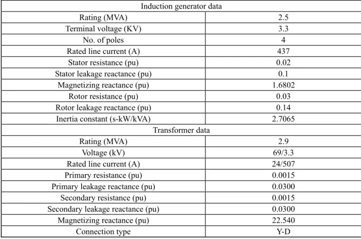
The electromechanical models of the system are developed using Power System Blockset (PSB). The parameters of the elements for the studies are given in Table 1.
Table 1 Principal data of the small-hydro power system
Induction generator data
Rating (MVA) 2.5
Terminal voltage (KV) 3.3
No. of poles 4
Rated line current (A) 437 Stator resistance (pu) 0.02 Stator leakage reactance (pu) 0.1
Magnetizing reactance (pu) 1.6802 Rotor resistance (pu) 0.03 Rotor leakage reactance (pu) 0.14 Inertia constant (s-kW/kVA) 2.7065
Transformer data
Rating (MVA) 2.9
Voltage (kV) 69/3.3
Rated line current (A) 24/507 Primary resistance (pu) 0.0015 Primary leakage reactance (pu) 0.0300 Secondary resistance (pu) 0.0015 Secondary leakage reactance (pu) 0.0300 Magnetizing reactance (pu) 22.540
Connection type Y-D
2.2.1.Induction Generator Model
Using induction motors as generators is a very cost effective way of providing a generator for a turbine system [14-16]. It especially works well with single-phase or three-phase systems that are interconnected to the utility for an induction system requires no governor controls. The induction motor, instead of consuming energy, is driven at some speed over its rated speed and the motor becomes a generator [17].
The electrical part of the machine is represented by a fourth-order state-space model, and the electromechanical part is expressed by a second-order model. All electrical variables and parameters are referred to the stator and all stator and rotor quantities are in the q-d frame.
The voltage equations, electromagnetic torque, and motion equation for the induction generator can be expressed as [18]
qs s qs qs ds d
V R i
dt
ϕ
ωϕ
ds s ds ds qs d V R i dt
ϕ
ωϕ
= + − (4) ' ' ' ' ( ) ' qr r qr qr r dr d V R i dtϕ
ω ω ϕ
= + + − (5) ' ' ' ' ( ) ' dr r dr dr r qr d V R i dtϕ
ω ω ϕ
= + − − (6) ( ) e ds qs qs ds 3 T p i i 2ϕ
ϕ
= − (7) ( ) m e m m d 1 T F T dtω
= 2H −ω
− (8)where φqs and φds are the stator q and d axis fluxes, φ’qr and φ’dr are the rotor q and d axis fluxes, p is the number of pole pairs, ωm is the angular velocity of the rotor, ωr is the electrical angular velocity, H is the combined rotor and load inertia constant, F is the combined rotor and load viscous friction coefficient.
2.2.2. Hydraulic Turbine Prime Mover Model
Within the category of small-hydro plant a wide range of turbine types are available [19]. The purpose of a hydraulic turbine is to transform the water potential energy to mechanical rotational energy. Francis turbines are radial flow reaction turbines with fixed runner blades and adjustable guide vanes used for medium heads. In the high speed Francis the admission is always radial but the outlet is axial. The diameter is selected as the result of a trade-off between penstock cost and power losses [20].
The power available from the flow Q and head H is given by the equation
avail
P =QHγ (7)
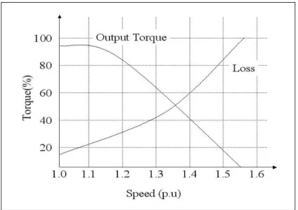
where Q is the discharge in m3/s, H the net head in m, γ the specific weight of water in kN/m3. Figure 2 shows the output torque versus speed for a mid-range unit when the input torque is a constant. The model of the turbine can be represented by a set of characteristic curves or functional blocks.
2.2.3 Power Factor Correction Capacitor
Power factor correction capacitors are sometimes added to the load bus or switched with the induction machines to provide a source of reactive power at the terminals of a motor or generator. The potential for self-excitation limits the amount of capacitance that may be switched with the induction machine to a value usually specified by the manufacturer.
Since induction generator operation is associated with lagging power factor, adding shunt capacitors for power factor correction is often desirable. The addition of capacitors to induction machines for power factor correction has been practiced for many years. An interlock device is installed at the terminal of induction generator and capacitor. While the induction generator is disconnected from the bus, the capacitors will also be disconnected from the bus. Therefore no self-excitation can occur.
Figure 2 Characteristics of the small-hydro turbine prime mover
3. Simulation and Discussion
3.1 System Operation
Operation of the induction generator is quite simple. The prime mover runs up first with the generator breaker open. When the generator has been brought up to slightly above synchronous speed, the generator breaker is closed to bring the unit on line. This procedure requires no great precision. Once on-line, the generator output is controlled by merely changing the speed of the prime mover.
3.2 Simulation Sequences
3.2.1 Simulation 1: Load importing and exporting (single set)
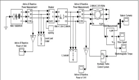
The induction machine was driven by the small hydraulic turbine to a speed close to synchronous speed. After 2 seconds power was added to drive it into generating region. At 4 second, more power was put into it. At 6 second, the power was reduced. Run time was 8 seconds. The PSB model for this simulation is shown in Figure 3. Simulation results are given in Figure 4a~4c.
3.2.2 Simulation 2: Sequentially starting (three sets)
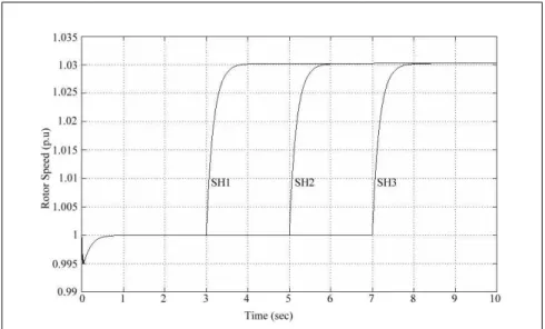
The first small hydro set started at 3 second, the second at 5 second, and the third at 7 second. Run time was 10 seconds. The PSB model for this simulation is shown in Figure 5. Simulation results are given in figure 6a~6c.
3.2.3 Simulation 3: Three-phase balanced fault (three sets)
Generators were connected to the grid and three-phase balanced fault was applied to transformer high-voltage side at 3 second. After 300 ms fault was cleared and induction generators were disconnected. Run time was 5 seconds. The PSB model for this simulation is shown in Figure 7. Simulation results are given in Figure 8a~8b.
3.3 Discussion of Results
In the simulation results, negative powers and torques implied that induction machines were in generating region.
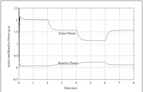
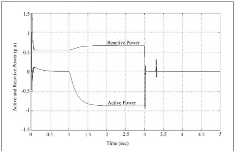
In simulation 1, the load importing and exporting simulation, the initial active power produced by the induction generator was zero. At 2 second, the active power was -0.45 pu (based on machine rating), then increased to -0.9 pu at 4 second, and decreased to -0.45 pu at 6 second, as shown in Figure 4a. Meanwhile, the speed of the generator was higher than 1.0 pu as shown in Figure 4b. The active power supplied by the grid reduced as the output power of the induction generator increased, and the active power supplied by the grid increased as the output power of the induction generator reduced, as shown in Figure 4c.
In simulation 2, the sequentially starting simulation, the generators started at 3, 5, and 7 second respectively. The active power produced by each generator was -0.9 pu as shown in Figure 6a. Meanwhile, the speed of each generator was higher than 1.0 pu as shown in Figure 6b. The power supplied by the grid reduced from 2 pu to -0.6 pu as the output power from the induction generators increased as shown in Figure 6c.
In simulation 3, the three-phase balanced fault simulation, the induction generators operated at steady state prior to fault occurrence at 3 second. Then they were disconnected, fault was cleared, and the grid bus voltage restored to normal 300 ms later. When fault occurred, transient appeared at the fault bus and SHP sets, as shown in Figure 8a and 8b.
4. Conclusions
This study analyzed the dynamic behavior of a multimachine small-hydro power system operating under load importing, exporting, starting sequentially, three-phase balanced fault conditions. Simulation results showed that the system operated satisfactorily under those conditions. It is in case of this type where the practical significance of machine system analysis is separated from purely theoretical work in that plant suitability and system design is assessed in relation to economic commitment. The dynamic study at preliminary planning stage is essential for a small hydro project prior to construction.
Figure 3 The PSB model for simulation 1
Figure 4a Active and reactive power of induction generator
Figure 4c Active and reactive power at grid bus
Figure 5 The PSB model for simulation 2
Figure 6b Rotor speeds of induction generators
Figure 6c Active and reactive power at grid bus
Figure 8a Active and reactive power of IG1
Figure 8b Active and reactive power at grid bus
References
[1] “Improving Market Penetration for Energy Technologies: Prospects for Pre-Competitive Support, Small Hydro Sector,” DGXVII, Oct. 1996.
[2] “Opportunities and Guidance for Foreign Investors in the Non-Conventional Energy Sector,” IN1 MNES/CII publication, Feb. 1996.
[3] “DTI Small Hydro Programme Area Review,” ETSU, Sept. 1995.
[4] “Renewable Energy Information List 2: Small Scale Hydropower,” ETSU, Feb. 1996 [5] Website, http:// www.microhydropower.net/
[6] Hermod Brekke, M., “Small Hydro-- Mechanical Equipment,” IEA Technical Report, March 2000.
[7] Kueny, J. L., “Objectives for small hydro technology,” IEA Technical Report, 1999 [8] Website, http://www.dams.org/
[9] Armand, F., “Assessment of Further Opportunities for R&D- Summary Report,” IEA Technical Report, March 2000.
[10] Allington, M., “Small Hydro Research and Development in Europe,” IEA Technical Report, 1998.
[11] Turner, A. B., R. J. Simpson, and C. Guillaud, “Developing a Mini-hydro Plant in the Remote Canadian North,” IEEE Transaction on Energy Conversion, Vol. 3 Issue 1, March 1988, pp. 18-25.
[12] Website, http://www.taipower.com.tw/ [13] Website, http://www.npf.org.tw/
[14] Ekanayake, J. B., “Induction Generators for Small Hydro Schemes,” Power Engineering
Journal, Vol. 16, Issue 2, 2002, pp. 61-67.
[15] Demetriades, G. M. “The Use of Induction Generators for Small-Scale Hydroelectric Schemes in Remote Areas,” Electrotechnical Conference, 10th Mediterranean, Vol. 3, 2000, pp. 1055-1058.
[16] Wallace, A. R., “Embedded Mini-Hydro Generation in the Water Supply Industry,” International Conference on Opportunities and Advances in International Electric Power Generation, (Conf. Publ. No. 419), 1996, pp. 168-171.
[17] Ong, C. M., “Dynamic Simulation of Electric Machinery using MATLAB/Simulink,” McGraw Hill Book Co., 1998.
[18] Power System Blockset For Use with Simulink® User’s Guide.
[19] “Layman's Guidebook on How to Develop a Small Hydro Site,” ESHA, May 1994.
[20] Harvey, A., A. Brown, P. Hettiarachi and A. Inversin, Micro-hydro design manual: A guide to small-scale water power schemes, 2000.