國立交通大學
電子物理研究所
博 士 論 文
脈衝式近紅外人眼安全雷射研究及探討
The Researches and Investigations of Pulsed
Laser in NIR Eye-safe Wavelength
研 究 生: 張漢龍
指導教授: 陳永富 教授
The Researches and Investigations of Pulsed Laser in NIR
Eye-safe Wavelength
研 究 生:張漢龍
Student:
Han-Lung
Chang
指導教授:陳永富 教授
Advisor: Prof. Yung-Fu Chen
國 立 交 通 大 學
電 子 物 理 研 究 所
博 士 論 文
A Dissertation
Submitted to Institute and Electrophysics College of Science
National Chiao Tung University In partial Fulfillment of the Requirements
for the Degree of Doctor of Philosophy
In
Electrophysics
June 2011
Hsinchu, Taiwan, Republic of China
脈衝式近紅外人眼安全雷射研究及探討
研究生: 張漢龍
指導老師:陳永富 教授
國立交通大學電子物理研究所博士班
中文摘要
脈衝式人眼安全雷射在醫療、通訊、遙測、以及雷射雷達、尋標、測距等軍事領域 上具有相當廣泛的應用。本文研究幾種產生人眼安全雷射的方式,一方面利用新穎的方 法提昇雷射轉換效率,另一方面針對不同應用面的需求,本論文研究幾種不同架構的脈 衝式人眼安全雷射的輸出特性。 (一)、利用腔內光參數共振腔技術產生數毫焦耳的高脈衝能量人眼安全雷射,並探 討被動式 Q 開關下的雷射閾值特性以及脈衝波形受到熱效應的影響所產生的變化; (二)、使用雙端擴散鍵合的自受激拉曼散射雷射晶體,Nd:YVO4,除本身具雷射增益產 生雷射之外,可自行產生受激拉曼散熱將波長轉換至 1525 奈米人眼安全雷射波段,並 且有效降低熱累積,使得轉換效率相對一般無擴散鍵合的受激拉曼散射晶體有效提昇 40%以上;(三)使用一雙包層之摻鉺/鐿離子大口徑光纖搭配新穎材料,鋁鎵銦砷量子井 半導體,來作為飽和吸收體產生 100 毫焦耳的高能量 1560 奈米人眼安全雷射,除優異 的散熱特性之外,更能保持高光束品質的輸出。(四)結合光纖雷射散射佳的特性、使用 一大口徑摻鐿光子光纖搭配鋁鎵銦砷量子井半導體高調制深度的優點,產生高脈衝能量 雷射,並使用週期性反轉鈮酸鋰晶體透過光參數共振腔產生一波長可調的人眼安全雷 射,波長調整範圍超過 80 奈米。(五) 使用鋁鎵銦砷量子井半導體當作雷射增益介質, 透過光激發的方式以及面射型的架構下產生一高光束品質的腔外面射型雷射,並且探討 由能障區激發及量子井區激發的輸出特性,在量子井區激發架構下,可有效降低熱的產 生,將整體轉換效率提昇到 30%以上。雷射輸出脈衝功率達 500 瓦。 藉由本論文對脈衝式近紅外人眼安全雷射的基礎研究及理論分析,我們可更進一步 掌握各架構的特性,並依此優化系統轉換效率及性能,進而滿足各應用面的需求。Eye-safe Wavelength
Student: Han-Lung Chang
Advisor: Prof. Yung-Fu Chen
Institute and Department of Electrophysics
National Chiao Tung University
ABSTRACT
Pulsed eye-safe lasers have drawn great interest since their wide potential in kinds of applications such as medical treatment, telecom communication, range-finder, and laser radar, etc. In this thesis, we study several schemes in realizing the NIR eye-safe lasers for different applications by employing novel materials and improving the conversion efficiency.
(a). In an intracavity optical parametric oscillator (OPO), a subnanosecond ten mJ eye-safe laser was demonstrated. We theoretically and experimentally investigated the threshold of an intracavity OPO pumped by a passively Q-switched laser and the dynamics of output pulse influenced by the thermal effect in the gain medium. (b). In the configuration of self stimulated Raman scattering (SRS), we employed a double-end diffusion-bonded Nd:YVO4 crystal to decrease the accumulated heat. The performance of the self-SRS laser at
1525 nm is found to be nearly 40% higher than that with a conventional Nd:YVO4 crystal. (c).
By employing an AlGaInAs semiconductor saturable absorber in a passively Q-switched Er/Yb codoped large-mode-area fiber laser, we demonstrated a passively Q-switched fiber laser at 1560 nm with output energy up to 100 μJ with high beam quality and good thermal management. (d) A passively Q-switched photonic crystal fiber (PCF) laser with an AlGaInAs saturable absorber was employed as pump source in an external-cavity OPO. By tuning the temperature of nonlinear crystal, periodically poled lithium niobate (PPLN), in the OPO, the tuning range of signal in eye-safe regime up to 80 nm was obtained. (e). An AlGaInAs QW/barrier was used as a gain medium in the external cavity surface emitting laser with high beam quality. The performance of barrier and in-well pumping schemes were investigated. The quantum defect is lower in in-well pumping and consequently the conversion efficiency is enhanced to 30% and a high peak output power up to 500 W was generated.
Based on these fundamental investigations in this thesis, we can know well the characteristics of these configurations of NIR pulsed eye-safe lasers and further expand the researches to meet kinds of applications.
誌 謝
Acknowledgement
『你知道我有多少次想像這一刻的到來?想好你和我坐在這裡,要說些什麼話。』 當電影"型男飛行日誌"中的主角達到一千萬飛行哩程的時候這麼對機長說著。我也曾這 樣想過,想好當這一刻來臨時,要如何對那些在這一路走來不斷給于我幫助以及精神上 鼓勵的前輩及朋友們寫出我心中的感謝。但不知道從什麼時候開始,我便不再覺得這一 刻是個終點,雖然在這一年來,歷經一連串的低潮及挫折的事件,似乎是要告訴我,想 要攻上這座山頭,就是要經歷這一番心智、精神、體力、以及情感上考驗,才足以在往 後的道路上直挺地走下去…。這,便是成長的過程。 非常感謝我的指導教授,陳永富老師這幾年來對我的栽培,陳老師是個有大智慧的 人,每次在與他的對談之中,總是能在他的隻字片語裡感受到對生命以及對生活上的熱 忱以及樂觀態度;在學術上,更是在信手拈來之間,便能發現研究的樂趣以及奧妙,叫 人讚佩。老師總是要我別想太多,凡事自有安排,但做事卻要有規劃,才能看得遠、有 效率;並且告訴我惟有提昇自己,才能走到哪裡都順遂。簡單扼要,卻受用無窮。 感謝黃凱風老師的指導,是個既和善又具有學術素養的老師,學識淵博,總是能在 簡短字語之間就能表達複雜的物理觀念。感謝閻偉中博士,一位既溫文儒雅、又熱心助 人的前輩跟主管。在我的博士研究生涯中,他總是不吝伸出他的手,毫無保留地提供他 的意見及資源協助我。對他我的心中總是有道不盡的感謝,卻一直無法當面說出口。 感謝周遭所有朋友們的大力支持,家銘、馬克、阿格西、戴博、還有其他同事,在 我情感最脆弱、工作最繁忙的時候,不斷地支援我、開導我,聽我說心事。感謝寵棟以 及碩泰,以前共患難的戰友,在畢業後仍不斷地協助我,在他們身上學到了許多對於人 生的態度。還有實驗室的學長姐以及學弟妹們,不形於色的老大、不拘小節的小黃、活 力四射的興弛、熱心義氣的哲彥、實驗快手依萍、講話如機槍的毅帆、個性溫和的威哲、 見解獨到的彥廷、心思細膩的毓捷、來自純樸東台灣的郁仁哥、行事低調的昆毅、對學 術充滿熱忱的舜子、實作超強的小江,還有三句話內就能帶動笑聲的易純,雖然我的年 紀要大上他們許多,但是與他們相處,總是讓自己感覺更年輕充滿了活力。謝謝善筑, 相處時間雖不長,但讓我對生活充滿新的期待。 在此,謹以此文,獻給我最摯愛的雙親及家人。感謝他們的教育之恩以及多年來不 帶任何壓力的支持、關懷以及鼓勵。中文摘要...i ABSTRACT...ii 誌謝...iii 目錄...iv 表目錄...vi 圖目錄...vi Chapter 1 Introduction ... 1 1.1 Motivation ...2
1.2 Optical Parametric Oscillator ...4
1.3 Stimulated Raman Scattering (SRS)...10
1.4 Erbium/Ytterbium Fiber Laser ...14
1.5 Optically-pumped Semiconductor Laser (OPSL)...19
1.6 Overview of this dissertation...26
Chapter 2 Passively Q-switched Eye-safe Laser with Optical Parametric Oscillator ....31
2.1 Intracavity OPO Pumped with Nd-doped Laser...32
2.2 Experimental setup ...33
2.2.1 Theoretical analysis of threshold...37
2.2.2 Experimental results and discussions ...40
2.3 The influence of birefringence on pulse behavior in OPO...44
2.3.1 Theoretical analysis and discussion in birefringence effect ...46
2.4 Conclusion ...53
Chapter 3 Self-Stimulated Raman Scattering Laser ... 56
3.1 Self-Stimulated Raman Scattering...57
3.2 Experimental setup ...59
3.3 Experimental results and discussions ...61
3.3.1 Thermal lensing effect in a 1342-nm cavity...61
3.4 Conclusion ...70
Chapter 4 Passively Q-switched Erbium/Ytterbium Fiber Laser...73
4.1 Semiconductor Saturable Absorber ...74
4.2 Experimental setup ...77
4.3 Results and discussions ...81
Chapter 5 Widely Tunable Eye-safe Laser with Photonic Crystal Fiber ... 89
5.1 Experimental setup and results ...92
5.1.1 Diode pumped PCF laser with AlGaInAs semiconductor absorber ...92
5.1.2 External-cavity OPO...99
5.2 Conclusion ...104
Chapter 6 Optically Pumped Semiconductor Laser... 108
6.1 OPSL with barrier-pumping ...109
6.1.1 Device fabrication and laser structure ...109
6.1.2 Experimental results and discussion... 113
6.2 OPSL with in-well-pumping...120
6.2.1 Device fabrication and experimental setup ...120
6.2.2 Experimental results and discussions ...126
6.3 Conclusion ...132
Chapter 7 Summary ... 135
7.1 Contribution of this dissertation ...136
Table 1.3-1. The parameters of commercial Raman crystals. ... 13 Table 5.1-1. The property of Yb doped rod-type PCF. ... 94
List of Figures
Chapter 1
Fig. 1.1-1. Transmission spectrum of human eyes [4]. The laser radiation after 1400 nm is absorbed by the ocular fluid of eyes and is called as eye-safe laser...3 Fig. 1.2-1. An incident field creates a source and then radiates an optical field. The
radiated filed would have higher order term [5]...5 Fig. 1.2-2. (a) Schematic of three-wave nonlinear process (b) Energy conservation
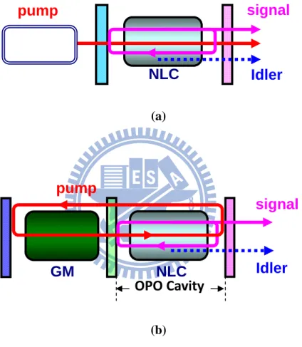
diagram of nonlinear process; (c) Momentum diagram under phase matching condition ...7 Fig. 1.2-3. The schematics of (a) External-cavtiy OPO; NLC: nonlinear crystal. (b)
Intra-cavity OPO; GM: gain medium. ...9 Fig. 1.3-1. The schematics of Stimulated Raman Scattering. ... 12 Fig. 1.4-1. (a) The absorption spectrum of Er3+ and codoped Er3+/Yb3+; (b)Energy level
diagram in codoped Er3+/Yb3+ fiber...15 Fig. 1.4-2. The schematic of double-cladding fiber. ... 17 Fig. 1.4-3. Different cladding design for increasing the pump absorption efficiency in
cores...18 Fig. 1.6-1. Schematic of typical VECSEL device ... 20 Fig. 1.6-2. (a) The lattice constant diagram of semiconductor compounds; (b) The
corresponding compounds versus radiated wavelength...21 Fig. 1.6-3. Quantum well arrangement: (a) Periodic structure of quantum wells. The
separation between successive pairs is designed to be half wavelength. (b) The quantum number as a function of the overlapping of optical intensity of lasing mode and pump mode [21]. ...23 Fig. 1.6-4. The method of thermal management: (a) Heat minimization by thinning the
device or bonding a transparent heat spreader [22]. (b) In-well pumping could have better thermal control than barrier pumping. ...24 Fig. 1.7-1. The overall structures of eye-safe lasers reported in this dissertation. ... 27
Chapter 2
Fig. 2.2-1. Experimental setup for an intracavity OPO pumped by a high-power QCW diode pumped passively Q-switched Nd:YAG laser in a shared resonator. ...34 Fig. 2.2-2. (a) The schematics of diode power coupled by a lens duct. (b) ~ (d) The
simulation result of intensity pattern in the image plane with 5-mm diameter from the exit surface of lens duct, 0.5 mm, 3 mm, and 5 mm respectively. The corresponding transmittance is 91.7 %, 87.9 %, and 68.4 %. ...35 Fig. 2.2-3. Calculated results for the dependence of the threshold photon density on the
output reflectivity Rs...39 Fig. 2.2-4. (a) Experimental results for the threshold pump energy versus the OPO output
reflectivity. (b) Experimental results for the pulse energy of the signal output versus the OPO output reflectivity ...41 Fig. 2.2-5. Experimental results for the temporal shapes of the fundamental and the
signal pulses...42 Fig. 2.2-6. Experimental results for the peak power of the signal output versus the OPO
output reflectivity...43 Fig. 2.3-1. The output temporal pulse at 1573 nm for different reflectivity of output
couple...45 Fig. 2.3-2. The schematic of depolarization due to thermally induced birefringence effect.
...48 Fig. 2.3-3. The temporal pulse of simulation result for the value of Γ = 0 and 0.03. The
result shows the influence of depolarization and the dependence of signal output reflectivity...51 Fig. 2.3-4. The output energy versus different output signal reflectivity. The solid lines
are numerical results of theoretical analysis for different value of Γ. The empty circles with error bar are experimental results...52
Chapter 3
Fig. 3.2-1. Experimental setup of (a) a diode-end-pumped actively Q-switched Nd:YVO4
Raman laser; (b) CW operation at 1342 nm for measuring thermal lens effect.60 Fig. 3.3-1. (a) The method for measuring the thermal lens by estimating the critical
cavity length in a 134-nm cavity. (b) Dependences of thermal lensing power on input pump power for conventional and double-end diffusion-bonded
Fig. 3.3-2. Optical spectrum of the diode-pumped actively Q-switch Nd:YVO4
self-Raman laser.z...65 Fig. 3.3-3. The average output power at 1525 nm with respect to the input pump power
at pulse repetition rates of 20 and 40 kHz shown as the down-triangle and circle symbols respectively for the double-end diffusion-bonded Nd:YVO4
crystal and that at 20 kHz shown as the square symbol for a conventional Nd:YVO4 crystal [1]. ...68
Fig. 3.3-4. Temporal characteristics of the fundamental and Raman pulses at a pulse repetition rate of (a) 40 kHz and (b) 20 kHz with a pump power of 17.2W. ....69
Chapter 4
Fig. 4.1-1. The energy diagram of (a) InGaAsP QWs/barriers; (b) AlGaInAs QWs/barriers...75 Fig. 4.2-1. Transmittance spectrum at room temperature for the AR-coated AlGaInAs/InP
SESA device. ...79 Fig. 4.2-2. Schematic of the experimental setup for EYDFL comprising a 7-m Er-Yb
codoped fiber and an external feedback cavity with a periodic AlGaInAs QW/barrier structure as a saturable absorber. HR, high reflection; HT, high transmission. ...80 Fig. 4.3-1. Dependence of the average output power on the incident pump power for the
cw and passive Q-switching operations...83 Fig. 4.3-2. Pulse repetition rate and the pulse energy versus the incident pump power. ... 84 Fig. 4.3-3. (a) Oscilloscope traces of a typical Q-switched envelope., (b) Oscilloscope
traces of a train of Q-switched pulses...85
Chapter 5
Fig. 5.1-1. The experimental setup of external-cavity pumped OPO with PCF fiber. ... 93 Fig. 5.1-2. (a) The image of cross section of rod-type PCF. (b) The transmission
spectrum and structure of AlGaInAs saturable absorber, which consists of 50 groups of three quantum wells...96 Fig. 5.1-3. The output power of the passively Q-switched PCF laser versus the 976-nm
pump power. ...97 Fig. 5.1-4. Typical oscilloscope traces of output pulses of the passively Q-switched PCF
laser. (a) Pulse shape with 6.3 W of pump power. (b) Pulse shape with 13.1 W of pump power. ...98 Fig. 5.1-5. The schematics of external-cavity OPO setup. A half-wave plate and
polarization beam splitter cube were settled in front of OPO to control the input pump power. ...100 Fig. 5.1-6. The output performance of external-cavity OPO. (a) The averaged output
power of signal wave versus averaged power of PCF laser. (b) The temporal traces of pump and signal wave...102 Fig. 5.1-7. The tuning curve of signal wavelength versus different operating temperature.
Inset, the conversion efficiency versus operating temperature...103
Chapter 6
Fig. 6.1-1. (a) Experimental configuration of the high-peak-power AlGaInAs QWs 1570-nm laser pumped by a Q-switched Nd:GdVO4 laser; HR: high
reflection, HT: high transmission, PR: partial reflection. (b)Actual setup. ... 111 Fig. 6.1-2. Room-temperature spontaneous emission spectrum of the AlGAInAs QWs
pumped by a Q-switched Nd:GdVO4 1064-nm laser... 112 Fig. 6.1-3. Experimental results for the optically pumped AlGaInAs 1570-nm laser
operated at the water temperature of 10°C at pump repetition rates of 20, 30, 40, and 60 kHz. Inset shows typical lasing spectrum obtained with 1.0 W of average pump power at a repetition rate of 30 kHz... 114 Fig. 6.1-4. Typical oscilloscope traces of pump and output pulse. ... 115 Fig. 6.1-5. (a) Experimental results for the peak output power versus peak pump power
at a repetition rate of 20 kHz; (b) the transmittance of the gain chip versus the excitation intensity at 1.57 μm... 118 Fig. 6.1-6. Input–output characteristics for the water temperatures of 10, 15, 20, and
25°C at a repetition rate of 30 kHz ... 119 Fig. 6.2-1. Schematic explanation of energy diagrams of (a) barrier pumping and (b)
in-well pumping...121 Fig. 6.2-2. The schematic of the AlGaInAs/InP eye-safe laser at 1555 nm. HR: high
structure. (b) the room-temperature spectrum of photoluminescence pumped by an actively Q-switched Nd:YVO4 1342-nm laser. (c) The single pass
absorption efficiency of single and double AlGaInAs QW chips...125 Fig. 6.2-4. The performance of single-chip AlGaInAs 1555-nm laser for 40 kHz and
12°C operation in the scheme of barrier and in-well pumping, respectively. The solid lines are forth order polynomial fitting curves. The in-well pumping scheme exhibits good performance in conversion efficiency...127 Fig. 6.2-5. Performance of double chips: (a) Experimental results for the optically
pumped AlGaInAs eye-safe laser operated at 12 °C for several pulse repetition rates. The repetition rate for optimum performance of conversion efficiency was between 40 kHz and 60 kHz. (b) Typical lasing spectrum at repetition rate of 40 kHz and average pump power of 0.65 W. ...128 Fig. 6.2-6. (a) The output characteristics of double chips in in-well pumping (50 kHz)
and of single chip in barrier pumping (30 kHz) were measured for the operation of different temperature. (b) The output peak power of double-chip in-well pumping AlGaInAs laser at the repetition rate of 20 kHz...130 Fig. 6.2-7. The typical pump and output pulse train and the expanded pulse shape of a
single pulse. ...131
Chapter 7
Fig. 7.2-1. (a) The concept of narrow-linewidth tunable eye-safe laser. (b) The simulated result of signal output wavelength pumped by tunable PCF laser...140
Chapter 1 Introduction
Chapter 1
1.1 Motivation
The motivation for this thesis started with the intention to develop a range finder with high pulse energy up to several mili-joules. The range between the target and the observer is obtained by measuring the time of flight of laser pulse. Most commercial products of range finder are with the wavelength around 1.5μm for the requirement of eye-safe regulations. The radiation around 1.5μm within eye-safe region is absorbed mainly in the ocular fluid of the eye before the retina such that the damage threshold of the eye is greatly increased (Fig. 1.1-1). With the increasing requirements in different applications and operating modes, for example, a hand-held range finder in the battle field requires high pulse energy with repetition rate in the 0.2~10 Hz level while a laser radar requires pulses with high repetition rate in the range of kHz to tens kHz. On the other hand, due to the fact that high-peak-power lasers operated at the eye-safe region near 1.5-1.6 μm have been attracting versatile interesting applications including telecom communication, 3D image, medical treatment, gas sensing, range-finder, designator, laser radar, and laser target [1]-[3], we expand the investigations to kinds of laser sources in different schemes.
In this thesis I report the present progress of my investigations and researches in realizing NIR eye-safe laser sources: (a) Optical parametric oscillators (OPO) pumped by high peak power neodymium (Nd) lasers operating at the 1064-nm line. (b) Self-stimulated Raman scattering (SRS) lasers pumped by pulsed Nd lasers operating at the 1340-nm lines. (c) Utilizing Erbium/Ytterbium (Er:Yb) ion-doped double cladding fiber as gain materials for generating 1.54-μm radiation. (d) A tunable laser with photonic crystal fiber (PCF). And (e) optically pumped semiconductor lasers with AlInGaAs Qw/barrier materials. Each method possesses different optical characteristics but one common issue that affects the performance is the thermal effect. The influence of thermal effect in those configurations will be taken care and the output performance will be investigated and discussed in the following chapters. In this dissertation, I will focus on the development of pulsed laser generation in NIR eye-safe region and on the investigations of the technology and physics.
Chapter 1 Introduction
Fig. 1.1-1. Transmission spectrum of human eyes [4]. The laser radiation after 1400 nm is absorbed by the ocular fluid of eyes and is called as eye-safe laser.
1.2 Optical Parametric Oscillator
When an electromagnetic field with angular frequencyω1 is incident on a dielectric
material, the dipoles inside the atoms react by starting to oscillate. Such an oscillation will radiate a new filed. Nonlinear wavelength conversion process is a result of higher order of dipole response (Fig. 1.2-1). Dipole response is frequency related but usually considered as linear with incident electric field under low intensity. If a nonlinear crystal, however, is illuminated with high intensity, the dipole response and then radiated light would contain higher order term which means the radiated field has higher order frequency.
(1) (2) 2 (3) 3 0 0 0 (1) (2) (3) Linear Nonlinear ( , ) ( , ) ( , ) ( , ) ( , ) ( , ) ( , ) P z t E z t E z t E z t P z t P z t P z t
ε χ
ε χ
ε χ
= + + + = + + + L L 14243 14444244443 (1-1)When the 2nd-order dipole response (P(2)( , )z t ) is considered, which means only three
waves are involved (Fig. 1.2-2(a)), the pump source with frequencyω1 can be regarded
providing gain via the nonlinear crystal to the other two radiated waves with frequency ω2
and ω3 (Fig. 1.2-2(b)). To finish the process, these three frequency components have to
satisfy energy conservation and momentum conservation:
1 2 3 1 2 3 k k k
ω ω ω
= + ⎧⎪ ⎨ = + ⎪⎩ur uur uur (1-2)Since materials are always dispersive, only under specific condition the above equations could be held simultaneously. That is,
1 2 3 1 1 2 2 3 3 1 2 3 1 1 1 2 2 2 ( ) ( ) ( ) n n n
λ
λ
λ
π
λ
π
λ
π
λ
λ
λ
λ
⎧ = + ⎪⎪ ⎨ ⎪ = + ⎪⎩ (1-3)Chapter 1 Introduction
Fig. 1.2-1. An incident field creates a source and then radiates an optical field. The radiated filed would have higher order term [5].
where λi is the corresponding wavelength and ni is the corresponding refractive index. We can derive the relationship of involved three electric fields, Eω1, Eω2, and Eω3, from Maxwell’s equations and obtain the following coupled wave equations of derivatives of fields along propagation direction,
1 1 2 3 0 1 2 * 2 1 3 0 2 3 * 3 1 2 0 3 eff j kz eff j kz eff j kz d E j E E e z c n d E j E E e z c n d E j E E e z c n ω ω ω ω ω ω ω ω ω ω ω ω ω ω ω Δ − Δ − Δ ⎧∂ = − ⎪ ∂ ⎪ ⎪∂ ⎪ = − ⎨ ∂ ⎪ ⎪∂ ⎪ = − ∂ ⎪⎩ (1-4)
where deff is the 2nd-order nonlinear coefficient of material, c0 light of speed, and
1 2 3
k kω kω kω
Δ =r r −r −r . When Δ =k kr rω1−krω2−krω3 =0 is termed as phase matching condition
and could be diagramed as Fig. 1.2-2(c).
From the coupled wave equations, we can see that if the phase matching condition is not satisfied (Δ ≠kr 0), the amplitude of field will oscillate with ejΔkz and can not grow up. On the contrary, when the condition is satisfied, the field will have an exponential gain under the situation of non-depleted pump source. Since the energy level between ω2 and ω3 is a
virtual level, we could design an appropriate condition to obtain output light with desired frequency and this nonlinear wavelength conversion process is referred to as optical parametric process.
If an additional oscillator is added to store energy of radiated waves in the parametric process, this is referred to as optical parametric oscillator (OPO). The first OPO was demonstrated in 1965 by Giordmaine and Miller and operated around 1 μm [6]. Depending on the choice of mirrors, different types of OPOs can be constructed. For example, it is possible to let one or two or three waves be resonated in the OPO, resulting in singly resonant (SRO), doubly resonant OPOs (DRO), or triply resonant OPOs (TRO). If one of the phases of three waves is fixed, for example, the phase of pump source in an external-cavity OPO
Chapter 1 Introduction
Fig. 1.2-2. (a) Schematic of three-wave nonlinear process (b) Energy conservation diagram of nonlinear process; (c) Momentum diagram under phase matching condition
1
k
2k
k
3 1ω
h
hω
2 3 ω hSignal
Idler
Pump NLC 1ω
h
h
ω
2 3ω
h
Filter (a) (b) (c)configuration, the alignment of a DRO cavity is more stringent than a SRO in order to simultaneously satisfy the phase matching condition and cavity phase. As a result, the most frequently used setup is the SRO, in which only the signal or idler is resonated.
Typically a wavelength-conversion system consists of a separated pump laser and an OPO configuration. This is referred to as external cavity OPO (Fig. 1.2-3(a)). An alternative configuration is the intracavity OPO, where the OPO is inserted into the laser cavity (Fig. 1.2-3(b)). In a nonlinear parametric process, the small-gain coefficient is proportional to laser intensity. Therefore, compared with the configuration of external cavity OPO, the intracavity OPO takes the advantage of higher laser intensity within the pump laser cavity to lower threshold and increase overall conversion efficiency.
At the present day, KTiOPO4 (KTP) and LiNbO3 (LN) are the most popular nonlinear
crystals used in optical parametric process in NIR region due to the advantages of high nonlinear coefficients, high damage thresholds, and broad transmission spectrum. To have more flexibility of tunable frequency and high conversion efficiency, the technique of quasi-phase matching in LN to be PPLN or in KTP to be PPKTP has been attracting lots of interest.
Chapter 1 Introduction
Fig. 1.2-3. The schematics of (a) External-cavtiy OPO; NLC: nonlinear crystal. (b) Intra-cavity OPO; GM: gain medium.
(a)
pump
signal
Idler
NLC
(b)OPO Cavity
signal
Idler
NLC
GM
pump
1.3 Stimulated Raman Scattering (SRS)
Unlike optical parametric process, Raman scattering is a 3rd-order nonlinear and inelastic scattering process where the incident light reacts with the vibrational mode of crystal lattice and losses energy or gets energy from the lattice. The first spontaneous scattering effect was first discovered by C. V. Raman in 1928. Raman scattering results in a frequency shift equal to phonon vibration frequency ωv and called as Raman shift. When the incident photon losses phonon energy, it is referred to as Stoke process and the photon becomes Stoke photon. On the contrary, it is referred to as anti-Stoke process if the incident photon obtains phonon energy. For both conditions, additional peak from pump incident photon in the spectrum will be observed.
Stimulated Raman scattering occurs when a stoke photon is incident together with a pump photon, the pump photon will transfer into another stoke photon and be stimulated to be coherent with the incident stoke photon (Fig. 1.3-1). Pump beam can be regarded to provide gain via the Raman crystal to the Stoke photons and amplify the incident photons. This can be achieved by introducing an oscillator to the Raman active medium. The mirrors of the oscillator are coated with high reflectivity or partial reflectivity in the frequency of the Stoke photons. The Stokes field will experience gain and if the Raman active medium is placed between two mirrors and the gain is strong enough to overcome the cavity’s losses, oscillation at Stokes frequencywill occur.
Though stimulated Raman scattering process is a 3rd-order nonlinear or four-wave mixing
process, there are only two photons involved, ωp and ωs. And the Raman shift does not depend on the pump laser wavelength, nor requires phase matching condition. Therefore, for generating eye-safe laser with SRS, only the pump source with proper wavelength and the Raman gain medium have to be considered. In order to provide enough gain, high pump intensity is required since the Raman gain is proportional to pump intensity. As intracavtiy OPO, an intracavity SRS also have the merits of decreasing the lasing threshold and increase the conversion efficiency.
Chapter 1 Introduction
Recently, the discovery of new Raman materials gives birth to the laser sources at new wavelengths. In the recent years, eye-safe lasers from SRS frequency conversion have been successfully demonstrated in several Raman materials such as Ba(NO3)2, YVO4, GdVO4,
SrWO4, KGWO4, BaWO4, and PbWO4 [7]-[12]. Some of the Raman materials and their
relative parameters are listed as Table 1.3-1. . Those materials are favored because they possess high Raman gain, high cross section, narrower linewidth, and high damage threshold. By incorporating the pump source and corresponding Raman gain medium, it is much practicable to realize an eye-safe laser. During those crystals, YVO4 or GdVO4 are attracting
more interest since they perform not just only as Raman crystals but also laser gain materials after doping with active ions such as neodymium (Nd). In the later chapter, I will discuss such materials can be used as both Raman crystals and laser gain materials simultaneously which is called as Self-SRS.
Fig. 1.3-1. The schematics of Stimulated Raman Scattering. p
ω
h
sω
h
pω
h hω
S Rω
h pω
h hω
S Rω
hChapter 1 Introduction
Table 1.3-1. The parameters of commercial Raman crystals.
Material Raman shift (cm-1) Raman linewidth (cm-1) Cross section (arb. Units) Raman gain (cm/GW) Damage threshold (GW/cm2) Ba(NO3)2 1047 0.4 21 11 ~ 0.4 BaWO4 924 1.6 52 8.5 ~ 5 KGd(WO4)2 768 901 6.7 5.7 59 54 4.4 3.3 ~ 10 YVO4 890 2.6 92 > 4.5 ~ 1 GdVO4 882 3 92 > 4.5 ~ 1 Material Raman shift (cm-1) Raman linewidth (cm-1) Cross section (arb. Units) Raman gain (cm/GW) Damage threshold (GW/cm2) Ba(NO3)2 1047 0.4 21 11 ~ 0.4 BaWO4 924 1.6 52 8.5 ~ 5 KGd(WO4)2 768 901 6.7 5.7 59 54 4.4 3.3 ~ 10 YVO4 890 2.6 92 > 4.5 ~ 1 GdVO4 882 3 92 > 4.5 ~ 1
1.4 Erbium/Ytterbium Fiber Laser
Fiber was firstly proposed to be doped with rare-earth elements such as erbium (Er), ytterbium (Yb), neodymium (Nd), praseodymium (Pr), and thulium (Tm), to be an active fiber since 1985. Such a fiber has been used to provide gain and amplify signal in a laser system. The doped element will decide the wavelength of fluorescence region. For eye-safe region, Nd3+ [13], Tm3+ [9] and Pr3+ [10] are mostly used to generate light source with high pulse energy and high peak power owing to their large cross section. Similar to bulk solid-state lasers, the gain fiber purely doped with Er3+ ions to lase at 1.54 μm has the problem of weak absorption. Therefore, doping with Yb3+ ions to sensitize Er3+ can greatly enhance the absorption at all room temperature since Yb3+ has a broad absorption from 0.9 to 1 μm (Fig. 1.4-1(a)). On the other hand, it can reduce the clustering of Er3+ ions, and allow for higher Er3+ concentrations without strong quenching effects. In the codoped Er/Yb fiber, radiation
from a laser diode pumps the strong 2F7/2–2F5/2 transition in Yb3+(Fig. 1.4-1(b)). The excited
Yb3+ ions transfer energy to the 4I11/2 level of Er3+ owing to the good overlap between the
upper states of Yb3+ and Er3+. The erbium ions then relax to the upper laser level 4I13/2 and
lasing occurs down to the 4I15/2 manifold.
A single mode fiber (SMF) is designed to follow the rule of V-number under the value of 2.405. That is,
(
2 2)
1 2 2 2 2.405 a a Vπ
n nπ
NAλ
λ
= − = < (1-5)where a is the core diameter, λ is the propagation wavelength, n1 and n2 are the refractive index of core, and cladding, respectively. NA demotes numerical aperture. Equation 1-5 shows that the single mode fiber has to be designed to keep the source into single mode signal. However, suffering from the high NA value of inner cladding, the skew rays of pump light enter the fiber off the fiber axis and zigzag down the fiber without crossing the axis. Those skew rays are regards as higher order modes guiding in the fiber. Those higher order modes possess poor mode overlapping with the core region of fiber such that the pump light can not
Chapter 1 Introduction
Fig. 1.4-1. (a) The absorption spectrum of Er3+ and codoped Er3+/Yb3+; (b)Energy level diagram in codoped Er3+/Yb3+ fiber.
(a) (b) Yb3+ 2F 5/2 2F 7/2 Er3+ 4FI 11/2 4FI 9/2 4FI 13/2 Energy transfer Pump 0.9~1 μm Lasing 1540 nm 4FI 15/2 Yb3+ 2F 5/2 2F 7/2 Er3+ 4FI 11/2 4FI 9/2 4FI 13/2 Energy transfer Pump 0.9~1 μm Lasing 1540 nm 4FI 15/2
be effectively absorbed. To overcome the limitation, consequently, a longer fiber length or an ingenious clad-design for higher absorption is needed to achieve an efficient fiber laser. Especially, a fiber with circular symmetry would have the worst coupling efficiency. As a result, there are a variety of designs of double-clad fibers to reduce symmetry of inner-cladding. For example, by designing the shape of core in an asymmetry type such as D-shape, rectangular shape, elliptic shape or petal structure (Fig. 1.4-3) the absorption efficiency can be greatly enhance up to 100 times than in a fiber with a symmetrically circular core shape.
Because of the merits of high spatial beam quality, low thermal lensing and their properties of beam confinement combined with excellent heat dissipation, double-clad fiber lasers are getting popular and competitive to conventional bulk solid-state lasers with regard to high-power applications.
Chapter 1 Introduction
Fig. 1.4-2. The schematic of double-cladding fiber.
Single-mode core (doped)
Outer cladding (polymer) Inner cladding (silica)
Refractive index Single-mode core
Inner cladding Outer cladding
Chapter 1 Introduction
1.5 Optically-pumped Semiconductor Laser (OPSL)
Vertical-external-cavity surface-emitting-laser (VECSEL), which is a small laser similar to vertical-cavity surface-emitting-laser (VCSEL) but without two high reflectors on the device, is grown with series of quantum wells to be an active layer incorporated with a Bragg reflector layer on semiconductor substrate (Fig. 1.5-1). The concept of using an external cavity enables integration of additional elements to improve the performance and flexibility in cavity design. Such a laser has the cavity axis along the direction of carrier flow instead of perpendicular to the flow as in conventional edge-emitting laser diodes and the radiation emerges from the surface of the cavity. Since the active region length is very short compared with the lateral dimensions, it is easier to obtain single longitudinal mode due larger mode spacing. On the other hand, unlike normal edge-emitting semiconductor laser, owing to the large emitting surface, it can generate a near diffraction-limited laser beam with single symmetrically transverse mode.
The quantum wells could be arranged in periodic or aperiodic way and covered by a window layer to prevent oxidation and surface recombination. These processes can be accomplished by MEMs techniques such as metal-organic chemical vapor deposition (MOCVD), or molecular beam epitaxy (MBE). The materials of quantum well/barrier and substrate are variety depending on the required wavelength. The composition of semiconductor compounds could be selected to from a new alloy from the engineered lattice constant diagram according to Vegard’s law (Fig. 1.5-2 (a)). In eye-safe region, GaInNAs/GaAs, InGaAsP/InP, and AlGaInAs/InP are popularly utilized [17]-[19] (Fig. 1.5-2 (b)) since high quality multilayer structures to be grown are allowed.
Optically pumped vertical-external-cavity surface-emitting-lasers (OP-VECSEL) belong to an emerging class of semiconductor lasers that combine high output power with a diffraction limited output beam. It is also referred to as OPSL. In parallel with the impressive characteristics of those electrically-driven devices, the advantages of OPSL compared with electrically-driven semiconductor laser are the availability of uniform and high-power
Fig. 1.5-1. Schematic of typical VECSEL device Substrate Bragg reflector
Active layer Pump
Chapter 1 Introduction
Fig. 1.5-2. (a) The lattice constant diagram of semiconductor compounds; (b) The corresponding compounds versus radiated wavelength.
Lattice constant (A)
(b) (a) 200 400 600 800 1000 1200 1550 1400 1600 GaInNAs/GaAs GaAsSb/GaAs InGaAs/GaAs AlGaAs/GaAs AlGaInP/GaAs GaInN/GaN nm InGaAsP/InP AlGaInAs/InP
pumping as well as larger cavity mode size. This result in a good mode matching and single transverse mode with high output power, wavelength controllable and fast dynamics.
Since quantum wells in the active layer offers gain and they are laid onto the wafer during the growth process, their thickness and position in the structure can be optimized. Quantum wells are stacked perpendicular to the optical propagation axis and spaced by barriers. The fluorescence radiated from each quantum well is feed back bye the oscillator and resonates in the cavity. In order to obtain resonant periodic gain, the quantum wells are usually centrally designed to be located at the antinodes of the lasing mode of the micro-cavity standing wave, or to have intervals of half-wavelength separated by barriers [19], [20]. Hence, gain locates where it is most accessible and only where it is required thus eliminating saturation effects and spatial hole burning. The technique was used to improve the efficiency of surface emitting lasers and is known as Resonant Periodic Gain (RPG). In addition to a periodic structure, more complex structure has ever been proposed with dynamic number of quantum wells to have good overlapping of intensity between pumping mode and lasing mode simultaneously [21].
Typically, the structure of VCESEL contains several parts: The gain region containing quantum wells, distributed Bragg reflector (DBR), and substrate. Regarding a single-mode OPSL, the output power is inhibited by induced thermal and usually limited to some milli-watts. The main sources of heat generation are from the active region, DBR, and substrate. For high power operation of OPSL, the efficient thermal management or heat removal has become an issue and has to be treated considerately. Conventionally, there are two methods to minimize the temperature rise of VECSEL. One is to reduce the heat generation from the internal structure of VCESEL. This could be achieved by thinning the thickness of DBR and substrate [22]. Moreover, the DBR could be eliminated and replaced by an external cavity. The other one is thermal removal by bonding a transparent thermally conductive dielectric material or adhering a heat sink such as copper or diamond to the device. Such a materials act as heat spreaders.
Chapter 1 Introduction
Fig. 1.5-3. Quantum well arrangement: (a) Periodic structure of quantum wells. The separation between successive pairs is designed to be half wavelength. (b) The quantum number as a function of the overlapping of optical intensity of lasing mode and pump mode [21].
2
λ
(b) (a)
Fig. 1.5-4. The method of thermal management: (a) Heat minimization by thinning the device or bonding a transparent heat spreader [22]. (b) In-well pumping could have better thermal control than barrier pumping.
(a) (b) 1555 nm 1555 nm 1064 nm QW barrier QW barrier 1064 nm
Chapter 1 Introduction
The main heat source comes from the quantum deficit, the energy difference between a pump and a laser photon, in the active region. The required pumping energy from ground state to excited state for carriers is lower in the quantum well than in the barrier region. Therefore, in addition to the thermal alleviation from DBR and substrate, the heat could be also reduced from the active region by in-well pumping rather than barrier pumping [23]-[25].
1.6 Overview of this dissertation
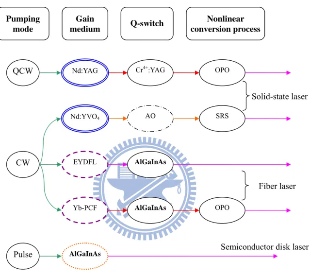
The accomplishments of this dissertation are the novel investigations in the realization of eye-safe lasers and the thermal management to improve the performance. The overall structures of the eye-safe lasers in this dissertation are summarized in Fig. 1.6-1. The organization of this dissertation is mainly as follows. Chapter 2 describes a high-pulse-energy eye safe laser up to ten mJ in the repetition rate of 1 ~ 20 Hz via optical parametric oscillator and the investigation of pulse dynamics under the thermally induce birefringence effect. Chapter 3 shows an idea of diffusion-bond Raman crystal employed in the slef-SRS to improve the thermal effect and then the performance. Chapter 4 shows a passively Q-switched Er/Yb doped double cladding fiber laser with a novel AlGaInAs quantum well structure to be a saturable absorber. Chapter 5 describes a widely tunable laser accomplished with an OPO pumped by a passively Q-switched PCF laser with AlGaInAs quantum well structure to be a saturable absorber. Chapter 6 shows high-power AlGaInAs OPSLs with barrier pumping and in-well pumping and the investigations of thermal management via different pumping scheme. Chapter 7, I list the contributions of this dissertation and the future work in the following researches.
Based on the gain mediums, there are three categories in laser types: solid-state lasers, fiber lasers, and vertical external cavity surface emitting laser (semiconductor disk laser). Three pumping modes: continues-wave (CW), quasi-continuous-wave (QCW), and pulsed mode. The lasers are Q-switched in two ways to generate short pulse: passively and actively (Acoustic optical, AO). For the passively Q-switching, Cr4+:YAG and AlGaInAs QW/barrier are used as saturable absorblers. The overall structures of pulsed eye-safe laser reported in this dissertation are summarized in Fig. 1.6-1.
Chapter 1 Introduction
Fig. 1.6-1. The overall structures of eye-safe lasers reported in this dissertation. Pulse CW QCW Pumping mode Gain medium Q-switch Nonlinear conversion process AlGaInAs Yb-PCF EYDFL Nd:YVO4 Nd:YAG AlGaInAs Cr4+:YAG OPO SRS OPO AlGaInAs AO Solid-state laser Fiber laser
References
[1]. S. M. Spuler and S. D. Mayer, “Raman shifter optimized for lidar at a 1.5 µm wavelength,” Appl. Opt. 46, 2990-2995 (2007).
[2]. G. S. Mecherle, Ed., Free-Space Laser Communication Technologies XIII, San Jose, CA, 24 to 25 January 2001, Proc. SPIE 4272 (2001).
[3]. A. J. McGrath, J. Munch, G. Smith, and P. Veitch, “Injection-Seeded, Single-Frequency, Q-Switched Erbium:Glass Laser for Remote Sensing,” Appl. Opt. 37, 5706-5709 (1998).
[4]. http://www.microscopyu.com/print/articles/fluorescence/lasersafety-print.html [5]. Bahaa E. A. Saleh, Malvin Carl Teich, “Fundamentals of photonics”, Chap 19, John
Wiley & Sons, New York (2001).
[6]. J. A. Giordmaine and R. C. Miller, “Tunable Coherent Parametric Oscillation in LiNbO3
at Optical Frequencies,” Phys. Rev. Lett. 14, 973 (1965)
[7]. G. M. A. Gad, H. J. Eichler, and A. A. Kaminskii, “Highly efficient 1.3-μm second-Stokes PbWO4 Raman laser,” Opt. Lett. 28, 426-428 (2003).
[8]. A. A. Kaminskii, K. Ueda, H. J. Eichler, Y. Kuwano, H. Kouta, S. N. Bagaev, T. H. Chyba, J. C. Barnes, G.M. A. Gad, T. Murai, and J. Lu, “Tetragonal vanadates YVO4
and GdVO4 – new efficient χ(3)-materials for Raman lasers,” Opt. Commun. 194,
201-206 (2001).
[9]. S. H. Ding, X. Y. Zhang, Q. P. Wang, F. F. Su, P. Jia, S. T. Li, S. Z. Fan, J. Chang, S. S. Zhang, and Z. J. Liu, “Theoretical and experimental study on the self-Raman laser with Nd:YVO4 crystal,” IEEE J. Quantum Electron., 42, 927-933 (2006).
[10]. Y. F. Chen, “High-power diode-pumped actively Q-switched Nd:YVO4 self-Raman
laser: influence of dopant concentration,” Opt. Lett., 29, 1915-1917 (2004).
[11]. F. F. Su, X. Y. Zhang, Q. P. Wang, S. H. Ding, P. Jia, S. T. Li, S. Z. Fan, C. Zhang, and B. Liu “Diode pumped actively Q-switched Nd:YVO4 self-Raman laser,” J. Phys. D: Appl.
Chapter 1 Introduction
[12]. F. Hanson, “Improved laser performance at 946 and 473 nm from a composite Nd:Y3Al5O12 rod,” Appl. Phys. Lett., 66, 3549-3551 (1995).
[13]. Etienne Rochat, Karim Haround, and René Dändliker, “High-power Nd-doped fiber amplifier for coherent intersatellite links,” IEEE J. Quantum Electron., 35, 1419-1423 (1999).
[14]. Tadashi Sakamoto, Makoto Shimizu, Makoto Yamada, Terutoshi Kanamori, Yasutake Ohishi, Yukio Terunuma, and Shoichi Sudo, “35-dB gain Tm-doped ZBLYAN fiber amplifier operating at 1.65 μm,” IEEE Photon. Technol. Lett., 8, 349-351 (1996).
[15]. Makoto Yamada, Terutoshi Kanamori, Yasutake Ohishi, Makoto Shimizu, Yukio Terunuma, and Shoichi Sudo, “Pr3+-doped fluoride fiber amplifier module pumped by afiber coupled master oscillator/power amplifier laser diode,” IEEE Photon. Technol. Lett., 9, 321-323 (1997)
[16]. E.Snitzer et al., “Double-clad, offset-core Nd fiber laser,” proc.conf. Optical fiber Sensors, Postdeadline paser PD5 (1988).
[17]. C. E. Zah, R. Bhat, B. N. Pathak, F. Favire, W. Lin, M. C. Wang, N. C. Andreadakis, D. M. Hwang, M. A. Koza, T. P. Lee, Z. Wang, D. Darby. Flanders, and J. J. Hsieh, “High-performance uncooled 1.3-m AlGaInAs/InP strained-layer quantum-well lasers for subscriberloop applications,” IEEE J. Quantum Electron. 30, 511–521 (1994).
[18]. J. Minch, S. H. Park, J. Minch, and S. L. Chuang, “Theory and Experiment of InGaAsP and InGaAlAs long-wavelength strained quantum-well lasers,” IEEE J. Quantum Electron. 35, 771-782 (1999)
[19]. M. Y. A. Raja, S. R. J. Brueck, M. O. Scully, C. Lee, “Resonant Periodic Gain Surface-Emitting Semiconductor Lasers,” Phys. Rev. A. 44, 4599-4607 (1991).
[20]. S. W. Corzine, R. S. Geels, J. W. Scott, R. H. Yan, L. A. Coldran, “Design of Fabry-Perot Surface-Emitting Lasers with a Periodic Gain Structure,” IEEE Quantum Electronics. 25, 1513-1524 (1989).
[21]. N. Schulz, M. Rattunde, et.al., “Resonant optical in-well pumping of an (AlGaIn)(AsSb)-based vetical-external-cavity surface-emitting laser emitting at 2.35 um”, Appl. Phys. Lett. 91, 091113 (2007)
[22]. J.M. Hopkins, S. Calvez, A. J. Kemp, J. E. Hastie, et al., “High-power vertical external-cavity surface-emitting lasers,” Phys. Stat. Sol. 3, No. 3, 308-385 (2006)
[23]. M. Schmid, S. Benchabane, F. T. Goudarzi, R. Abram, A. I. Ferguson, and E. Riis, “Optical in-well pumping of a vertical-external-cavity surface-emitting laser,” Appl. Phys. Lett. 84, 4860-4862 (2004)
[24]. J. Wagner, N. Schulz, M. Rattunde, C. Ritzenthaler, C. Manz, C. Wild, and K. Köhler, “Barrier- and in-well pumped GaSb-based 2.3 μm VECSELs,” Phys. Status Solidi 4, No 5, 1594-1600 (2007).
[25]. H. L. Chang, S. C. Huang, Yi-Fan Chen, K. W. Su, Y. F. Chen, and K. F. Huang, "Efficient high-peak-power AlGaInAs eye-safe wavelength disk laser with optical in-well pumping," Opt. Express 17, 11409-11414 (2009).
Chapter 2 Passively Q-switched Eye-safe Laser with Optical Parametric Oscillator
Chapter 2
Passively Q-switched Eye-safe Laser
with Optical Parametric Oscillator
2.1 Intracavity OPO Pumped with Nd-doped Laser
Intracavity optical parametric oscillator (OPO) is one of the most promising approaches for high-peak-power eye-safe laser sources since it can greatly reduce the lasing threshold due to the high pump intensity in the cavity. The advent of high damage threshold nonlinear crystals and diode-pumped Nd-doped lasers leads to a renaissance of interest in intracavity OPO’s. In recent years, a number of efficient eye-safe intracavity OPOs pumped by actively [1]-[3] or passively [4]-[6] Q-switched Nd-doped lasers have been demonstrated to produce pulse energies of tens of μJ with pulse peak powers of 1-100 kW.
The intracavity OPOs are mostly constructed with the coupled cavity configuration in which the resonators for the signal and fundamental wave fields are separate. Recently, it was found [7], [8] that the shared cavity configuration in which the pump and signal beams share the same resonator provides a substantially superior amplitude stability, in comparison with the coupled cavity configuration. Even so, the maximum peak power in a shared cavity is usually several times lower than that in a coupled cavity under the circumstance of the same output coupler. Therefore, it is a practical interest to explore an intracavity OPO in a shared resonator in quest of optimal pulse energies and peak powers.
In this chapter, I will report a ten-mJ eye-safe laser with an intracavity OPO pumped in a shared resonator. We first confirm that the threshold of an intracavity OPO pumped by a passively Q-switched laser is essentially determined by the bleach of the saturable absorber not by the signal output reflectivity. On the other hand, we numerically analyze and experimentally demonstrate the pulse behavior is affected by the birefringence induced from thermal effect in active medium.
Chapter 2 Passively Q-switched Eye-safe Laser with Optical Parametric Oscillator
2.2 Experimental setup
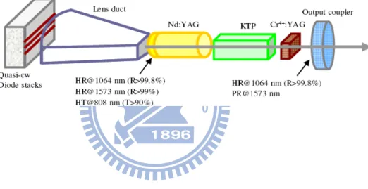
Figure 2.2-1 shows the experimental setup for an intracavity OPO pumped by a high-power quasi-continuous-wave (QCW) diode-pumped passively Q-switched Nd:YAG laser in a shared resonator. The fundamental laser cavity was formed by a coated Nd:YAG crystal and an output coupler. The OPO cavity entirely overlapped with the fundamental laser cavity. The pump source is a high-power QCW diode stack (Quantel Laser Diodes) that consists of three 10-mm-long diode bars generating 130 W per bar, for a total of 390 W at the central wavelength of 808 nm. The diode stack is designed with 0.4 mm spacing between the diode bars so the overall area of emission is approximately 10 mm (slow axis) × 0.8 mm (fast axis). The full divergence angles in the fast and slow axes are approximately 35° and 10°, respectively. A lens duct was exploited to couple the pump light from the diode stack into the laser crystal. The lens duct has the benefits of simple structure, high coupling efficiency, and unaffected by slight misalignment. The geometric parameters of a lens duct include r, L, H1,
H2, and H3, where r is the radius of the input surface, L is the length of the duct, H1 is the
width of the input surface, H2 is the width of the output surface, and H3 is the thickness of the
duct [9], [10]. Here a lens duct with the parameters of r = 10 mm, L = 32 mm, H1 = 12 mm,
H2 = 2.7 mm, and H3 = 2.7 mm was manufactured and used in the experiment. The coupling
effect and the intensity distribution of intensity in exit surface of lens duct was simulated with commercial optical engineering software, the Advanced Systems Analysis Program (ASAP), as depicted in Fig. 2.2-2. The coupling efficiency of this lens duct was measured to be approximately 90 % and is in good agreement with simulation results.
Fig. 2.2-1. Experimental setup for an intracavity OPO pumped by a high-power QCW diode pumped passively Q-switched Nd:YAG laser in a shared resonator.
Chapter 2 Passively Q-switched Eye-safe Laser with Optical Parametric Oscillator
Fig. 2.2-2. (a) The schematics of diode power coupled by a lens duct. (b) ~ (d) The simulation result of intensity pattern in the image plane with 5-mm diameter from the exit surface of lens duct, 0.5 mm, 3 mm, and 5 mm respectively. The corresponding transmittance is 91.7 %, 87.9 %, and 68.4 %. d=0.5 mm d=3 mm d=5 mm (a) (b) (c) (d) Image plane Lens duct Diodes d
The gain medium was a 1.0 at. % Nd:YAG crystal with a diameter of 5 mm and a length of 10 mm. The incident surface of the laser crystal was coated to be highly reflective at 1064 nm and 1573 nm (R>99.8%) and highly transmitted at the pump wavelength of 808 nm (T>90%). The other surface of the laser crystal was coated to be antireflective at 1064 nm and 1573 nm (R<0.2%). The nonlinear material for the intracavity OPO was an x-cut KTP crystal with a size of 4×4×20 mm3. The saturable absorber for the passive Q-switching was a Cr4+:YAG crystal with a thickness of 3 mm and an initial transmission of 60% at 1064 nm. Both surfaces of the KTP and Cr4+:YAG crystals were coated for antireflection at 1573 nm and 1064 nm. All crystals were wrapped with indium foil and mounted in conductively cooled copper blocks. The output coupler had a dichroic coating that was highly reflective at 1064 nm (R > 99.8%) and partially reflective at 1573 nm. Several output couplers with different reflectivities (10% ≤ Rs ≤ 70%) at 1573 nm were used in the experiment to investigate the output optimization. The total cavity length was approximately 5.5 cm. The pulse temporal behavior at 1063 nm and 1571 nm was recorded by a LeCroy digital oscilloscope (Wavepro 7100; 10 G samples/sec; 1 GHz bandwidth) with a fast InGaAs photodiode. The spectral information was monitored by an optical spectrum analyzer (Advantest Q8381A) that employs a diffraction grating monochromator to for measure high speed light pulses with the resolution of 0.1 nm. In all investigations, the diode stack was driven to emit optical pulses 250 μs long, at a repetition rate less than 40 Hz, with a maximum duty cycle of 1%.
Chapter 2 Passively Q-switched Eye-safe Laser with Optical Parametric Oscillator
2.2.1 Theoretical analysis of threshold
The advantage of the intracavity OPO mainly consists in the exploit of high photon density of the fundamental wave. First of all, we analyze the maximum value of the intracavity photon density for the fundamental wave in a passively Q-switched laser. Next, we verify that the intracavity photon density of the present laser cavity can generally exceed the threshold of a singly resonant intracavity OPO by far, even though the reflectivity of the output mirror at the signal wavelength is nearly zero. In a passively Q-switched laser with a fast Q-switching condition, the maximum value of the intracavity photon density of the fundamental wave can be expressed as [11]
,max 1 φ = ⎧⎪⎨ − ⎡⎢ +⎛ ⎞⎜ ⎟⎤⎥⎫⎪⎬ ⎢ ⎝ ⎠⎥ ⎪ ⎣ ⎦⎪ ⎩ ⎭ gm i f i t cav t l n n n l n (2.1-1) where
(
2)
(
)
0 1 ln 1/ ln 1/ 2σ ⎡ ⎤ = ⎣ + + ⎦ i gm n T R L l ;(
)
(
)
2 0 1 ln 1/ ln 1/ 2σ ⎡β ⎤ = ⎣ + + ⎦ t gm n T R L l ; σ β σ = es gs ; n is ithe initial population density in the gain medium; σ is the stimulated emission cross section of the gain medium; lgm is the length of the gain medium; lcav is the cavity length; To is the initial transmission of the saturable absorber; σgs and σes are the ground-state and excited state absorption cross sections in the saturable absorber, respectively; R is the reflectivity of the output mirror at the fundamental wavelength; and L is the nonsaturable intracavity roundtrip loss. With the properties of the Nd:YAG and Cr4+:YAG crystals and the typical cavity parameters: σ= 2.8×10⁻¹⁹ cm2 , σgs = 8.7×10⁻¹⁹ cm2, σes = 2.2×10⁻¹⁹ cm2, lcav = 5.5 cm, R = 99.8%, To = 0.6, and L = 0.01, it can be found that φf,max can be up to 1.56×1017 cm-3.
With Brosnan and Byer’s equation [12], the threshold photon density for the double-pass pumped, single resonant OPO is derived to be given by
2 , 2 1.12 1 ( ) 33 ln ln 4 (1 ) φ γ τ ⎡ ⎛ ⎞ ⎤ = ⎢ + ⎜⎜ ⎟⎟+ + ⎥ + ⎢⎣ ⎝ ⎠ ⎥⎦ cav f th s s s p s l R L Gg c R (2.1-2)
2 2 1 2 3 2 1 2 3 0 2 ω ω ω ε = h d leff nl G n n n c (2.1-3)
where gs is the mode coupling coefficient, γ is the ratio of backward to forward pump amplitude in the cavity; ω1, ω2 and ω3 are the signal, idler and pump frequencies, respectively;
n2 and n3 are the refractive indices at the signal, idler and pump wavelengths, respectively; τp is the FWHM of the pump pulse; deff is the effective non-linear coefficient; ε0 is the vacuum permittivity; c is the speed of light; lnl is the length of the nonlinear crystal; Ls is the round-trip signal wave intensity loss in the cavity; and Rs is the output reflectivity at the signal
wavelength.
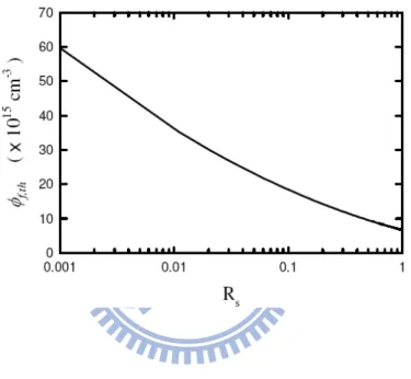
Figure 2.2-3 depicts the calculated results for the dependence of the threshold photon density φf th, ( )Rs on the output reflectivity Rs with the properties of the KTP crystal and the typical cavity parameters: ω1 = 1.198×10¹⁵ sec-1, ω2 = 5.712×10¹⁴ sec-1, ω3 = 1.865×10⁻¹⁹ J,
deff = 3.64 pm/V, lnl = 20 cm, n1 = 1.737, n2 = 1.771, n3 = 1.748, ε0 = 8.854 pF/m, Ls = 0.01, γ
= 0.9, gs = 0.9, τp = 10 ns and c = 3×10⁸ m/s. It can be seen that the threshold photon density
, ( )
f th Rs
φ increases from 6×1015 cm-3 to 6×1016 cm-3 for the reflectivity Rs varying from
99.9% to 0.1%. As analyzed earlier, the obtainable intracavity photon density of the fundamental wave generally exceeds 1017 cm−3. Therefore, the intracavity OPO for any value of Rs can be promisingly generated in the shared cavity, as long as the pump energy can excite the fundamental wave to bleach the saturable absorber and to overcome the lasing threshold.
Chapter 2 Passively Q-switched Eye-safe Laser with Optical Parametric Oscillator
Fig. 2.2-3. Calculated results for the dependence of the threshold photon density on the output reflectivity Rs.
2.2.2 Experimental results and discussions
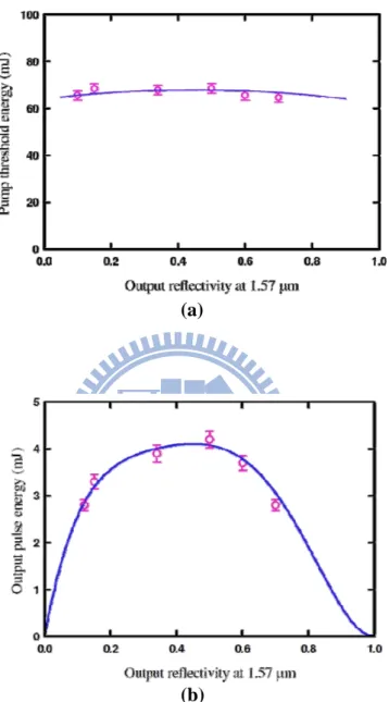
Figure 2.2-4 (a) shows the experimental results for the threshold pump energy versus the OPO output reflectivity. Experimental results confirm that the threshold pump energy is determined by the bleach of the saturable absorber not by the signal output reflectivity. Consequently, a wide range of the signal output reflectivity can be used to optimize the output performance. Figure 2.2-4 (b) depicts the experimental results for the pulse energy of the signal output versus the signal output reflectivity. The optimal output reflectivity for the output pulse energy can be found to be within Rs =40~50%. With the optimum output coupler, the conversion efficiency from the diode input energy to the signal output energy is approximately 7%, which is slightly superior to the efficiency of 4~6% obtained in a coupled cavity [13].
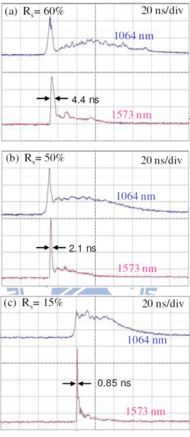
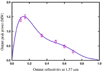
Figure 2.2-5 (a)-(c) show the experimental results for the temporal shapes of the fundamental and the signal pulses obtained with three different output couplers. It can be seen that the pulse durations of the signal output are 4.4 ns, 2.1 ns, and 0.85 ns for Rs=60%, 50%, and 15%, respectively. The pulse width obtained with Rs = 15% is 2.4 times shorter than that obtained with Rs = 50%; however, the pulse energy is only 20% less than the maximum value. In other words, the peak power reached with Rs = 15% can be nearly two times higher than that obtained with Rs = 50%. To be more accurate, the output peak was calculated with the experimental pulse energy and the numerical integration of the measured temporal pulse profile. Figure 2.2-6 depicts the experimental results for the peak power of the signal output versus the OPO output reflectivity. The optimal output reflectivity for the output peak power can be found to be within Rs =10−20%. With the optimum output coupler, the maximum peak power can be up to 1.5 MW.
Chapter 2 Passively Q-switched Eye-safe Laser with Optical Parametric Oscillator
Fig. 2.2-4. (a) Experimental results for the threshold pump energy versus the OPO output reflectivity. (b) Experimental results for the pulse energy of the signal output versus the OPO output reflectivity
(a)
Fig. 2.2-5. Experimental results for the temporal shapes of the fundamental and the signal pulses
Chapter 2 Passively Q-switched Eye-safe Laser with Optical Parametric Oscillator
2.3 The influence of birefringence on pulse behavior in OPO
In order to obtain higher output pulse energy, we enlarged the cross section of end surface of lens duct to 3.3 × 3.3 mm2and the diameter of Nd:YAG rod to 6 mm in the setup of Fig. 2.2-1. The initial transmission of saturable absorber, Cr4+:YAG, is designed to be 51%. The QCW pump diode stack consists of six 10-mm-long diode bars generating 130 W per bar, for a total of 780 W at the central wavelength of 808 nm. The coupling efficiency of the lens duct was measured to be approximately 88%. Several output couplers with different reflectivity were used to investigate the output performance and characteristics. Figure 2.3-1 shows the experimental result about the output pulse temporal behavior at 1573 nm for different reflectivity of output coupler, R=9, 16, 34, and 50%, respectively (Wave pro 7100, 10G samples/sec, 1 GHz bandwidth). The output pulse energy ranges from 11 to 9 mJ corresponded to increasing reflectivity. As shown in Fig. 2.3-1, in addition to the first transient peak, another longer pulse was generated adjacent to first one in the cases of reflectivity higher than 16%. With higher output reflectivity, the ratio of second pulse is higher. This is rarely seen in the configuration of external cavity OPO since the generation of fundamental pulse and signal pulse are separated. I will demonstrate in next section that the satellite pulse is resulted from the depolarized fields in the resonator during the process of pulse formation by rate equations. The depolarization is caused by the Nd:YAG rod which acts as a birefringence element under high pump power. The electric fields between the phase-matching direction and the other orthogonal direction couple mutually after each round trip propagation. The energy transformation between two axes exhibits a perturbation in the Q-switch and OPO process. Consequently, the decline and growth of energy in the phase matching direction gives rise to an adjacent parasitical pulse.Chapter 2 Passively Q-switched Eye-safe Laser with Optical Parametric Oscillator
Fig. 2.3-1. The output temporal pulse at 1573 nm for different reflectivity of output couple
R=50% R=34% R=9% R=16% 10 ns/div 20 ns/div 20 ns/div R=34% 20 ns/div R=50% R=9% R=16% 10 ns/div 20 ns/div 20 ns/div 20 ns/div
2.3.1 Theoretical analysis and discussion in birefringence effect
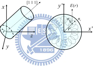
Figure 2.3-2 depicts the typical thermally induced birefringence effect in a Nd:YAG rod with [111] crystal orientation [15]. The principle axes of the induced birefringence are radially and tangentially directed at each point in the rod cross section. In the propagation of electric field along the rod orientation, a linearly polarized field would suffer a phase difference between radial and tangential direction and turn into elliptically polarized. When a linearly polarized field is along y-axis of the rod cross section, it will be gradually depolarized after propagation and resolved into two components along x- and y-axis. This depolarization indicates an energy coupling and transformation between two axes. If the resonator contains a polarizing element to maintain the polarization of fields on y-axis, the field depolarized into
x-axis would be filtered out and becomes a depolarization loss. Without any polarizing
element in the resonator, on the contrary, the energy will flow back after multiple round trips. The proportion of energy transformation, Γ, between two orthogonal axes after a round trip could be estimated from the phase difference δ given by [15]
2 ( )r
π
n r( ) 2l dlcrδ
λ
=∫
Δ ⋅ (2.1-4) 0 2 2 2 0 0 sin (2 )sin ( )2 r rdrd πδ
ϕ
ϕ
Γ =∫ ∫
(2.1-5) where λ denotes the optical wavelength, Δn is the difference of refractive index changes between tangential (Δnψ) and radial (Δnr) direction, lcr is the length of Nd:YAG rod, r and φ are the radius and azimuth angle of any interesting point in the cylindrical coordinate system of the rod cross section as depicted in Fig. 2.3-2, and the upper limit r0 of integral about r is confined to the beam radius of wave in the crystal. The difference of refractive changes is mainly related to the deposited heat in the crystal. For Nd:YAG, it could be expressed as [15]Δn(r)=Δn −Δnr =
(
3.2×10⁻⁴)
⋅Q(l)r2φ , (2.1-6)
where Q is the heat deposited in the crystal per unit volume in the dimension of watts per cubic meter and r is in the dimension of meters. For an end-pumped scheme in our experiment,

![Fig. 1.5-4. The method of thermal management: (a) Heat minimization by thinning the device or bonding a transparent heat spreader [22]](https://thumb-ap.123doks.com/thumbv2/9libinfo/8694483.198651/36.892.205.733.194.816/method-thermal-management-minimization-thinning-bonding-transparent-spreader.webp)