ON-LINE PLANNING FOR AN INTELLIGENT OBSERVER
IN A VIRTUAL FACTORY
Tsai-Yen Li
Computer Science Department
National Chengchi University,
Taipei, Taiwan, R.O.C.
E-mail: li@cs.nccu.edu.tw
Tzong-Hann Yu
Computer Science Department
National Chengchi University,
Taipei, Taiwan, R.O.C.
E-mail: g8801@cherry.cs.nccu.edu.tw
Yang-Chuan Shie
Computer Science Department
National Chengchi University,
Taipei, Taiwan, R.O.C.
E-mail: s8536@cherry.cs.nccu.edu.tw
Abstract
In tele-present or tele-operation applications, an intel-ligent observer is a virtual camera that can perform autonomous motions to assist a user in accomplishing de-sired observing tasks. In this paper we consider the problem of generating and modifying the motions of an intelligent observer tracking a moving target in an online manner. Given the target's trajectory, we first plan the observer's motion to maintain visibility with the target while optimizing certain time-dependent camera-specific criteria. During the execution of the motion, we allow a user to interactively command the observer to deviate from the planned path while guaranteeing visibility with the target in the remaining motion. The online nature of the problem imposes a con-straint on the planning time allowed in each execution cycle. Efficiency of the motion planner becomes the greatest con-cern. In this work we formulate the problem in the relative configuration-time space (CT-space) of the observer and adopt a best-first algorithm to search for a feasible path. In addition, we propose an incremental backward search algo-rithm in the CT-space to handle dynamic modification of the planned path. Simulation experiments show that the planner can generate a feasible tracking path in fractions of a sec-ond and maintain validity of the planned path for each exe-cution cycle in tens of milliseconds. This planning efficiency is achieved partly due to an efficient visibility detection al-gorithm that we have developed for planning tracking mo-tions. This implemented intelligent system is part of an in-teractive3D auto-navigation system for virtual factories. We believe that these experimental results can inspire a new line of potential applications that could benefit from active, in-telligent observations.
Keywords: Motion Planning, Intelligent Observer,
Tele-present, On-line Planning, Intelligent Tracking, Visibil-ity Planning, Virtual RealVisibil-ity, and Virtual Factory.
1.
Introduction
Tracking a moving object by maintaining a continu-ously non-obstructive view presents a great challenge for computers as well as for human. Human professionals usu-ally follow common cinematographic idioms to create cer-tain artistic effects. Before a film is taken, the professionals need to plan their camera motions ahead of time in order to maintain good visibility with the subject. If the spatial rea-soning model behind the planning process can be success-fully created in the computer, we can potentially open up a new dimension of interesting applications. For example, a computer-controlled camera can then present a sequence of non-obstructive image or a video segment to a surgeon dur-ing a medical operation. An active vision system with such a tracking capability can be mounted on a mobile robot to provide intelligent surveillance services.[4] In tele-presence or virtual-world applications, by delegating motion tracking to the computer, we can greatly increase the level of control required from a remote user.
The on-line motion-tracking problem considered in this paper was motivated by a virtual presence application for virtual factories.[13] An intelligent tracking module is part of our work on building an auto-navigation system that can generate customized guided tours in an online manner. In this system, a user expresses his/her viewing preferences and points of interests by directly clicking on a 2D-layout map of the virtual world. The system will then generate an
motion of a virtual camera will be planned to track the hu-man motion. In this context, the object to be tracked, called target, is the tour guide, whose motion is known, while the tracking agent, called observer, is the virtual camera in the virtual world.
Such an auto-navigation system alleviates a user from low-level control of 3D-navigation interface with a 2D mouse. Nevertheless, the planner-generated observing mo-tion may not satisfy the user all the time. It is highly desir-able to allow the user to interactively modify the generated camera motion during run-time execution. However, visi-bility with the target under such user intervention may no longer be guaranteed. One can evoke the planner on-line whenever the user changes the camera configuration in or-der to generate a new tracking motion. However, the effi-ciency of motion planners reported in the literature is not good enough for such an on-line demand (within the cycle time of a execution loop or update time of a graphical inter-face).
In this paper, we present our approaching to making on-line planning for tracking motion feasible. We report improvement on the efficiency of our previously proposed work on planning intelligent tracking motion and extend the planner to handle the case of on-line modification of ob-server’s configuration. Specifically, we have developed an efficient collision check routine to speed up visibility detec-tion and proposed an incremental search algorithm at run-time to distribute planning into each execution cycle. Our experiments show that the efficiency of the planner allow the user to safely interact with the camera in an on-line manner that guarantees visibility with the moving target.
In the next section, we describe previous researches pertaining to this work. In Section 3, we give a formal de-scription of the basic and extended tracking problems we consider. Several user-specified criteria used in searching for a tracking motion are also described in details. In Sec-tion 4, we propose our approach that uses an incremental backward search to ensure satisfaction of visibility con-straint under user intervention. Implementation details of this planner and experimental results are given in Section 4. We conclude the paper by discussing possible extensions of this planning system in the last section.
2. Related Work
Visibility computation has attracted many attentions in computer graphics and robotics. In computer graphics, visi-bility information can be used for geometry culling in in-teractive 3D graphics such as building walkthrough [19] or it can be used to facilitate illumination computation [18]. In computer animation, a camera can be controlled to satisfy constraints such as fixing points in a image space[2] or be
commonly used in Cinematography[6]. The issue of intelli-gent camera control has also been addressed in [2][13] to enable task-level control of a virtual camera in a virtual world. In robotics, the general motion planning problems are described in [9]. On-line motion planning for two robot arms has also been considered in [12] but not for visibility computation. Visibility planning considers the problem of placing sensors at appropriate locations to ensure the visi-bility of certain objects. Installing a minimal number of sensors in a static manner is the so-called art gallery prob-lem [1][16] while allowing the sensors (usually cameras) to move actively is the so-called pursuit-evasion problem [5]. Camera motions are usually controlled via an active vision system, and the motion can also be integrated into control servo loops [7][17].
Similar planning problems about maintaining object visibility were considered in [10] for robotics applications. A general dynamic programming approach was used to generate motions for a mobile robot (as an observer) to keep track of a moving target with a (partially) known trajectory. If the motion of the moving target is predictable, an optimal tracking motion for the observer can be generated in an off-line manner. If the target's motion is only partially pre-dictable, on-line motion strategies are used instead. How-ever, the reported planning time of the off-line planner is too long (about 20 sec. on a modern workstation) to be used in an interactive application even for a simplified view model. In [14], a problem similar to the off-line planning case but with more practical considerations for on-line uses is modeled in the configuration-time space relative to the target. The improved planning time for finding a feasible tracking motion ranges from fractions of a second to a few seconds.
3. The Planning Problem
In this section, we first describe our view of the basic motion-planning problem of maintaining visibility with a moving target, as presented in [14]. Then we extend the formulation to consider the problem of allowing dynamic modification of the observer’s motion in an on-line manner.
3.1. The basic tracking problem
We assume that a moving target r and an observer o (or camera interchangeably) exist in a bounded 2D Euclidean workspace W cluttered with obstacle regions B. Although the target and observer all exist in a 3D environment, it is reasonable in our application to confine their motions in a 2D plane to reduce the computational complexity of the problem. The configurations of r and o are parameterized by qr=(xr, yr, θ r) and qo=(xo, yo, θ o), respectively. A con-figuration of an object is collision-free if and only if regions
occupied by the object do not interfere with B. The configuration space (C-space for short) of r and o, denoted by Cr and Co, respectively, are the spaces of all possible configurations. Let
C
rfreeandC
ofreedenote the collision-free portions of their C-spaces, respectively. We suppose that the target’s trajectory τr is given as a function of time t and that all qr‘s in the trajectory lie inC
rfree. With this given tra-jectory, we try to find a collision-free path for o in the con-figuration-time space of CT(t, xo, yo, θo) = (xr(t), yr(t), θ r(t), xo, yo, θ o), as formulated in [8][12]. However, not all figurations in CT are legal configurations since a legal con-figuration must also satisfy the visibility constraints of the observer. That is, in a legal configuration, the observer must be able to remain collision-free from the obstacles, and see portion of the target model with its view model (e.g. a view cone with near and far clipping planes). In addition, the neighboring configurations along a path must also satisfy the maximal velocity constraint imposed on the observer.Since the observer’s goal is to track a moving target, it makes sense to specify its configuration with respect to the target's coordinate system. Therefore, as proposed in [14], we specify the observer’s configuration qo’ relative to r by the set of parameters (l, α, β) as shown in Figure 1. This reparameterization equivalently transforms Co into another space Co’ relative to the target’s coordinate system. Simi-larly, CT(t, xo, yo, θo) can be transformed into CT’(t, l, α, β). These three parameters (l,α, β) are called view distance, tracking angle, and view angle, respectively.
In order to reduce the size of search space for our plan-ning problem, we further drop the dimension, β, in CT’ by making the following assumption. We assume that the ob-server can rotate as fast as the target so that we can tempo-rarily lock the view angle β to a fixed value, say 0 degree,
and then remove this parameter from our search space CT’. The resulting configuration-time space CT’’(t, l, α) is what we will consider in the remaining of this paper. After the observer path in CT’’ is found, the parameter β will then be accounted for and added into qo’(l,α, β) in a post-processing step. In order to simplify notation, we will drop the superscript o in symbols for observer configura-tions whenever it does not cause confusions.
3.2. Planning with viewing criteria
In [14], we described a Best-First search algorithm to find a collision-free path, τ, in CT”, connecting the given initial configuration qi to any legal goal configuration qg(tf, *, *) in the final time slice tf, as shown in Figure 2. Any points inside the CTB region are illegal due to geometry or visibility constraints. The search starts from qi and continu-ously explores neighbors of the current configuration that is evaluated to be the “best” according to some cost function. The neighboring configurations also must not violate the maximal velocity constraint vmax imposed on the observer. The cost function used in the Best-First search is defined as a linear combination of the weights on several viewing cri-teria as shown in the following equation.
f(t, l, α, dir) = w1f1(t)+ w2f2(l)+ w3f3(α)+ w4f4(l,α, dir) (1) f1(t) = te – t
f2(l) = |l-l0| f3(α) = |α-α0|
f4(l,α, dir) = dist(p(l, α, 0), p(l, α, dir)),
where
wi: weights for individual cost functions, t: current time,
l: current distance between the viewpoint and the target, α: current tracking angle,
dir: an integer indicating the direction where the current
Figure 1. Workspace and observer (camera) parameters
in a configuration space relative to the target
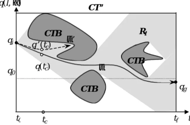
Figure 2. Obstacles (CTB, in dark gray), reachable region
(Rf, in light gray) and a sample feasible path τ in the con-ceptual representation of the configuration-time space (For clarity, the two-dimensional q is shown with one dimension only.) q(l, α)
l
α β observer target qr = (xr, yr, θ r) qo= (xo, yo, θ o ) τr τoW
B
B
B
r o CT” tf t0 t CTB CTB CTB q0 qi qg τ τ’ Rf q’(tc) q(tc) tcconfiguration was created (0 means unchanged), f1: cost function for the distance between the current and
the ending time slices (te is the ending time),
f2: normalized cost function for the view distance (l0 is a
preferred neutral view distance),
f3: normalized cost function for the tracking direction (α0
is a preferred neutral tracking angle),
f4: normalized cost function for the Euclidean
dis-tance moved from the parent configuration,
p: returns the previous position of the observer for the given approaching direction,
dist: returns the distance between two positions. In this cost function, l0 and α0 are the preferred view
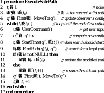
distance and tracking angle specified by the user. In addi-tion, the coefficients wi’s (i = 1 to 4) represent the user’s preference on the weights of the viewing criteria defined by the four individual cost functions. Since these criteria might conflict with each other, deciding the importance of each individual function is a subjective matter. Examples of the tracking path generated by the planner with different weights are shown in Figure 3. The set P=(l0, α0, w1, w2, w3, w4), defined as the viewing preference set, determines the
search result and is specified by a user for a given scenario. A user may specify different P’s for different time windows when tracking a moving target performing different tasks. For example, in tele-present applications, a user may prefer to keep a good view distance from the target when the target transits from one room to another but once the target enters a room, the preference may be changed to avoid unneces-sary moves whenever possible.
3.3.
On-line modification of observer’s motion
The observer’s path τ is sent for execution after it has been generated by the planner. Visibility with the target is guaranteed if the path is followed exactly as planned. How-ever, this first found path by no means is the optimal path according to the given cost function. Therefore, it is highly
planned motion with some provided user interface. For ex-ample, at a given time tc, the observer is supposed to be at some configuration q(tc) if it follows τ. However, the user may command the observer to move to a different configu-ration q’(tc). The problem becomes how to determine if the observer, when moved to q’(tc), can still maintain visibility with the target for the remaining execution time. One can imagine the situation where the modified path gradually deviates from the original one up to a point that the target will inevitably disappear from the observer’s view. For ex-ample, the modified path τ’ in Figure 2 is inside the reachable region Rf from qi under the velocity constraint, but there exist no feasible continuing paths that can bring the observer to the final time tf without bumping into the obstacle regions.
4. The Proposed Approach
In this section we present our approach to incorporat-ing user interactions into the plannincorporat-ing of the observer’s mo-tion. In order to generate tracking motions that are close to what a user expects, we allow the user to interactively spec-ify different viewing preference sets (P’s) at different peri-ods of time in the target’s trajectory. After the observer’s motion has been generated by the planner, we use an on-line planning algorithm in the observer’s execution loop to ex-amine any dynamic modifications of the observer’s motion before the motion is sent for execution. We will also de-scribe an efficient visibility check routine that enables the on-line planning.
4.1. Maintaining visibility at run-time
We would like the user to modify the observer’s path τ in run-time while it is executed. Because the user input is not predictable, we have to ensure that the modified con-figuration remains valid at the sampling rate of the ob-server’s execution loop. At any time step tc, we get a modi-fication command u from the user. This command is sup-posed to bring the observer to a new configuration q’(tn) for the next time step tn. However, the guaranteed visibility for the remaining execution time is lost. Since the time dimen-sion is not reversible, one cannot back up to the original point in CT” either.
One way to ensure this validity is by evoking planning in each execution loop to find a new feasible path connect-ing q’(tn) back to the original path τ or directly to the goals. Currently, the planning times of most known planners range from fractions of a second to a few seconds in average cases. In the worst case, where no paths exist and the whole search space needs to be traversed, the planning time will be too long for on-line uses. Actually, the worst case may happen
Figure 3. An example of viewpoint tracking motion with
emphases on different criteria: preferring keeping (a) a good view distance, l, (b) a good tracking angle, α. (dot: target, circle: observer)
(b) (a)
very often since the purpose of on-line planning in our case is to monitor and eliminate such potential violations.
We approach this problem by incrementally searching the CT” space backward in time along τ in order to find a guaranteed path connecting the modified configuration back to τ. We define τ*(tn) as the subpath of τ for t ≥ tn. Instead of trying to connect q’(tn) forward to some configuration q(tr) in τ*(tn), we connect q(tr) backward to q’(tn). The con-figuration q(tr) is a connecting point in τ*(tn) that brings the observer back to τ. The new subpath connecting q’(tn) and q(tr) is denoted by τr(tn). As shown in Figure 4, Rf denotes the region reachable from qi in CT’’. Rb denotes the region reachable from some point in τ. Equivalently, any points in Rb can be connected to τ under the vmax constraint. The in-tersection of Rf and Rb, denoted by Rc, is the safe region where the modified observer path must lie.
Although conceptually Rc is the region in which one needs to confine the observer’s motion, it may not be a good idea to explicitly compute Rc. If the 3D CT” space is represented in a discrete form of some resolution as in our planner, the number of points to be marked in this region could be very large, especially when the time dimension is long. However, only the portion of Rc that belongs to the vicinity of the modified path τ’ might need to be considered. If the planned path is executed without any modifications, there are even no needs to compute this region. Therefore, we take an on-demand approach that incrementally builds portion of Rc as needed at rum-time. Any points in Rc are marked in CT” after they have been visited.
The algorithm for safely executing the observer’s tracking motion with dynamic modification from a user is outlined in Figure 5. Starting from the initial time t0, we
have to ensure that at any time tc, there exists a safe return-ing sub-path τr(tc) connecting q’(tc) back to some
configura-tion q(tr) in τ*(tc). In each execution step, we search for such a returning sub-path for the attempted new configuration q’(tn) (tn = tc +1) with the given user input u. If the search succeeds, the q’(tn) can be safely executed and the returned subpath τr(tn) is saved for future references. Otherwise, the command u is cancelled and the observer will resume the subpath τr(tc) saved for the current time step.
In the ExecuteSafePath procedure, two subrou-tines need further explanations. The StartTime() subroutine in line 8 determines the time step where the backward search should start. It is the first time index, ts (ts > tc), such that q’(tn) and q(ts) can possibly be connected without violating vmax. The planning process, performed in the FindPath() subroutine in line 9, starts from the configuration q(ts) and search backward in time in a breadth-first manner until the goal (q’(tn) in this case), is reached (success) or all configurations down to the time tn have been exhausted (failure). Due to the vmax constraint, the backward reachable region from q(ts) is a cone-shape region. Since some of the configurations in this cone might have been visited in previous steps, the number of configurations that need to be visited is rather small. In other words, this region is visited incrementally and computation cost is distributed to each execution step. Therefore, such an incremental search strategy is appropriate for planning tracking motion with on-line user modification.
4.2. Fast visibility checks
On-line planning is integrated into the execution loop of the observer’s motion with the help of efficient visibility 1 procedure ExecuteSafePath
2 tc ←1 // ticker
3 τ’ ←τ*(tc) // τ’ is the current valid path 4 q’ ← First(τ’); MoveTo(q’); // update observer’s config 5 while(tc ≤ tf) { // loop until the end of execution 6 u ← UserCommand() // get user input 7 q
”
← q’+ u // compute new config 8 ts ← StartTime(q”, τ*(tc)) // when search should starts 9 τr← FindPath(q(ts), q”) // search for a legal path 10 if (τr is not NULL) then11 τ’←τr + τ*(ts) // update the modified path 12 else
13 τ’←τ’*(tc+1) // resume the old safe path 14 q’ ← First(τ’); MoveTo(q’)
15 tc← tc +1 16 end while 17 end procedure
Figure 5. The on-line planning algorithm during motion
execution for maintaining visibility under user intervention
Figure 4. Forward reachable region Rf, backward projec-tion region Rb, and their cross section Rc in CT”. The planned path τo can be transformed to τo’ only inside Rc.
tf t0 t CTB CTB CTB qi qg CT” τ q’(tc) q(tc) τ’ Rf Rb Rc q(l, α) tc
checks. During the search, visibility with the target deter-mine the legality of an observer’s configuration in the CT” space. Like in most motion planners, collision detection is the most time-consuming routine in the planning computa-tion. A primitive routine for our visibility planning is de-tecting the potential collisions of a line segment with the obstacles in the workspace. For example, with the simplest view model, maintaining visibility could just mean keeping a line segment of variable lengths in the freespace. When the complexity of the environment increases, the collision detection routine will also become more expensive.
To speed up visibility checks, we compute a 3D dis-tance map, denoted by DM, in a preprocessing step for all possible configurations of an observer. The distance infor-mation contained in DM is used to quickly determine if a line segment collides with obstacles in run-time. DM is a 3D uniform grid, in which the coordinate of each cell cor-responds to an observer configuration (xo, yo, θo) in the Cartesian space. The value contained in each cell represents the distance to the first obstacle boundary when we shoot a ray from the corresponding configuration. When doing collision checks for a line segment, we first determine its configuration from one of its end point and look up the cell value for this configuration in DM. If the value is less than the length of the line segment, a collision is implied; otherwise, the line segment is collision-free.
Although DM is computed in a preprocessing step for a given environment, the total computation should not take too long. In [15], a well-known algorithm was proposed to compute C-space obstacles in time linear to the complexity of the obstacles. We adopt this algorithm to efficiently compute DM. In our case, the robot in this C-obstacle computation is a line segment. With this algorithm, one can compute the 3D C-obstacles for such a robot in fractions of a second on a regular PC. A useful observation is that when the length of the line segment changes, the vertices of the C-obstacle polygons are only changed by a constant offset. We compute DM by first initializing it with some large
value. Then we discretize the length of the line segment in its legal range and compute the C-obstacle polygons for each discrete length in a descending order. The interior of the C-obstacles in DM for a given length is filled with the length value. Since the C-obstacle polygons are shrinking gradually as the length decreases, different distance values show up correctly after the iteration on length is finished.
5. Experiments
5.1. Implementation
We have implemented the planning algorithm described in the previous sections in the Java language. At the current stage, the planner contains two parts: a path planning mod-ule that computes sequences of non-holonomic motions for the target, and a motion tracking module that computes tracking motions for the observer. The system runs on regu-lar desktop PC’s or UNIX workstations and provides a graphical user interface for a user to specify the target’s goals and personal tracking preferences such as the weights for various cost functions. During the execution of the mo-tions, a user can use a mouse to input modification to the observer motion. The vector dragged with a mouse is de-composed into the horizontal and vertical components, rep-resenting the desired offsets for the l and α parameters of the observer’s configuration, respectively. In each execution loop, this desired offsets are converted into motion com-mands applied to the current configuration of the observer.
We represent CT” by a three-dimensional uniform grid (a 3D bitmap) as proposed in [12][14]. This bitmap is used to mark the visited configurations in the Best-First search for planning the observer’s tracking motion. The time reso-lution of the CT” space is determined according to the maximal velocity constraint of the observer. During the search, moving a configuration to its neighboring configu-ration in the next time slice will not violate the velocity constraint. The same bitmap, after being reinitialized, is also used to mark visited configurations in the on-line planning
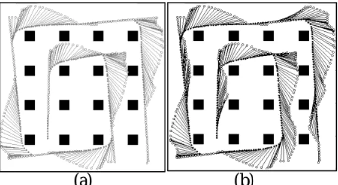
Figure 6. An example of on-line modification of the
ob-server’s tracking motion. (a) the planned path (b) the on-line modified path
Figure 7. Another example of on-line modification of the
observer’s tracking motion. (a) the planned path (b) the on-line modified path
(b)
(a)
+α -α +l -l(b)
(a)
phase.
5.2. Experimental results
The planning time for generating a tracking motion mainly depends on the volume of the regions visited during the Best-First search process. In the worst case where no feasible paths exist, the total number of cells in the free configuration-time space can still be visited in a few sec-onds. In most cases, the running times (measured on a Cel-eron 400 MHz PC) are less than a second with the improved visibility check routine. For the examples shown in Figure 2, the workspace resolution is a uniform grid of 128x128 and each rotational increment is 3 degrees. The minimal, neutral, and maximal view distances (lmin, l0, lmax) are 12, 20, and 60 units, respectively. The tracking angle (α) spans a range of 220 degrees (±110 degrees) with the neutral position being right behind the target. The number of time steps in CT” is 302, and the planning times for both cases are all 0.16 sec-onds (compared to 1.43 secsec-onds, when the improved routine for visibility checks is not used).
Figures 6 and Figure 7 show two examples of on-line modification to the observer’s motions. Part (a) in each fig-ure shows the planned path while part (b) shows the trace of the actual executed path under the influence of user interac-tion. In Figure 6, note that the user modified the planned path during run-time execution by consecutively increasing α, decreasing α, increasing l, and then decreasing l. For the example in Figure 7, out of the 346 execution steps, only 75 modifications are feasible. The remaining illegal ones in-clude the situations where the desired observer configura-tion results in collision or the on-line search fails. The av-erage number of configurations visited in each on-line search is only 23, and the maximal planning time in an execution step is around 60ms (about 230 configurations were visited), which is short enough for on-line uses.
6. Conclusion and Extensions
6.1. Conclusion
Visibility planning has great potential applications in both robotics and computer graphics. Due to the limited time for planning, allowing a user to modify the planned motion for an observer while maintaining visibility with the target in an on-line manner is a new challenging problem. In this paper, we have presented a novel approach to this problem, in which we use an incremental backward search algorithm to distribute planning computation along the ex-ecution of the observer’s motion. An efficient visibility check routine has also been developed to speed up on-line planning. Our experiment shows that the planning time for each execution loop is rather satisfactory for on-line pur-poses.
6.2. Extensions
In this paper we mainly consider the case where the motion of the target is known or predictable while allowing the motion of the observer to be modified on-line. However, in many applications, the target‘s motion is not necessarily known in advance. We can predict the target’s motion and plan the observer’s motion accordingly, but the generated path may become invalid as soon as the target does not move as predicted. Although we can re-plan the path whenever it becomes invalid, the efficiency of our planner is still not good enough to be evoked in every execution cycle. (The planning time in the worst case could be a few seconds when the size of the target’s path is long.) We are developing an on-line planner with a search window (the number of future time steps) that is adjustable according to the available CPU time in each execution cycle. However, in this case, visibility can no longer be guaranteed since the planner only considers a few time steps ahead. Complete-ness and planning time become a tradeoff in this situation. Our preliminary experimental results show that as long as the target does not move too fast and the motion can be reasonably predicted, a small size (e.g. 5 time steps) of planning window will suffice to maintain visibility with the target.
(a)
(b)
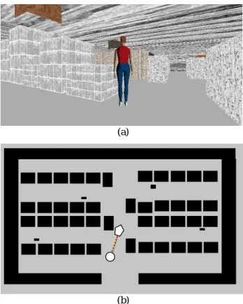
Figure 8. Graphical user interface of the virtual factory. (a)
in a VRML browser, and (b) in a 2D-layout map (pentagon: virtual guide, .circle: virtual camera).
into a virtual presence system that motivated this work. Graphics rendering and user input will be connected to a 3D user interface as shown in Figure 8. In the current user in-terface, modifications made to the planned path are propor-tional to the magnitude of user input along any dimensions. However, it might be more desirable to incorporate some spring model into the interface such that the more the offset is in a dimension, the harder one can adjust the configura-tion along that direcconfigura-tion. In addiconfigura-tion, extending the planner to handle 3D obstacles is also a challenging work that will be considered in the future.
Acknowledgements
This work was partially supported by grants from National Science Council under NSC 89-2218-E-004-002 and NSC 89-2815-C-004-002-E.
References
[1] J. Briggs and B. R. Donald. “Robust Geometric Algo-rithms for Sensor Planning,” J.-P. Laumond and M. Overmars, editors, Proceedings of 2nd Workshop on Algorithmic Foundations of Robotics. A.K. Peters, Wellesley, pp. 197-212, MA, 1996.
[2] S. M. Drucker and D. Zeltzer, “Intelligent Camera Control in a Virtual Environment,” Graphics Inter-face’94, pp. 190-199, 1994.
[3] M. Gleicher and A. Witkin, “Through-the-Lens Cam-era Control,” In E.E. Catmull, editor, Computer Graphics (SIGGRAPH’92 Proceedings), volume 26, pp. 331-340, 1992.
[4] H. H. Gonzalez-Banos, L. Guibas, J.-C. Latombe, S.M. LaValle, D. Lin, R. Motwani, and C. Tomasi, “Motion Planning with Visibility Constraints: Building Autonomous Observers,” Proceedings of the Eighth International Symposium of Robotics Research, Ha-yama, Japan, Oct. 1997.
[5] L. J. Guibas, J.-C. Latombe, S. M. LeValle, D. Lin, and R. Motwani, “Visibility-Based Pursuit-Evasion in a Polygonal Environment,” Proceedings of the 5th Workshop on Algorithms and Data Structures, Springer Verlag, pp. 17-30, 1997.
[6] L-W He, M. F. Cohen and D. H. Salesin, “The Virtual Cinematographer: a Paradigm for Automatic Real-Time Camera Control and Directing,” Proceed-ings of ACM SIGGRAPH’96, pp. 217-224, 1996.
on Visual Servo Control,” IEEE Transaction on Ro-botics and Automation, 12(5):651-670, Oct. 1996. [8] K. Kant and S. W. Zucker, “Toward Efficient
Trajec-tory Planning: The Path-Velocity Decomposition,” In-ternational Journal of Robotics Research, 5(3):72-89, 1986.
[9] J.-C. Latombe, “Robot Motion Planning,” Kluwer Academic Publisher, Boston, MA, 1991.
[10] S. M. LaValle, H. H. Gonzalez-Banos, C. Becker, J.-C. Latombe, “Motion Strategies for Maintaining Visibil-ity of a Moving Target,” Proceedings of the 1997 IEEE International Conference on Robotics and Automation, 1997.
[11] S. Lavallee, J. Troccaz, L. Gaborit, A.L. Benabid P. Cinquin, and D. Hoffman, “Image-Guided Operating Robot: A Clinical Application in Stereotactic Neuro-surgery,” in R.H. Taylor, S. Lavallee, G.C. Gurdea, and R. Mosges, editors, Computer Integrated Surgery, pp. 343-351, MIT Press, Cambridge, MA, 1996. [12] T.-Y. Li and J.-C. Latombe, “Online Manipulation
Planning for Two Robot Arms in a Dynamic Envi-ronment,” International Journal of Robotics Research, 16(2):144-167, Apr. 1997.
[13] T.Y. Li, J.M. Lien, S.Y. Chiu, and T.H. Yu, “Auto-matically Generating Virtual Guided Tours,” in Pro-ceedings of the Computer Animation '99 Conference, Geneva, Switzerland, pp99-106, May 1999.
[14] T.-Y. Li and T.-H. Yu, “Planning Object Tracking Mo-tions,” in Proceedings of the 1999 IEEE International Conference on Robotics and Automation, May 1999. [15] T. Lozano-Perez, “Spatial Planning: A Configuration
Space Approach,” IEEE Transaction on Computers, 32(3):108-120, 1983.
[16] J. O'Rourke, “Art Gallery Theorems and Algorithms,” Oxford University Press, NY, 1987.
[17] N. P. Papanikolopoulos, P. K. Khosla and T. Kanade, “Visual Tracking of a Moving Target by a Camera Mounted on a Robot: A Combination of Control and Vision,” IEEE Transaction on Robotics and Automa-tion, 9(1):14-35, February 1993.
[18] Teller, and P. Hanrahan, “Global Visibility Algorithms for Illumination Computations,” Proceedings of SIG-GRAPH'97, pp. 239-246, 1997.
[19] Teller, and C. Sequin, “Visibility Preprocessing For Interactive Walkthroughs,” ACM Computer Graphics (Proceedings of SIGGRAPH’91), 25(4):61-69, 1991.