國
立
交
通
大
學
資訊科學與工程研究所
碩
士
論
文
在特定應用的超長指令集處理器上產生及使用可重
組態的客製化功能單元
Generating and Exploiting Reconfigurable Custom Functional
Unit in Application Specific VLIW Processors
研 究 生:王惠珊
指導教授:單智君 博士
i
在特定應用的超長指令集處理器上產生及使用可重組態的客製化
功能單元
學生:王惠珊 指導教授:單智君 博士 國立交通大學資訊工程學系﹙研究所﹚碩士班摘要
為了提升針對特殊應用而設計之處理器的效能,可將可重組態的客製化功能單元 ﹙reconfigurable custom functional unit, RCFU﹚ 附加於超長指令字﹙VLIW﹚處理 器架構中。此技術是藉由常出現的運算序列﹙operation segment﹚產生可重組態的客 製化功能單元,並將可以在可重組態的客製化功能單元上執行的運算序列包裹成客製化 指令﹙customized instructions﹚。接下來在程式編譯階段中,指令排程﹙instruction scheduling﹚演算法利用指令的可平行化執行來提升效能表現。此篇研究中,我們不只 提出產生緊密附著於超長指令字處理器的可重組態之客製化功能單元的方法,同時也提 出一個使用此硬體的演算法。我們假設在原本處理器中的功能單元和附加的可重組態的 客製化功能單元可同時執行,且將在過去研究中分成兩個不同步驟的包裹客製化指令及 指令排程整合成一個步驟,以便獲得更多的效能提升及硬體使用率。比較具可重組態的 客製化功能單元處理器及不具可重組態的客製化功能單元處理器的效能表現,整體來 說,在採取我們提出的使用可重組態的客製化功能單元的演算法下產生可重組態的客製 化功能單元的方式相較於過去的產生方式在效能上有大幅的提升;針對如何善用已存在 可重組態的客製化功能單元的架構所提出的演算法也比傳統將找客製化指令及指令排 程分別討論的方式有明顯效能提升。ii
Generating and Exploiting Reconfigurable Custom
Functional Unit in Application Specific VLIW Processors
Student: Hui-Shan Wang Advisor:Dr. Jyh-Jiun Shann
Institute of Computer Science and Engineering National Chiao Tung University
Abstract
To improve the performance of processors, a customized accelerator, reconfigurable custom functional unit (RCFU), may be appended to a very long instruction word (VLIW) processor architecture. The technique is to generate RCFU by those frequent operation segments and collapse operation segments which could be executed on the RCFU as customized instructions. Then, instruction scheduling is done to elaborate instruction-level parallelism for performance improvement at compile time. In this research, we propose not only a tightly-coupled RCFU design on the VLIW processor, but also an algorithm is also proposed to exploit the processor augmented with RCFU. We assume that FUs in the processor pipeline and RCFU could execute simultaneously, and independent operation mapping and instruction scheduling algorithms are integrated into a single phase to get more performance gains and higher hardware usability. We had comparisons between the processors with RCFU and without RCFU. Overall, our proposed RCFU design while using our proposed exploitation algorithm still achieves giant speedup on average over previous generating algorithms. Furthermore, the algorithm for exploiting RCFU also achieves obviously speedup on average over previous methods, separating algorithms.
iii
致謝或序言
感謝我的指導老師 單智君教授這兩年來對我細心地指導,雖然我常常因為理解不 足而無法謹記老師給予的建議,但老師仍不厭其煩的給予指教及親切的關懷、幫助與勉 勵,使我能夠克服求學中所遇到的困難,完成研究及碩士學位。也感謝實驗室的另一位 老師 鍾崇斌教授的諄諄教誨,讓我瞭解到對問題的描述必須精確且扼要。另外也謝謝 我的口試委員 金仲達教授及 馬詠程教授,由於你們的指導和建議,使得此篇論文更加 完整與充實。 感謝吳奕緯學長在研究上給予我許多的建議,使我學習到做研究的態度及方法,以 及可以完成此研究。同時也謝謝不吝給予幫助和意見的實驗室其他學長姐、同學與學弟 妹,你們讓我的研究生活更為充實。 最後要謝謝我的家人與親友,你們的支持與陪伴,一直是我精神上最堅強的支柱。 王惠珊 2009. 9iv
Table of Contents
摘要 ... i Abstract ... ii 致謝或序言 ... iii Table of Contents ... iv List of Figures ... viList of Tables ... viii
Chapter 1 Introduction ... 1
Chapter 2 Background and Related Works ... 5
2.1 Backgrounds – RCFU... 5
2.1.1 Structure of RCFU ... 5
2.1.2 Generation of RCFU ... 6
2.1.3 Exploitation of RCFU ... 7
2.2 Related Works ... 8
2.2.1 Related Work 1: RCFU Generation ... 9
2.2.2 Related Work 2: RCFU Exploitation ... 13
2.3 Opportunity and Evaluation ... 15
Chapter 3 Generation and Exploitation of Reconfigurable Custom Functional Unit (RCFU) Design for VLIW Processors ... 17
3.1 Generation of RCFU... 17
3.1.1 Idea of Our Design ... 17
3.1.2 Algorithm Design ... 18
3.1.3 Example ... 20
3.2 Exploitation of RCFU... 23
3.2.1 Idea of Our Design ... 23
3.2.2 Algorithm Design ... 24
RCFU Mapping and Scheduling ... 25
v
3.2.3 Example ... 28
Chapter 4 Experiment ... 31
4.1 Experimental Setup ... 31
4.2 Experimental Results ... 32
4.2.1 Our Generated RCFU Structures ... 33
4.2.2 Speedups of Our Proposed Exploitation Algorithm ... 37
4.2.3 Performance Comparisons of Our Proposed Design and Related Works ... 39
Chapter 5 Conclusion and Future Works ... 44
vi
List of Figures
Figure 1-1: The relationships among ASIC, GPP and ASP. ... 1
Figure 1-2: (a) Loosely-coupled and (b) tightly coupled accelerator. ... 2
Figure 1-3: (a) Operation segments are extracted from an application. (b) Operation segments are encoded as extended instructions. (c) Extended instructions are executed on the CFUs. .... 3
Figure 1-4: Use an RCFU to replace CFUs. ... 3
Figure 2-1: A base processor augmented with a RCFU. ... 6
Figure 2-2: A conventional flow chart of RCFU generation. ... 7
Figure 2-3: A conventional flow chart of RCFU exploitation... 8
Figure 2-4: Flow chart of RCFU generation in related work 1 ... 10
Figure 2-5: Example of RCFU generation from related work 1: (a) a basic block from an application, (b)-(e) the utilization matrix is used the record the shape of operation segments, (f) the utilization matrix with normalization form, (g) entries with gray color will be implemented as PEs,(h) the generated RCFU ... 12
Figure 2-6: Design flows of customized instruction generation for RCFU exploitation ... 14
Figure 2-7: (a) the generated RCFU; (b) and (c) are the examples of HTTP and VTTP ... 14
Figure 2-8: Example of related work 1 which did not consider read/write port constraint ... 15
Figure 3-1: Flow chart of proposed RCFU generation. ... 19
Figure 3-2: Determination of functionalities of PEs ... 20
Figure 3-3: Example of proposed RCFU generation for operation segment generation. Figure 3-4: operation segments are recorded in (a) utilization matrix (b) operation matrix for add/sub operations (c) operation matrix for logic operation ... 21
Figure 3-5: In this example, there are (a) utilization matrix, (b) normalized utilization matrix, (c)(d) operation matrices and (e) the structure of RCFU... 23
Figure 3-6: Flow chart of proposed RCFU exploitation. ... 25
Figure 3-7: Flow chart of RCFU mapping and scheduling ... 27
Figure 3-8: Flow chart of FUs mapping and scheduling ... 28
Figure 3-9: Example of exploiting RCFU, the inputs are consist of (a) DFGs of basic blocks from an application and (b) two FUs in a base processor augmented with RCFU. ... 29
Figure 4-1: RCFU shape with various coverage rates under 4 read/ 2 write constraint (N = 2) ... 34
Figure 4-2: RCFU shape with various coverage rates under 6 read/ 3 write constraint (N = 3) ... 35
Figure 4-3: RCFU shape with various coverage rates under 8 read/ 4 write constraint (N = 4) ... 36
vii
Figure 4-4: Speedups of RCFU design with varying user-defined coverage rate under 4 read/ 2 write constraint (N = 2) ... 37 Figure 4-5: Speedups of RCFU design with varying user-defined coverage rate under 6 read/ 3 write constraint (N = 3) ... 38 Figure 4-6: Speedups of RCFU design with varying user-defined coverage rate under 8 read/ 4 write constraint (N = 4) ... 38 Figure 4-7: RCFU shape with various coverage rates from related work 1 ... 39 Figure 4-8: Speedups of RCFU design with varying user-defined coverage rate for different generation and exploitation algorithms under 4 read/ 2 write constraints (N = 2) ... 41 Figure 4-9: Speedups of RCFU design with varying user-defined coverage rate for different generation and exploitation algorithms under 6 read/ 3 write constraints (N = 3) ... 41 Figure 4-10: Speedups of RCFU design with varying user-defined coverage rate for different generation and exploitation algorithms under 8 read/ 4 write constraints (N = 4) ... 42
viii
List of Tables
Table 2-1: Proposed design vs. existing method of RCFU generation. ... 15 Table 2-2: Proposed design vs. existing methods of RCFU exploitation. ... 16 Table 3-1: Mapping and scheduling results of the example for proposed design ... 30 Table 4-1: Synthesis results for RCFU designs with varying user-defined coverage rate under 4 read/ 2 write constraint (N = 2) ... 34 Table 4-2: Synthesis results for RCFU designs with varying user-defined coverage rate under 6 read/ 3 write constraint (N = 3) ... 35 Table 4-3: Synthesis results for RCFU designs with varying user-defined coverage rate under 8 read/ 4 write constraint (N = 4) ... 36 Table 4-4: Synthesis results for RCFU designs with varying user-defined coverage rate from related work 1 ... 40 Table 4-5: Performance improvements while comparing the execution cycles of the base processor with a RCFU to the base processor without a RCFU ... 43
1
Chapter 1 Introduction
The researchers have aspired to design high-performance but low-cost computing systems. Application specific integrated circuits (ASICs), fully customized designs, are one of the techniques often used to realize the demands. ASICs provide an effective way to improve performance and decrease energy consumption. Nevertheless, ASICs are not flexible for different applications, indicating that only a few applications could get benefits from the hardwares. In contrast with ASIC, General purpose processor (GPP) is applicable for various applications, but it could not satisfy performance request of the applications with specific requirements.
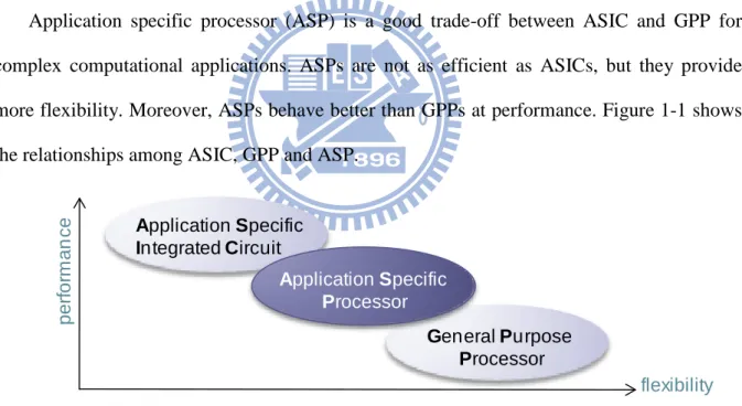
Application specific processor (ASP) is a good trade-off between ASIC and GPP for complex computational applications. ASPs are not as efficient as ASICs, but they provide more flexibility. Moreover, ASPs behave better than GPPs at performance. Figure 1-1 shows the relationships among ASIC, GPP and ASP.
per for m an ce flexibility General Purpose Processor Application Specific Integrated Circuit Application Specific Processor
Figure 1-1: The relationships among ASIC, GPP and ASP.
An ASP contains a base processor which is augmented with accelerators. The implementation of accelerators and base processor can be loosely-coupled or tightly-coupled [1]. A loosely-coupled accelerator accelerating basic blocks or functions of applications
2
appears as a coprocessor which helps balancing the loading between base processor and itself, as shown in Figure 1-2(a). The accelerator communicates with base processor by system buses, hence it has a giant overhead while transferring data. In contrast with loosely-coupled system, tightly-coupled accelerators getting register file directly accelerate extended instructions extracted from applications, as shown in Figure 1-2(b). ASPs utilize the tightly-coupled accelerators integrated into a base processor pipeline. The base processor is augmented with a set of extended instructions to exploit the accelerators. Tightly-coupled accelerators offer several advantages, including decreased execution latency for operations, increased execution bandwidth and reduced accessing register file for temporal data. There is no overhead while transferring data. In this research, we focus on tightly-coupled accelerators.
(a)
(b)
CPU HW accelerator main memory I/O fe tc h issu e…
FU FU wb CPU accelerator regi st erFigure 1-2: (a) Loosely-coupled and (b) tightly coupled accelerator.
For an ASP with tightly coupled accelerator, frequently executed operation segments of applications have been extracted as extended instructions, as shown in Figure 1-3(a) and (b). Extended instructions will be executed on the tightly-coupled accelerators, called custom functional units (CFUs), as shown in Figure 1-3(c). Researchers found that CFUs cause heavy area cost [2]. Obviously, partial functionalities of CFUs are overlapping. Consequently, a reconfigurable accelerator, reconfigurable custom functional unit (RCFU), has replaced CFUs, as shown in Figure 1-4 [3]. Various tightly-coupled RCFU architecture comprise a matrix of
3
processing elements (PEs), which are capable of executing several data-independent or data-dependent operations. Many researchers have proposed these architectures for specific applications. REMARC [4], MorphoSys [5] and ADRES [6] are some of the architectures proposed by academic researches.
(a) (c)
EXE/MEM Pipeline Registers DEC/EXE Pipeline Registers
FU1 … FUm Result bus … Extended instruciton Extended insturction … CFUn CFU1 … (b)
Figure 1-3: (a) Operation segments are extracted from an application. (b) Operation segments are encoded as extended instructions. (c) Extended instructions are executed on the CFUs.
EXE/MEM Pipeline Registers
DEC/EXE Pipeline Registers
FU1
….
FUm RCFURegister file
Figure 1-4: Use an RCFU to replace CFUs.
When RCFU exists in the processor, operation segments to be executed on RCFU would be discovered from applications. In current researches, RCFU and FUs of base processor do not run simultaneously [7]. One of the reasons is that single issue architecture is considered in these researches. The other reason is that, in these designs, there is no need to increase read/write ports. In our experiments, when VLIW architecture is considered, and the number
4
of read/ write ports are not increased, there is 43% of performance improvement on average while RCFU and FUs are running simultaneously. Accordingly, if they are both active, the processor augmented with RCFU would get more performance improvement and higher hardware usability.
In order to increase the speedup of applications, we intend to generate a customized RCFU for computation intensive applications, as shown in Figure 1-4. We concentrate on VLIW architecture that RCFU and FUs could execute simultaneously. To work out the effectiveness of these hardware units, we propose an algorithm to exploit the framework after generating RCFU at compilation time.
The remaining chapters of this thesis are organized as follows: In Chapter 2, we would provide background knowledge and related work about generating and exploiting RCFU. The related works would be introduced and a brief comparison would be made indicating the opportunity we find worth trying for. Our design algorithms of RCFU generation and RCFU exploitation are proposed in Chapter 3, and experimental environment and simulation results are demonstrated in Chapter 4. And finally, Chapter 5, a summary would be made and some future work would be proposed.
5
Chapter 2 Background and Related Works
In the first part of this chapter, we explain the necessary background including conventional RCFU structure, and design issues of RCFU generation and exploitation. In the second part, a brief introduction of generating and exploiting RCFU would be made. Two previous works would be presented and evaluated in more detail.
2.1 Backgrounds – RCFU
Three aspects of background knowledge are introduced in this section. The first part is RCFU structure. The last two parts present the knowledge about generation and exploitation of RCFU.
2.1.1
Structure of RCFU
Extracting operation segments of applications and then executing their corresponding data flow graph (DFG) on the RCFU could get giant speedup. A DFG is a graph which represents data dependencies between operations. A node represents an operation and an edge demonstrates the dependence between two operations.
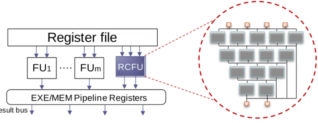
RCFU is implemented as a reconfigurable hardware which is usually a grid-like of coarse grain processing elements (PEs), as shown in Figure 2-1. RCFU allows parallel execution of operations and sequential propagation of data between PEs. There are connections between the different levels of PEs, and data are passed down by the wires.
Each PE may execute an instruction level operation. PE consists of simple computation operations (e.g., adder, subtraction, shift or logic operations) for short execution latencies and
6
slight area costs. In other words, multiply/divide operations are not allowed in PEs because of latency considerations. Load/store operations are also rejected because of cache effects.
Result bus
EXE/MEM Pipeline Registers
DEC/EXE Pipeline Registers
FU1 …. FUm RCFU
Register file
Figure 2-1: A base processor augmented with a RCFU.
2.1.2
Generation of RCFU
Figure 2-2 shows the conventional flow chart of generating RCFU. First, the applications are translated from high level languages (e.g. C/C++) into intermediate representations represented by DFG forms (Step 1). Afterward DFGs are analyzed to decide the shape of RCFU which is characterized by the depth and width. Functionalities of PEs are also pondered at this stage (Step 2). Depth is the maximum length of dependency operations that the RCFU can support. Width is the maximum number of operations which can be executed in parallel. In Step 3, the structure of RCFU is determined by the results of Step 2, according to the hardware constraints, such as the number of read/write port constraints, delay or area cost.
7
Generate Data Flow Graph (DFG) of each basic block Analyze the DFGs Profile the prototype of RCFU
Applications RCFU structure (1) (2) (3) Hardware constraints
Figure 2-2: A conventional flow chart of RCFU generation.
2.1.3
Exploitation of RCFU
The exploitation of the augmented RCFU consists of two steps in backend of compiler: operation mapping and instruction scheduling, as shown in Figure 2-3. In operation mapping stage, all of the operation segments that may be executed on the RCFU are discovered and implemented as customized instructions (CIs). Therefore, there are base instructions and customized instructions after operation mapping. Instruction scheduling is a compilation optimization used to elaborate instruction-level parallelism for performance improvements. Traditionally, operation mapping and instruction scheduling are separated steps. Compilers need to discover CIs to be executed on the RCFU first and then schedule the instructions to optimize the execution.
We are presently considering RCFU and FUs executing simultaneously in multiple issue architecture. Not only have we considered which operation segments can be executed on the RCFU, but we have also deliberated scheduling issue of instructions while doing operation mapping.
8 applications Operation mapping Instruction scheduling base/customized instructions .exe RCFU structure
Figure 2-3: A conventional flow chart of RCFU exploitation.
2.2 Related Works
Critical computation operation segments can be accelerated by collapsing them into customized instructions to be executed on RCFU augmented to the baseline processor. The main objective of RCFU is to execute varied customized instructions as quickly as possible. Many researches for generating specific tightly-coupled accelerators have been proposed [8 - 13]. Each of these techniques employs formulations or heuristics methods to identify operation segments of an application in static time. We have a detailed introduction for one of the algorithm [13] which implements the most common operation segments while keeping cost, delay and area overhead to a minimum.
Discovering optimal set of customized instruction to be executed on the existed accelerator to improve the performance of applications has received a lot of attentions recently [13 - 16]. Clark et al. explore possibly operation segments by starting with small operation segments and expanding them under constraints [13]. Atasu et al. search a full binary tree to decide an operation whether or not to be included in an operation segment [14]. Arnold et al. iteratively detects 2-operator operation segments and replace their appearance in the DFG [15]. Mehdipour et al. adopt temporal partition for the operation segments which
9
could not be execution on the RCFU [16], and we have a detailed introduction for this research.
In this section, we present two related works for designing RCFU and operation mapping algorithm for exploiting RCFU. The two related works are listed as follows:
1. Application-Specific Processing on a General-Purpose Core via Transparent Instruction Set Customization, MICRO, 2004 [13].
2. Custom instruction generation using temporal partitioning techniques for a reconfigurable functional unit, EUC, 2006 [16].
The first related work concentrates on analyzing operation segments of applications to determine the shape and functionalities of PEs in RCFU. The second related work proposes operation segments mapping approach which aims to increase the number customized instructions being executed on RCFU.
2.2.1
Related Work 1: RCFU Generation
As mentioned in section 2.1, RCFU is usually a grid-like group of PEs. The output of PEs in upper levels may communicate with PEs in adjacent lower ones or deliver to the register file. This RCFU generation algorithm proposed by Clark et al. analyzes DFGs of basic blocks from applications to decide the shape, including depth, width, and functionalities of PEs [13]. Its flow chart is clarified in Figure 2-4.
In step 1, operations which are not supported by RCFU, such as load/store, multiply/divide and branch, take a basic block of an application apart. In other words, a basic block is partitioned by unsupported operations into several operation segments. In step 2, in order to generate RCFU with higher usability, a utilization matrix is used to record the shape of each operation segments. A utilization matrix can be seen as a two-dimensional PE array, each entry of the matrix is corresponding to a PE. The parallelism of an operation segment is
10
analogous to the number of columns of the matrix, and the number of operations located on the critical path is analogous to the number of rows. After completing the statistic, the number of operations in each entry of the matrix is divided by the number of total operations to represent the percentage of operations in that PE. Moreover, the percentages of various operations which are presented in these operation segments are also calculated.
In step 3, the depth and width of RCFU are decided by the user-defined coverage rate and the result of utilization matrix. The coverage rate is defined to represent the upper bound of the proportion of the total operations in all the generated operation segments may affect the shape of RCFU. An entry with highest utilization rate is iteratively selected while the sum of selected utilization rate is smaller than coverage rate. The selected entries are implementable by the RCFU. To balance the execution latency and ease the mapping of operations on RCFU, PEs in each level of RCFU is assumed to have identical functionalities in this related work.
Operation segment generation
Operation segment shape & operation type statistic RCFU structure determination
DFG of basic blocks from applications RCFU structure (1) (2) (3) coverage rate
Figure 2-4: Flow chart of RCFU generation in related work 1
This RCFU generation algorithm is illustrated through an example, as shown in Figure 2-5. In this example, assume that there are two types of functionalities supported by RCFU, including arithmetic (e.g., addition and subtraction) and logical (e.g., NOT, AND, OR and XOR) operations. Operations involving more expensive circuits, such as multiplication and
11
division, or having undetermined latencies, such as load/store operations, are excluded. Finally, the value of user-defined coverage rate is assumed to be equal to 95%.
Figure 2-5(a) demonstrates the generated four operation segments (1, 2, 3 and 4) extracted from the basic blocks of applications. Each operation segment is recorded into the utilization matrix, as shown in Figure 2-5(b)-(e). Recall that for the proposed RCFU structure, the result of a PE could only be send to the adjacent lower PEs. When a PE receives data which are not generated from the adjacent upper level of PEs, an adjacent upper PE should be used to pass the information by “move” operations. Figure 2-5(f) shows the result of the normalized utilization matrix.
An entry with maximum value is iteratively chosen to be realized while the sum of chosen entries is no more than the user defined coverage rate. When there exist entries with identical values, the entry on the upper level or left column has higher priority to be chosen. In Figure 2-5(g), the entries with gray color are chosen to be realized.
According to the coverage rate, the shape of RCFU whose depth is equal to 2 is determined. Figure 2-5(h) shows the shape and functionalities of PEs. Because arithmetic operations occupy the largest portion of the operation segments, the arithmetic units would be the main categories of PEs considered for the design of RCFU. To ease the mapping of operations onto RCFU, each level is composed of either arithmetic operation type or logic operation type.
12 xor mov sub and mov add add mov xor mov sub
sub add mov
and or 1 1 1 2 2 2 3 3 3 1 1 4 4 1 4 2 1 1 2 xor and sub add mult sub and add or add xor sub store 3 4 (a) (b) (c) (d) (e) 25% 25% 6.25% 0 25% 12.5% 0 0 6.25% 0 0 0 0 0 0 0 25% 25% 6.25% 0 25% 12.5% 0 0 6.25% 0 0 0 0 0 0 0 (f) (g) (h) : Adder/Subtraction/Move : Logic/Move utilization matrix
normalized utilization matrix
Figure 2-5: Example of RCFU generation from related work 1: (a) a basic block from an application, (b)-(e) the utilization matrix is used the record the shape of operation segments, (f) the utilization matrix with normalization form, (g) entries with gray color will be implemented as PEs,(h) the generated RCFU
13
2.2.2
Related Work 2: RCFU Exploitation
After generating RCFU, a processor is augmented with the generated RCFU which has constraints, including the number of read/write ports and PEs. Identifying optimal set of customized instructions to improve the computational efficiency of applications is the most important issue in exploitation of RCFU. The goal of the RCFU exploitation algorithm proposed by Mehdipour et al. is to maximize the number of operations to be executed on RCFU while FUs of base processor and RCFU do not run simultaneously [16].
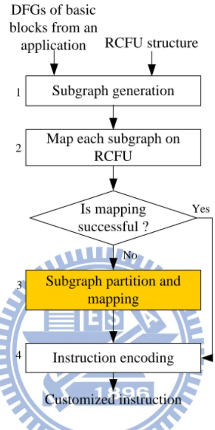
Figure 2-6 represents the flow chart of the exploitation methodology for a generated RCFU proposed by this related work. The inputs are basic blocks from an application in data flow graphs (DFGs) representation and a existed RCFU structure, including the number of inputs, outputs and PEs. In the first step, the DFGs are separated by the operations which are not supported by the RCFU into several subgraphs, by the similar method mentioned in operation segment generation of related work 1. If a subgraph could be successfully mapped onto the RCFU, the subgraph is encoded as a customized instruction, as shown in step 4. Otherwise, the subgraph is split into partial subgraphs to be successfully mapped onto the RCFU.
Two algorithms were developed for subgraph partitioning. The first one is Horizontal Traversing Temporal Partitioning (HTTP). This algorithm traverses DFG nodes horizontally according to the ASAP (As Soon As Possible) level of the nodes and adds them to the current partition. This algorithm usually brings about more parallelism for instruction execution that may result in increasing required intermediate data size. Assume that Figure 2-7(a) is the RCFU generation. The operation segment, as shown in Figure 2-7 (b) could not be mapped onto it. The dotted circle with demonstrates the result for HTTP algorithm. Another partition algorithm, Vertical Traversing Temporal Partitioning (VTTP), vertically traverse the DFG node. VTTP creates partitions with longer critical paths, and thus may reduce the intermediate
14
data size. Using each of these algorithms, all subgraphs were mapped successfully onto RCFU. Figure 2-7(c) shows the subgraph with dotted circle which could be mapped onto the RCFU. However, HTTP may result in better performance improvement, since it benefits from parallelism more in the instruction execution.
Subgraph partition and mapping DFGs of basic blocks from an application Is mapping successful ? Customized instruction Yes No Subgraph generation Map each subgraph on
RCFU RCFU structure Instruction encoding 1 2 3 4
Figure 2-6: Design flows of customized instruction generation for RCFU exploitation
(a) (b) (c) xor or and : Logic/Move : Add/Sub/Move 1 2 0 add 3 xor or and 1 2 0 add 3
15
2.3 Opportunity and Evaluation
In the related work 1, the number of read/write ports provided by a base processor augmented with RCFU is fixed. Nevertheless, read/write ports constraints are not considered while generating RCFU. It means that some operation segments which violate read/write port constraint will not be able to be executed on the RCFU generation. Figure 2-8 shows one of the operation segments and the generated RCFU from related work 1. This operation segment requiring 5 read and 2 write ports could be mapped successfully onto the RCFU, but it could not be executed on the RCFU because of the read/write port constraint of 4 read and 2 write ports.
To balance the execution latency and ease the mapping of operations onto RCFU, functionalities of PEs are identical in each level in related work 1. However, operation types are usually normally distributed in an operation segment according to our experiment. Therefore, restricting identical PEs in each level would cause that customized instructions may contain less operations being accelerated on the RCFU.
(a) (b) sub and add or 4 : Logic/Move : Add/Sub/Move
Figure 2-8: Example of related work 1 which did not consider read/write port constraint
To evaluate a suitable RCFU for applications to get higher performance improvement, we will propose an algorithm of RCFU generation. Table 2-1 gives a preview of our design compared to related work 1.
Table 2-1: Proposed design vs. existing method of RCFU generation.
16
Operation segments conformed # of read/write ports constraints
No Yes
Complexity of generating initial operation segments
Low High
Functionalities of PEs in a level Identical Varied
Related work 2 introduced the method of customized instruction generation for RCFU exploitation. It proposed two algorithms for subgrpah partitioning. Traditionally, the previous research of RCFU exploitation, including related work, identified operations being executed on the RCFU into a customized instruction. After generating all of the customized instructions, instruction scheduling was performed later.
When considering a multiple issue architecture, FUs of the base processor and the RCFU could be executed simultaneously. Aspiring for combining more operations into customized instructions is not absolutely getting higher performance improvement. Since FUs and RCFU could be executed simultaneously, operations which could not be mapped on RCFU can be executed on FUs. Table 2-2 gives a preview of our design compared to the related work 2. Table 2-2: Proposed design vs. existing methods of RCFU exploitation.
Related work 2 Proposed
Occasion for executing
FUs and RCFU Un-simultaneous simultaneous
Operation mapping and instruction scheduling algorithm
17
Chapter 3 Generation and Exploitation of
Reconfigurable Custom Functional Unit (RCFU)
Design for VLIW Processors
In this chapter, there are two subsections, including generation and exploitation, for designing RCFU. First, we present an approach, an improvement from related work 1, of generating RCFU. The main goal aims at creating a more suitable RCFU structure for computation intensive applications. Afterward, a VLIW architecture is augmented with the generated RCFU and we suggest that FUs of the base processor and the tightly-coupled RCFU could be executed simultaneously. An algorithm that integrates operation mapping and instruction scheduling algorithms into an integrated phase, rather than in two separated phases in the previous researches and related work 2 presented.
3.1 Generation of RCFU
The RCFU generation process aims at creating an RCFU structure which has more operations to be executed on it under read/ write port constraint.
3.1.1
Idea of Our Design
As mentioned previously, an RCFU is usually implemented as a grid-like structure of PEs. Analyzing operation segments generated from Data Flow Graph (DFG) of basic blocks from applications is a commonly used technique to settle the shape and functionalities of RCFU. In the related work 1, each operation segment is record to determine the depth and width of the RCFU shape, and the ratio of operation types are calculated to decide the functionalities of
18
PEs. To balance the execution latency and ease the mapping of operations on RCFU, functionalities of PEs are identical in each level in related work 1.
In our proposed design, each operation segment has to conform the read/write port constraints initially. Then each operation segment is record to settle the depth and width of RCFU. Finally, we determine the shape of RCFU by the recording results and user-defined coverage rate. In order to achieve the goal of yielding more operations to be executed on RCFU, the functionalities of PEs are hybrid in each level rather than identical in each level as related work 1 was.
3.1.2
Algorithm Design
Figure 3-1 represents the flow chart of our proposed algorithm for generating RCFU. In Step 1, operation segments are generated. First, Step 1(a), operation segments are extracted from basic blocks of applications according to the algorithm presented in [17]. All of the operation segments are generated to satisfy the read/write port constraints of the base processor. However, there may exist less number of operations in an operation segment. Therefore, in Step 1(b), data-independent operation segments with less number of read/write ports are combined to maximize the number of operations in an operation segment to be executed on the RCFU for making good use of resources. When there exist several data-independent operation segments, which ones would be combined are determined by their priorities. An operation segment which has more operations located on the critical path or contains less number of read/write ports has higher priority. In the combination phase, data-independent operation segments are sorted by their priorities, and an operation segment with the highest priority is iteratively chosen for combination to form a new operation segment under read/write port constraint. In Step 2, a utilization matrix is used to record the depth and width of operation segments, the same as that mentioned in related work 1. Besides
19
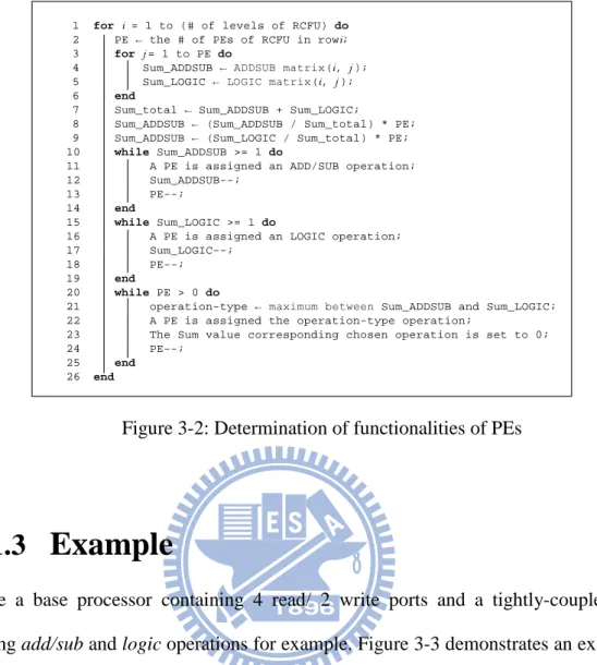
the utilization matrix, we use operation matrices to record the positions of specific operation types in an operation segment. In Step 3, the shape of the RCFU is decided by the utilization matrix and user-defined coverage rate. Moreover, the functionalities of PEs in a row are decided by the ratio in the corresponding row of operation matrices. Figure 3-2 is the pseudo code used to determine the functionalities of PEs. In this algorithm, we assume that addition/subtraction and logic operations are supported by RCFU. The functionalities of PEs in a level would be determined in each loop. The ratio of different operation types is calculated in line 2 to line 9. The PEs are setting functionalities in line 10 to line 19. When there are still existed PEs which are not assigned functionalities, their functionalities are determined in line 20 to line 25.
Operation segment shape & operation type statistic
Shape of RCFU and functionalities of PEs determination DFG of basic blocks from applications RCFU structure 1 Coverage rate Initial generation 2
Operation segment generation
Final combination
3 a b
20
1 for i = 1 to (# of levels of RCFU) do
2 PE ← the # of PEs of RCFU in rowi; 3 for j = 1 to PE do
4 Sum_ADDSUB ← ADDSUB matrix(i, j ); 5 Sum_LOGIC ← LOGIC matrix(i, j ); 6 end
7 Sum_total ← Sum_ADDSUB + Sum_LOGIC;
8 Sum_ADDSUB ← (Sum_ADDSUB / Sum_total) * PE; 9 Sum_ADDSUB ← (Sum_LOGIC / Sum_total) * PE; 10 while Sum_ADDSUB >= 1 do
11 A PE is assigned an ADD/SUB operation; 12 Sum_ADDSUB--;
13 PE--; 14 end
15 while Sum_LOGIC >= 1 do
16 A PE is assigned an LOGIC operation; 17 Sum_LOGIC--;
18 PE--; 19 end
20 while PE > 0 do
21 operation-type ← maximum between Sum_ADDSUB and Sum_LOGIC; 22 A PE is assigned the operation-type operation;
23 The Sum value corresponding chosen operation is set to 0; 24 PE--;
25 end
26 end
Figure 3-2: Determination of functionalities of PEs
3.1.3
Example
Take a base processor containing 4 read/ 2 write ports and a tightly-coupled RCFU supporting add/sub and logic operations for example. Figure 3-3 demonstrates an example for operation segment generation phase. Figure 3-3(a) shows the initially extracted operation segments (1, 2, 3, 4 and 5) conforming the read/write port constraint. The operation segment with highest priority, operation segment 1, is selected, and then the next operation segment, operation segment 2, is chosen. If they are combined, they will still obey the read/write constraints. Figure 3-3(b) represents that operation segment 1 and 2 are combined into a new operation segment 1’. Operation segment 3 would not be combined with operation segment 1’because of constraint, and the like are considered in each data-independent operation segments.
Figure 3-4 represents the detailed procedures for iteratively recording operation segments. Each operation segment is recorded in the utilization matrix, as shown in Figure 3-4(a), and
21
the operation types of operations in an operation segment are recorded accumulatively in the corresponding operation matrices, as shown in Figure 3-4(b) and (c).
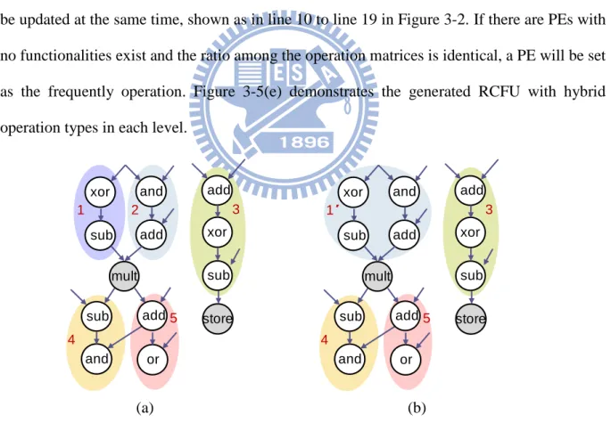
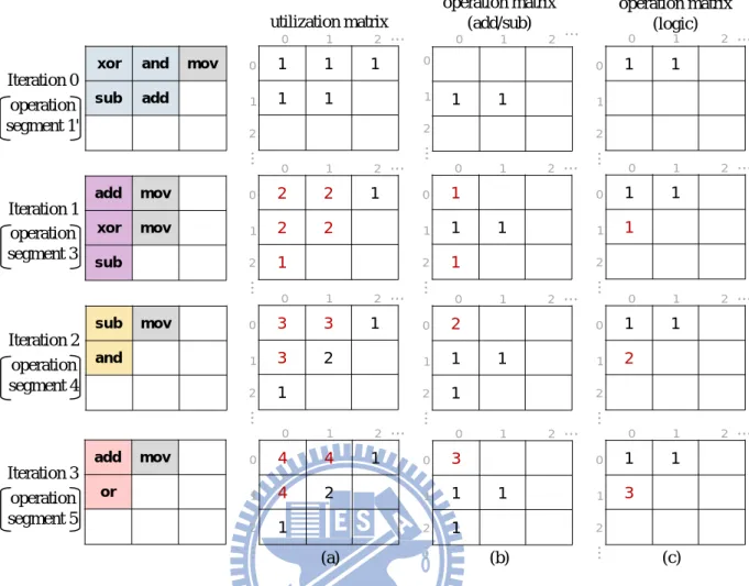
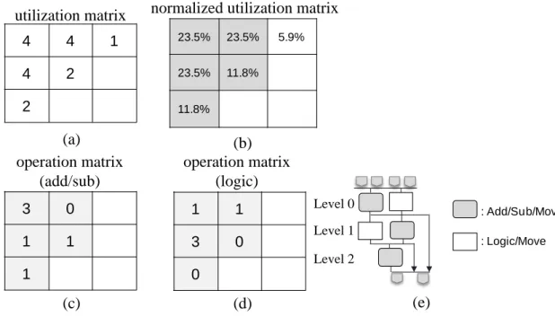
Figure 3-5(a) shows the utilization matrix results from the depth and width of operation segment statistics, and its normalized form in which each entry was divided by the total sum of the entries is represent in Figure 3-5(b). An entry of normalized form represents the percentage of operations to be mapped on that PE. If user-defined coverage rate is equal to 95%, then corresponding PEs of the entries with gray color will be implemented. Figure 3-5(c) and (d) are the results of operation matrices for add/sub and logic operations, respectively. Functionalities of PEs in each level are decided by the ratio of the sum of elements in the same level of operation matrices. When a PE has set some kind of functionality, the ratio will be updated at the same time, shown as in line 10 to line 19 in Figure 3-2. If there are PEs with no functionalities exist and the ratio among the operation matrices is identical, a PE will be set as the frequently operation. Figure 3-5(e) demonstrates the generated RCFU with hybrid operation types in each level.
1 2 xor and sub add mult sub and add or add xor sub store 3 4 5 1′ xor and sub add mult sub and add or add xor sub store 3 4 5 (a) (b)
Figure 3-3: Example of proposed RCFU generation for operation segment generation.
22 (a) (b) (c) 1 1 add mov xor mov sub 0 1 2 … 0 1 2 … 2 2 1 2 2 1 0 1 2 … 0 1 2 … 1 1 1 0 1 2 … 0 1 2 … 1 1 1 1 1 1
xor and mov sub add 0 1 2 … 0 1 2 … 1 1 1 1 1 0 1 2 … 0 1 2 … 0 1 2 … 0 1 2 … sub mov and 0 1 2 … 0 1 2 … 3 3 1 3 2 1 0 1 2 … 0 1 2 … 1 1 2 0 1 2 … 0 1 2 … 2 1 1 1 add mov or 0 1 2 … 0 1 2 … 4 4 1 4 2 1 0 1 2 … 0 1 2 … 1 1 3 0 1 2 … 0 1 2 … 3 1 1 1 Iteration 0 Iteration 1 Iteration 2 Iteration 3 utilization matrix operation matrix (add/sub) operation matrix (logic) operation segment 1' operation segment 3 operation segment 4 operation segment 5
Figure 3-4: operation segments are recorded in (a) utilization matrix (b) operation matrix for add/sub operations (c) operation matrix for logic operation
23 (b) (a)
(c) (d) (e)
utilization matrix normalized utilization matrix
3 0 1 1 1 1 1 3 0 0 4 4 1 4 2 2 23.5% 23.5% 5.9% 23.5% 11.8% 11.8% : Logic/Move : Add/Sub/Move operation matrix (add/sub) operation matrix (logic) Level 0 Level 1 Level 2
Figure 3-5: In this example, there are (a) utilization matrix, (b) normalized utilization matrix, (c)(d) operation matrices and (e) the structure of RCFU
3.2 Exploitation of RCFU
The RCFU exploitation process here could be viewed as a course of mapping and scheduling operations with minimum execution cycles.
3.2.1
Idea of Our Design
Operation mapping phase aims at discovering operation segments that could be executed on RCFU, and collapse these operation segments into customized instructions. Instruction scheduling phase is responsible to decide whether instructions, including base and customized instructions, to be executed on base processor or on RCFU. We focus on the environment that FUs of base processor and RCFU could be executed simultaneously. In order to make good use of the augmented RCFU and reduce the complexity of operation mapping algorithm, we
24
take operation mapping and instruction scheduling into an integrated phase. Mapping maximum number of operations onto the RCFU is not essential necessary in our algorithm, because that some operations which are not chosen to be executed onto the RCFU may be run on the FUs of the base processor simultaneously. In other words, we take the advantage of VLIW architecture that FUs and RCFU could execute simultaneously to improve the execution speedup of applications.
3.2.2
Algorithm Design
Our framework combines the mapping and scheduling phases in a single loop as Figure 3-6 illustrated. DFGs of basic blocks from an application and the generated RCFU structure are the inputs. RCFU has some architectural constraints including the number of inputs, outputs and PEs. The initialization step initializes the variable and data structures, including scheduling_cycle for indicating the current cycle, Unscheduled_List[ ] for storing the unscheduled operations and Ready_List[ ] for storing the ready operations. And then operations are mapped and scheduled on RCFU or FUs until all operations are scheduled. Finally, operations executed on RCFU in the same cycle are encoded into customized instructions.
We will discuss the details of the proposed algorithm in the following paragraphs. First, operations are mapped and scheduled onto RCFU, which provides a list scheduling algorithm to address operations on specific PEs. Second, operations which could not be executed on the RCFU in current cycle are try to be scheduled onto one of the FUs.
25 DFG (G) of an application
Initialization
FUs
mapping and scheduling
Unscheduled_List = {} RCFU structure 1 4 3 Yes. Update current_cycle RCFU mapping and scheduling
2
No.
5 Instruction encoding
End
Figure 3-6: Flow chart of proposed RCFU exploitation.
RCFU Mapping and Scheduling
The RCFU mapping and scheduling process here could be viewed as a course of searching for maximum operations to be executed on the RCFU and FUs of the base processor through Ready_List[ ], which consists of ready operations, as shown in Figure 3-7. We identify ready operations to be mapped onto RCFU on a level-by-level basis. A row of RCFU is defined as a level, and the value of current_level indicates the current level of RCFU, as shown in Step 1.
The algorithm is derived from list scheduling algorithm [18]. The basic idea of list scheduling is to make an ordered list of operations by assigning them priorities, and then repeatedly execute the following two steps until a valid schedule is obtained: (1) Select the operation with the highest priority from the list for scheduling; (2) Select a PE to accommodate this operation. The priorities are determined statically before mapping a level of
26
RCFU, as shown in Step 2. An operation with predecessors being assigned onto RCFU currently has higher priority. When there are operations with the same number of predecessors being assigned, a more critical operation will get higher priority. We calculate the slacks of operations to determine their priority [19]. Slack of each operation represents its criticality. For example, slack equal to 0 means that it is on the critical path. Then an operation with highest priority will be deleted from Ready_List and mapped onto RCFU, as shown in Step 3. RCFU constraints, including the number of inputs, outputs and PEs with specific functionalities, are considered. Detailed speaking, an operation could not violate the constraints and a free PE which could support the operation must exist for successful mapping. If the operation is successfully mapped onto RCFU, the operation will be erased from Unscheduled_Lis, as shown in Step 4 and Step 5. Ready operation with highest priority is iteratively deleted from Ready_List and mapped onto RCFU until the PEs in current level are all occupied or Ready_List is empty, as shown in Step 6. Then next level of RCFU is considered until the value of current_level is larger than the number of rows of RCFU, as shown in Step 9.
27
Update mapping and scheduling priorities of operations in Ready_List Delete operation with
highest priority onto
current_level level of RCFU
Are PEs in current_level level full or Ready_List empty?
current_level++ current_level > the # of levels of RCFU? Yes No Update Ready_List Yes No end 1 2 3 8 Setting current_level = 0 7
Delete operation i from Unscheduled_List 4 Is successful mapping? Yes No 5 6 9
Figure 3-7: Flow chart of RCFU mapping and scheduling
FUs Mapping and Scheduling
After completing RCFU mapping and scheduling, ready operations could be mapped and scheduled onto FUs of the base processor under read/write port constraint, as shown in Figure 3-8. The scheduling method is also derived from list scheduling algorithm. The priority of each operation depends on its slack value. The smaller slack value an operation owns, the higher priority an operation has. An operation with highest priority is deleted from Ready_List and mapped onto FU until there are no available FUs or Ready_List is empty.
28
Update mapping and scheduling priorities in Ready_List Delete operation with highest
priority from Ready_List
Are FUs full or
Ready_List empty?
No Yes
1
2
4 Delete the mapped operation
from Unscheduled_List Is successful mapping? Yes No end Update Ready_List 3 5 6
Figure 3-8: Flow chart of FUs mapping and scheduling
3.2.3
Example
We will clarify the RCFU exploitation algorithm through the example in Figure 3-9. Assume the base processor augmented with RCFU contains 2 FUs in the pipeline and 4 read and 2 write ports, as shown in Figure 3-9 (b). DFGs from basic blocks of an application, as shown in Figure 3-9 (a), is going to be mapped and scheduled on FUs or RCFU. All of the operations in DFGs are first stored in Unscheduled_List = {0, 1, 2, 3, 4, 5, 6, 7} and Ready_List = {0, 1, 4} collects ready nodes which have no predecessors or whose predecessors are all scheduled with priority order.
First, ready operations are mapped and scheduled onto RCFU on a level-by-level basis. We consider each ready operation with highest priority and select a PE in the current level to accommodate it. When current_level = 0, Operation 0 is successfully mapped on PE 0 and operation 1 is mapped on PE 1, and Unscheduled_List becomes {2, 3, 4, 5, 6, 7}. Since there is no PEs available in current level, next level will be considered and current_level is set to 1.
29
Now Ready_List is updated, Ready_List = {2, 4}. The highest priority operation, operation 2, is successfully mapped onto a PE, PE 3, Unscheduled_List = {3, 4, 5, 6, 7}. The other one, operation 4, does not supported by RCFU, so it could be successfully mapped on one of the PEs. Currently, Ready_List is empty, next level will be considered and current_level is set to 2 and Ready_List = {3, 4}. Operation 3 is mapped on PE 4 and PE 3 is used to transform data generated from PE 1, Unscheduled_List = {4, 5, 6, 7}. At this time, the PE in current level is not available, so current_level is set to 3. Mapping and Scheduling for RCFU is complete due to the value of current_level is greater than the number of rows of RCFU.
After completing RCFU mapping, ready operations are mapped on the FUs of base processor. Ready_List = {4} and the operation 4 is mapped on one of the FUs, Unscheduled_List = {5, 6, 7}. Presently, Ready_List is empty and all the scheduled operations are scheduled at the current cycle. Table 3-1 demonstrates the mapping and scheduling results of the example for our proposed design. In the table, “op 0(0)” indicates an operation with index 0 is mapped on RCFU or FU with index 0.
(a) (b) Level 0 Level 1 Level 2 FU1 register file FU0 add or and and add mult add add 1 2 4 5 6 0 3 7 0 1 3 2 4 : Logic/Move : Add/Sub/Move
Figure 3-9: Example of exploiting RCFU, the inputs are consist of (a) DFGs of basic blocks from an application and (b) two FUs in a base processor augmented with RCFU.
30
Table 3-1: Mapping and scheduling results of the example for proposed design mapped on FUs of the
base processor
Mapped on tightly-coupled RCFU
Cycle 0 op 4(0) op 0(0), op 1(1), op 2(2), op 3 (4)
31
Chapter 4 Experiment
In this chapter, experiment methods are described and general recommendations would be suggested base on some environment assumptions and experimental results are submitting.
4.1 Experimental Setup
We implement our proposed design in a C++ environment simulator. Some benchmarks from Mibench [20] were compiled into intermediate representation by the LLVM [21] flow. Mibench consists of six applications including: Automotive and Industrial Control, Network, Security, Consumer Devices, Office Automation, and Telecommunications. The detailed description for each application is listed as follows:
CRC32
The algorithm generates the cyclic redundancy checksum polynomial of 32-bit lengths. This is usually used to validate the integrity of data being transmitted.
dijkstra
The Dijkstra benchmark constructs a large graph in an adjacency matrix representation and then calculates the shortest path between every pair of nodes using repeated applications of Dijkstra’s algorithm. Dijkstra’s algorithm is a well known solution to the shortest path problem and completes in O(n2) time.
blowfish encrypt/decrypt
Blowfish is a symmetric block cipher with a variable length key. It was developed in 1993 by Bruce Schneider. Since its key length can range from 32 to 448 bits, it is ideal for domestic and exportable encryption. The input data sets are a large and small ASCII text file of an article found online.
32
rijndael encrypt/decrypt
Rijndael was selected as the National Institute of Standards and Technologies Advanced Encryption Standard (AES). It is a block cipher with the option of 128-, 192-, and 256-bit keys and blocks. The input data sets are the same as the ones used by blowfish.
Stringsearch
This benchmark searches for given words in phrases using a case insensitive comparison algorithm.
Raw Audio coder/decoder
Raw Audio is an Internet TV & Radio station playing Brisbane music and Australian music. Raw Audio began operations in January 2006 and is now the main place to find Brisbane bands, and watch Brisbane gigs.
To evaluate the proposed hardware and compiler algorithms, there are two phases to be experimented, including RCFU generation and exploitation. In RCFU generation section, base processors with 2N read, N write ports and N FUs, N is equal to 2, 3 and 4, and user-defined coverage rate is set from 10% to 100%. These parameters have strong impact on the shape of RCFU. The number of inputs/outputs in the RCFU also has an effect on the register file since each of the inputs/outputs must be read from or written to it. In RCFU exploitation section, the execution cycles of generated RCFU is set from 1 to k cycles, k is equal to the number of rows of RCFU. The effect of performance is highly dependent on the latency of RCFU.
4.2 Experimental Results
Tailoring RCFU design for each single application can get impressive performance improvements. Nevertheless, there are giant design cost and long time to market. A general RCFU for a domain or a set of applications can get not only performance improvement but a
33
more time-efficient design. In our proposed architecture, the shape and functionalities of RCFU are determined by analyzing recording matrices with different coverage rate in RCFU generation phase. A VLIW base processor augmented with RCFU are experimented in our simulations. We will demonstrate the details of experimental results in the following three subsections. We presented experiment results for N = 2, 3, and 4, where N is the number of FUs in the VLIW architecture. Moreover, the numbers of read ports and write ports of the VLIW architecture are 2N and N, respectively.
We will demonstrate the experimental results in the following three subsections. First, when the RCFU is generated by our proposed design, the representations of RCFU structure and synthesis results are displayed. Second, after adding our generated RCFU, the performance improvements for our proposed exploitation algorithm are shown. Last, we will compare the performance of our proposed methods with that of the related works.
4.2.1 Our Generated RCFU Structures
Figure 4-1 demonstrates the structure of RCFU with N = 2 and varying coverage rate which are automatically generated from domain specific applications, Mibench. Each of these designs was synthesized with Synopsys design tools using a 130nm umc library. Table 4-1 presents the synthesis results for the RCFUs shown in Figure 4-1, including the number of levels of the RCFU, the delay through the RCFU, and the area of the RCFU. The more levels an RCFU has, the longer latency the RCFU executes. For the purpose of providing insight into the cost of adding a RCFU to an actual base processor, note that the area of an ALU with arithmetic and logic operation. The area cost of the RCFU is represented as the number of area cost of ALUs. Figure 4-2 and 4-3 are another different cases, including N= 3, 4, and Table 4-1 and 4-2 are the corresponding synthesis results.
34
In the results of Figure 4-1 to 4-3, the larger coverage rate is, the more PEs a RCFU contains. Obviously, there are longer delays and huger area costs while considering larger coverage rate. Which RCFU structure is more suitable depends on the restraints of the base processor.
Coverage rate = 10% Coverage rate = 20% Coverage rate = 30% Coverage rate = 40% Coverage rate = 50%
Coverage rate = 60% Coverage rate = 70% Coverage rate = 80% Coverage rate = 90% Coverage rate = 100%
A A L L A A A L A L S L A A L A S S L L A A A A A L A L A A L L A A L A L S L A A L A L S L
A Add/Sub/Move L Logic/Move S Shift/Move
Figure 4-1: RCFU shape with various coverage rates under 4 read/ 2 write constraint (N = 2)
Table 4-1: Synthesis results for RCFU designs with varying user-defined coverage rate under 4 read/ 2 write constraint (N = 2)
10% 20% 30% 40% 50% 60% 70% 80% 90% 100%
# of levels 1 1 2 2 2 2 3 3 3 4
Delay (ns) 1.33 1.33 1.43 1.43 1.43 1.43 2.44 2.44 2.44 4.11
Area (# of
35
Coverage rate = 10% Coverage rate = 20% Coverage rate = 30% Coverage rate = 40% Coverage rate = 50%
Coverage rate = 60% Coverage rate = 70% Coverage rate = 80% Coverage rate = 90%
A A L A S A L L L A L L A A L A A L S A A L A S A L L A A A L A S A L L L A L L S A A L A L A A L
A Add/Sub/Move L Logic/Move S Shift/Move
Figure 4-2: RCFU shape with various coverage rates under 6 read/ 3 write constraint (N = 3)
Table 4-2: Synthesis results for RCFU designs with varying user-defined coverage rate under 6 read/ 3 write constraint (N = 3)
10% 20% 30% 40% 50% 60% 70% 80% 90% 100%
# of levels 1 2 2 2 2 2 3 4 4 8
Delay (ns) 1.33 1.43 1.43 1.43 1.43 1.43 2.77 2.87 2.87 10.38
Area (# of
36
Coverage rate = 10% Coverage rate = 20% Coverage rate = 30% Coverage rate = 40%
Coverage rate = 50% Coverage rate = 60% Coverage rate = 70% Coverage rate = 80%
A A L A A L S A A A L A S A L A L A A L A A A S L S A A L A A A S S L A A L A L L A A A L A A A S L A A L S
A Add/Sub/Move L Logic/Move S Shift/Move
Figure 4-3: RCFU shape with various coverage rates under 8 read/ 4 write constraint (N = 4)
Table 4-3: Synthesis results for RCFU designs with varying user-defined coverage rate under 8 read/ 4 write constraint (N = 4)
10% 20% 30% 40% 50% 60% 70% 80% 90% 100%
# of levels 1 2 2 2 3 3 4 4 8 8
Delay (ns) 1.33 1.43 1.43 1.43 1.43 2.77 3.68 3.78 10.31 10.31
Area (# of
ALUs) 0.70 0.96 1.66 2.71 3.44 4.96 5.68 8.38 16.07 27.14
From the simulation results, we have found that the larger coverage rate is, the huger area cost contains. And the more levels an RCFU has, the longer latency the RCFU executes. According to the constraints of the base processor, a suitable RCFU structure is determined. Take a 500MHz base processor with 6 read ports and 3 write ports for an example, the RCFU with 60% coverage rate may be chosen as the generated RCFU.
37
4.2.2 Speedups of Our Proposed Exploitation
Algorithm
The speedups will be addressed after adding the RCFU into the base processor, as shown in Figure 4-4, 4-5 and 4-6. They show the speedups that were achieved for execution cycles by using a base processor augmented with a 32-bit RCFU while comparing with a base processor without RCFU. In these graphs, the first bar indicates the speedup of the base processor augmented with a single-cycle RCFU. The second bar and the like demonstrate the speedup achieved by the base processor with a two-cycle RCFU and so on.
The results show that the RCFUs with higher coverage rate gain higher speedups. One trend to note in these graphs is that a RCFU with longer execution cycles may decrease the performance improvement. Intuitively, operation segments with longer latencies have less speedups. Furthermore, when the coverage rate is equal to 90% under 4 read/ 2 write situation, and the execution latency of the generated RCFU is longer than 3 cycles, there is no benefit while adding the accelerator.
0.8 0.9 1 1.1 1.2 1.3 1.4 1.5 1.6 1.7 1.8 1.9 10% 20% 30% 40% 50% 60% 70% 80% 90% 100% s peedup coverage rate
1 cycle 2 cycles 3 cycles 4 cycles 5 cycles 6 cycles 7 cycles
Figure 4-4: Speedups of RCFU design with varying user-defined coverage rate under 4 read/ 2 write constraint (N = 2)
38 1 1.1 1.2 1.3 1.4 1.5 1.6 1.7 1.8 1.9 2 2.1 10% 20% 30% 40% 50% 60% 70% 80% 90% 100% s peedup coverage rate
1 cycle 2 cycles 3 cycles 4 cycles 5 cycles 6 cycles 7 cycles
Figure 4-5: Speedups of RCFU design with varying user-defined coverage rate under 6 read/ 3 write constraint (N = 3) 1.0 1.1 1.2 1.3 1.4 1.5 1.6 1.7 1.8 1.9 2.0 10% 20% 30% 40% 50% 60% 70% 80% 90% 100% s peedup coverage rate
1 cycle 2 cycles 3 cycles 4 cycles 5 cycles 6 cycles 7 cycles
Figure 4-6: Speedups of RCFU design with varying user-defined coverage rate under 8 read/ 4 write constraint (N = 4)
By the statistics, we have found that in the N = 2 case, RCFU with longer execution cycles may cause poor performances, e.g., RCFU with 100% coverage rate and 5 execution cycles. To simply the problem, we take the generated RCFU with single-cycle into
39
consideration. Afterwards, we have the comparisons between the processor with RCFU and without RCFU, the performance improvement of the case with N = 2 is 35% on average. And for N = 3, 4 cases, the performance improvement for single cycle RCFU are 36% and 47% on average.
4.2.3 Performance Comparisons of Our Proposed
Design and Related Works
Figure 4-7 demonstrates the structures of RCFU generated from related work 1. A great diversity of shapes is presented owing to the read/write port constraint that it did not consider. Table 4-4 presents the synthesis results for each of the generated RCFUs of related work 1. We could found that smaller coverage rates, e.g., 10% ~ 50%, result in trivial RCFUs, and larger coverage rate, e.g., 80%, makes giant RCFU.
Coverage rate = 10% Coverage rate = 20% Coverage rate = 30% Coverage rate = 40%
Coverage rate = 50% Coverage rate = 60% Coverage rate = 70% Coverage rate = 80%
A A A L A L A A L S A L S A A A A A A L L L L L L S S S A L S A Add/Sub/Move L Logic/Move S Shift/Move
40
Table 4-4: Synthesis results for RCFU designs with varying user-defined coverage rate from related work 1 10% 20% 30% 40% 50% 60% 70% 80% 90% 100% # of levels 1 1 1 2 2 3 3 6 8 8 Delay (ns) 1.33 1.33 1.33 1.43 1.43 2.44 2.44 4.89 6.23 6.23 Area (# of ALUs) 0.70 0.70 0.70 0.96 0.96 1.64 2.34 9.48 170.99 196.08
Assume that the execution cycle of the generated RCFU is equal to 1 cycle. Speedup results for different generation and exploitation algorithms are shown in Figure 4-8, 4-9 and 4-10 for N = 2, 3 and 4, respectively. For each set of different coverage rate supported, there are three bars displayed: the first one for our proposed generation and exploitation algorithms, the second one for generation algorithm from related work 1 and our proposed exploitation algorithm, and the last one for generation and exploitation algorithms from related works. It provides a comparison of speedups for varying combination of algorithms.
While adopting our proposed exploitation algorithm, the RCFUs generated by our proposed algorithm have higher speedups on average than related work 1. The reason is that there are more constraints considered in our method, including the number of read and write ports. On the other hand, while considering identical RCFUs generated form related work 1, our proposed exploitation algorithm gets higher speedups than the exploitation algorithm from related work 2. One of the reasons is that it first mapped all of the operations which could be supported by RCFU onto the RCFU, then doing scheduling phase. Nevertheless, we considered operations to be mapped on the RCFU or FUs simultaneously.
41 1 1.2 1.4 1.6 1.8 2 10% 20% 30% 40% 50% 60% 70% 80% 90% 100% s peedup coverage rate
our generation algorithm + our exploitation algorithm related work 1 + our exploitation algorithm
related work 1 + related work 2
Figure 4-8: Speedups of RCFU design with varying user-defined coverage rate for different generation and exploitation algorithms under 4 read/ 2 write constraints (N = 2)
1 1.2 1.4 1.6 1.8 2 10% 20% 30% 40% 50% 60% 70% 80% 90% 100% s peedup coverage rate
our generation algorithm + our exploitation algorithm related work 1 + our exploitation algorithm
related work 1 + related work 2
Figure 4-9: Speedups of RCFU design with varying user-defined coverage rate for different generation and exploitation algorithms under 6 read/ 3 write constraints (N = 3)
42 0.9 1.1 1.3 1.5 1.7 1.9 2.1 10% 20% 30% 40% 50% 60% 70% 80% 90% 100% s peedup coverage rate
our generation algorithm + our exploitation algorithm related work 1 + our exploitation algorithm
related work 1 + related work 2
Figure 4-10: Speedups of RCFU design with varying user-defined coverage rate for different generation and exploitation algorithms under 8 read/ 4 write constraints (N = 4)
When we take RCFU generation from related works 1 and RCFU exploitation from related work 2, we have found that the shapes of generated RCFUs have giant diversities, as shown in Figure 4-7. And recall that, in the above simulations, we compare the performances between the processor with RCFU and without RCFU, and the execution cycles of the RCFU is assumed to be one cycle. And the detailed simulation results about the average performance improvements of three cases are demonstrated in table 4-5. Case 1 takes RCFU generation and RCFU exploitation from our proposed algorithms. Case 2 consists of RCFU generation from related works 1 and RCFU exploitation from ours. Last, case 3 contains RCFU generation and RCFU exploitation from related work 1 and 2. In each case, RCFUs with different number of levels are assumed various execution cycles.
From the result of the simulations under different cases and various execution cycles, we can discover that our proposed algorithms achieve higher performance improvements. The principle reason is that we considered hardware constraints of base processor in RCFU generation phase. And we deliberated operation mapping and instruction scheduling phases at the same time.
43
Table 4-5: Performance improvements while comparing the execution cycles of the base processor with a RCFU to the base processor without a RCFU
N 2 3 4
# of cycles 1 2 3 1 2 3 1 2 3
Case 1 15.6% 5.1% 2.1% 2.7% 1.9% 1.2% 2.7% 1.8% 1.2%
Case 2 21.9% 8.0% 5.4% 19.4% 15.2% 9.7% 21.2% 19.3% 14.2%
44
Chapter 5 Conclusion and Future Works
In this research, we presented a motivation for considering the environment that FUs of base processor and added accelerator could be executed simultaneously.
A computation accelerator, RCFU, a grid-like of PEs, is added to a VLIW base processor to implement customized instructions. It provides an effective way to improve the performance of specific applications. We present an algorithm to generate RCFU. Nevertheless, an integrated operation mapping and instruction scheduling algorithm is presented to decrease the execution cycles of applications.
RCFU with various PEs in each row has more performance improvement, 32.3% on average, than RCFU with identical PEs in each row when adopting our proposed exploitation algorithm. After generating RCFU, subgraphs from applications are identified and mapped onto this generated RCFU. Experiments show that our integrated algorithm performs on average 20% better than the traditional separated algorithm.
In the previous researches, including ours, DFGs extracted from basic blocks of an application are executed on the accelerator. Several techniques have presented in [13, 17, 22]. As mentioned previously, subgraphs are extracted from DFGs of basic blocks of an application and a control instruction (e.g. branch, jump instruction) may cause the subgraph generation to be stopped. Therefore, small size DFGs own to the short distance control instructions. In fact, small subgraphs have not obvious performance improvement in application execution. Thus, extending subgraphs to contain control instruction to be executed on RCFU may get more speedups. This issue contains control instructions in DFGs and presenting them as Control DFGs (CDFGs). On the other hand, the extended RCFU with conditional execution may support more operations to be executed on RCFU at a time.