Chia-Hao Chang Chao-Jung Chen Yu-Chieh Chuang Guor-Rong Her Department of Chemistry, National Taiwan University, Taipei, Taiwan
Received April 24, 2006 Revised June 21, 2006 Accepted June 22, 2006
Research Article
Analysis of triazines by capillary
electrochromatography/electrospray
ionization-mass spectrometry using a
low-flow sheath liquid interface
CEC-MS has been used for the analysis of eight-triazine herbicides. It showed signifi-cantly better S/N ratio than reversed EOF CE-MS and MEKC-MS, due to the lack of a surfactant in the separation buffer. By optimizing the pH, the organic content of the running buffer, and the separation potential, optimal separation was achieved within 18 min using a running buffer of pH 7.0, containing 70% v/v ACN, and an applied volt-age of 17 kV. Gradient CEC showed superior separation when compared with isocratic elution. The combination of a tapered CEC column and a low-flow interface confers several advantages including better sensitivity, low dead volume, and independent control of the conditions used for CEC separation and ESI analysis.
Keywords: Capillary electrochromatography / Low-flow ESI interface / Mass
spec-trometry / Triazines DOI 10.1002/elps.200600251
1 Introduction
Triazine derivatives are among the most important selective herbicides. Triazine herbicides are usually applied as pre-and postemergent weed control to improve the quality of agricultural products. Because of their wide use and rela-tively high resistance of degradation, both the quality and the quantity of these compounds present important con-cerns about the environment and water control. To achieve high separation efficiency, triazines have been analyzed by CE [1–5] and CEC [6] using UV detection. Because of their high specificity, high sensitivity, and the ability to unam-biguously identify analytes, MS has gained increased attention as a detector for CE and CEC analysis. Triazines have been studied using CZE-MS [7–10]. In one example, in the analysis of an eight-triazine mixture, only four peaks were detected in normal CZE; however, by using dynamic coating of CTAB to reverse the EOF, an improved separation was obtained [7]. Still, the sensitivity was poor compared with the normal CZE. This was due to the competition be-tween the CTAB surfactant and the analytes for ionization. The analysis of triazines by MEKC-MS has also been
reported [10]. In this case, all eight triazines were success-fully separated. Although both the reversed EOF CZE and MEKC utilized surfactants, the latter approach yielded bet-ter sensitivity because of the lower dilution factor for the interface used to couple the separation with ESI-MS. Nevertheless, analyte suppression by SDS was still signifi-cant. To further improve the sensitivity, a low makeup bev-eled tip interface has been proposed [11]. This interface was found to be about four times more sensitive than the low-flow interface in the analysis of triazines.
CEC-MS offers an alternative that retains the separation efficiency of MEKC without using a surfactant. CEC is a hybrid technique that combines the resolving power of CE and the high selectivity of HPLC. Unfortunately, column fabrication for CEC presents a significant technical chal-lenge. In particular, the sintered frits used to retain the stationary phase can be difficult to prepare reproducibly and often lead to bubble formation during CEC analysis [12–14]. Although no frit is needed in open tubular (OT) and monolithic CEC, OT-CEC has limited sample capaci-ty, and a trial and error optimization is often needed to select the composition of the polymerization in monolithic CEC. To take advantage of the large variety of commercial stationary phases for HPLC, packed CEC without the use of frit has been proposed [6, 14–20]. For example, Lord et al. [19] have reported the use of a tapered tip instead of frit at the outlet of a packed CEC column.
Correspondence: Professor Guor-Rong Her, Department of
Chem-istry, National Taiwan University, No.1, Sec. 4, Roosevelt Road, Tai-pei, 106, Taiwan, Republic of China
E-mail: [email protected] Fax: 1886-2-23638058
CEC-MS interface lacks the capability of altering the pH and the composition of the eluent that can be advanta-geous to improve the ESI-MS sensitivity. In order to alleviate the high dilution effect of sheath liquid and also make the final spray solution controllable, a low-flow sheath liquid interface has been proposed in a CE-MS study [10]. The sensitivity of the low-flow (several hun-dred nanoliters per minute) interface was found to be better than a conventional sheath liquid (several micro-liters per minute) interface because of less sample dilu-tion.
In this article, we describe the analysis of an eight-tria-zine mixture by CEC-MS. The conditions required to achieve optimal separation including organic solvent content, pH, and separation voltage are discussed. Be-cause of its sensitivity and simplicity of fabrication and operation, a low-flow interface was adopted in this study. The advantages of CEC-MS in comparison with CZE-MS and MEKC-MS in the analysis of triazines are addressed.
2 Materials and methods
2.1 ChemicalsSimazine, atrazine, propazine, ametryn, prometryn, ter-butryne, prometon, and simetryn were obtained from Supelco (Bellefonte PA, USA). Ammonium acetate, HPLC-grade methanol, ACN, and acetic acid were pur-chased from J. T. Baker (Phillipsburg, NJ, USA) and used without further purification. Deionized water (Milli-Q Water System, Millipore, Bedford, MA, USA) was used for preparation of samples and buffer solutions. The C18 sta-tionary phase (5 mm, 100 Å pore size) was purchased from Macherey-Nagel (Düren, Germany). Silicon dioxide, ammonium hydroxide, and sodium hydroxide were obtained from Sigma Chemical (St. Louis, MO, USA).
the end of the tip using a ceramic cutter aided by visual inspection with a microscope.
The tapered (,15 mm id and 25 mm od) capillary column (,27 cm) was then mounted on a homemade pressure vessel that served as a packing reservoir. A slurry of 5 mg of 5 mm ODS in 1 mL of methanol was sonicated for 20 min to prevent aggregation of particles and subse-quently transferred into the reservoir. The pressure vessel was connected to a nitrogen cylinder. Once high-pressure nitrogen (1500 psi) was provided, the ODS particles were pumped into the capillary and retained in the column. After packing, an inlet frit was made using sodium silicate solution by applying heat with a homemade burner for 8 s. An LC pump was used to remove the remaining sodium silicate solution with DI water.
2.3 Fabrication of a low-flow interface
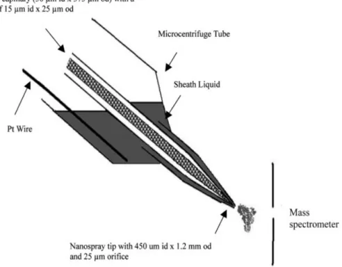
The low-flow interface was fabricated using the method described by Chen et al. [10]. As can be seen in Fig. 1, a 2.5 cm6450 mm id61.2 mm od fused-silica capillary with a tapered tip dimension of 25 mm od615 mm id was fab-ricated. The tip was inserted into a liquid reservoir (a micro centrifuge tube with a drilled hole) and used as the sprayer for ESI. In CEC-MS operation, the makeup liquid was injected into the reservoir using a 500 mL syringe. To minimize the dead volume, the separation capillary was inserted into the very end of the sprayer. Electrical contact was achieved by inserting a platinum (Pt) wire (,400 mm diameter) into the liquid reservoir. On average, the makeup solution was resupplied every ten runs.
2.4 CEC instrument
The CEC instrument was configured in-house. Briefly, the setup consisted of a CZE1000R high-voltage power sup-ply (Spellman, Plainview, NY, USA) connected to a plati-num electrode in a vial containing a running buffer and
Figure 1. Schematic representation of the low-flow sheath liquid CEC/ESI-MS interface.
operated at constant-voltage mode. One end of the separation capillary was inserted into the CEC buffer and the tapered end was inserted into a low-flow interface.
2.5 Mass spectrometer
All MS experiments were conducted on an LCQ ion-trap mass spectrometer (Finnigan MAT, San Jose, CA, USA) and CEC-MS electrochromatograms were acquired in SIM mode. A commercial x-y-z translation stage for the LCQ nanospray source (Protana, Odense, Denmark) was used for mounting the low-flow sheath liquid CEC-MS interface. The position of the interface could be adjusted via the micrometer screws of the translation stage. A nebulizing gas was not necessary, and the heated capil-lary was kept at a temperature of 2507C.
2.6 CEC-MS analysis of triazines 2.6.1 Isocratic CEC
Twenty millimolar ammonium acetate solutions were pre-pared with different ACN content (50, 70, and 90%). The pH of the solution was adjusted to 4.0 with acetic acid and to 7.0, 9.0 with ammonium hydroxide. The makeup liquid (sheath liquid) consisted of methanol, water, and
acetic acid (70:30:1 v/v/v). Before analysis, the capillary was electrokinetically equilibrated at 5 kV for 20 min and at 17 kV for another 10 min. After obtaining a stable baseline, the triazine mixture (20 ppm) was injected elec-trokinetically for 5 s at a voltage of 10 kV. The separation voltage was 17 kV, and the ESI voltage was set at 2 kV.
2.6.2 Gradient CEC
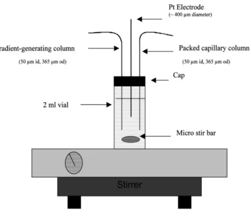
A simple gradient CEC device reported by Medina et al. [31] was modified and used in this work. Briefly, three holes were drilled in the cap of a 2 mL vial (Fig. 2) to allow the insertion of a platinum electrode (,400 mm diameter), a gradient-generating column (365 mm od, 50 mm id), and a separation column into a vial containing the running buffer (20 mM ammonium acetate, ACN/H2O, 50:50) and a microstir bar. The vial was placed on the top of a stirrer (Corning Incorporated Life Science, Acton, MA, USA). Pure ACN was pumped through a gradient-generating column using a syringe pump. In each run, the syringe pump delivers pure ACN at a flow rate of 22 mL/min to change the organic content of the running buffer from 50:50 (ACN/H2O) to 73:27 (ACN/H2O) over 20 min. The sample injection mode, column conditions, and applied voltages were the same as in isocratic CEC.
Figure 2. Schematic repre-sentation of the gradient CEC device.
3 Results and discussion
3.1 Low-flow ESI interfaceFor a tapered CEC column, a sheathless interface is a convenient choice because the tapered tip acts both as a restrictor during column packing and as a sprayer dur-ing CEC-MS analyses. However, similar to the sheath-less CE-MS interface, the sheathsheath-less CEC-MS interface has the problem of finding a solution that is compatible as an eluent and as a spray solution. For example, in a positive ESI operation, an acid (1% acetic acid or 0.1% formic acid) in makeup (sheath liquid) is often added to the spray solution to assist in the formation of preformed ions to enhance ESI signals. However, an acidic solution may not be optimum for analyte separation. In addition, it is much more difficult to repair a CEC-MS sprayer than the sheathless CE-MS interface if the conductive coating peels off from the tip [32]. In practice, to prevent clogging of the tip during the conductive coating process, a high flow of N2or air flowing through the sprayer is needed. As it is not practical to allow N2 flow or air through a column filled with packing material, the CEC column was coated with conductive material prior to packing the column. Consequently, if the conductive coating peels off from the tip, it is difficult to recoat the tip of a packed CEC column.
A low-flow ESI interface (Fig. 1) was used instead of a conventional sheath liquid interface in this study. The low-flow interface consisted of a makeup liquid reservoir and a 25 mm tapered ESI sprayer. A low-flow interface is expected to have better ESI sensitivity than a conven-tional sheath liquid interface because it uses a tip with a smaller orifice (365 mm vs. 25 mm). It is known that the optimal flow rate in ESI depends on the orifice of the emitter [33–35]. For a ,25 mm tip, the optimal sensitivity can be achieved if the flow rate is above 250 nL/min. Our earlier study [10] showed that the flow rate of a ,25 mm low-flow interface was about ,400 nL/min, which is above the optimal flow rate (250 nL/min) but much smaller than the flow of a conventional sheath liquid interface (,4 mL/min). Thus, the problem of sample dilution is sig-nificantly improved. Moreover, when a tapered CEC col-umn is used, instead of a colcol-umn having a sintered frit, the column can be inserted into the very end of the low-flow interface. Thus, the dead volume can be greatly reduced.
3.2 Analysis of triazines by isocratic CEC-MS 3.2.1 Effect of mobile phase composition
In CEC/ESI-MS, it is known that concentration of the buffer affects EOF, buffer capacity, sample adsorption, and peak resolution (stacking effect in higher ionic
strength) [36, 37]. However, in CEC-MS, the major con-cern related to the concentration of running buffer is the ion suppression effect in ESI. An infusion experiment showed that low buffer concentration resulted in better signals (Fig. 3). Therefore, to alleviate ion suppression in ESI but still maintain a reasonable buffer capacity, 20 mM ammonium acetate was chosen in this approach. As shown in Fig. 3, at 20 mM ammonium acetate, the sensi-tivity is more than 70% of the maximum sensisensi-tivity. The percentage of organic solvent in the running solution (mobile phase) not only affects EOF but also influences the partition between stationary phase and mobile phase. ACN was selected as the organic modifier owing to its superior EOF promoting ability [38]. Using a BGE of 20 mM ammonium acetate at pH 7.0, the effect of ACN content on the separation of an eight-triazine mixture was investigated. When 50% ACN was used, low abundance and broad peaks were observed for compounds 1–5 (Fig. 4a), likely because of excessive retention time (40 min). Furthermore, analytes 6–8 were still retained in the stationary phase after 70 min. To increase elution strength, higher percentages of ACN were studied. At 70% ACN, seven peaks were observed although compounds 4 and 5 were coeluted (Fig. 4b). At an even higher elution strength (90% ACN), compounds 3, 5 and 7, 8 were coeluted (Fig. 4c).
Figure 3. Signals of atrazine (1 ppm) at different ammo-nium acetate concentrations in ACN/H2O, 70:30. Signals were acquired in SIM mode (m/z 215–217). Sheath liquid, MeOH/H2O/acetic acid (70:30:1 v/v/v).
3.2.2 Effect of mobile phase pH
As with CEC, the dissociation equilibria of silanol groups on fused-silica column and in the packing material are pH dependent. As a result, the surface charge density, and hence the zeta potential (directly affects EOF) was influ-enced by the pH of the running buffer. Furthermore, be-cause the triazines are nitrogen-containing compounds,
Figure 4. Total ion electro-chromatograms in SIM mode showing effects of percent ACN v/v on the separation of an eight-tria-zine mixture: (1) simaeight-tria-zine, (2) atra-zine, (3) simetryn, (4) prometon, (5) propazine, (6) ametryn, (7) prome-tryn, and (8) terbutryn. Conditions: column, 23-cm packed bed length, 50 mm (id) capillary tapered exter-nally (,15 mm id, 25 mm od) packed with 5 mm C18 stationary phase; mobile phase, (a) 50, (b) 70, and (c) 90% v/v ACN, 20 mM ammonium acetate, pH 7.0, sheath liquid, MeOH/H2O/acetic acid (70:30:1 v/v/v). Electrokinetic injection: 10 kV, 5 s. The voltage applied to the buffer vial was 17 kV and the ESI voltage was set at 2 kV.
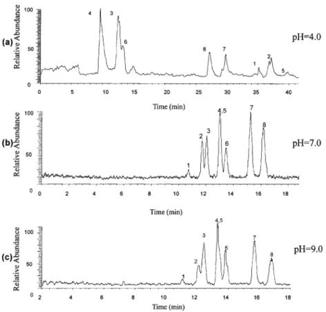
peak broadening of the later peaks could be the result of diffusion owing to the long retention times observed. As can be seen in Figs. 5b and c, the elution order in pH 7.0 and 9.0 was quite different compared with pH 4. It is probable that all the analytes were uncharged at pH 7.0 and 9.0 so that the major separation mechanism was partitioning between the mobile and the stationary phase. In contrast, at pH 4.0 both electrophoretic mobil-ity and partition affect the separation. A significant fact about analysis at neutral or elevated pH is that a higher EOF is induced in the column leading to shorter overall retention times. However, a slightly longer separation
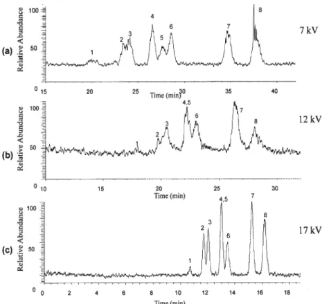
separation voltage of 7 kV, the separation time was about 40 min. It is known that EOF is proportional to the applied field strength and that varying the separation voltage is a practical means to control the EOF in CEC analysis. When the separation voltage was increased to 17 kV, the analy-sis time was reduced to less than 18 min (Fig. 6). At 17 kV, seven peaks were observed as compounds 4 and 5 co-eluted. Although these two compounds could be sepa-rated at lower voltage (7 kV), the peaks were broadened considerably because of diffusion. Considering resolution and separation time, a voltage of 17 kV was chosen as the optimal value for separation.
Figure 5. Total ion electro-chromatograms in SIM mode showing the effect of mobile phase pH on the separation of an eight-triazine mixture. Conditions: mobile phase, 70% v/v ACN containing 20 mM ammonium acetate at pH (a) 4.0, (b) 7.0, and (c) 9.0. All other conditions were the same as in Fig. 4.
Figure 6. Total ion electro-chromatograms in SIM mode showing the effect of applied volt-age on the separation of an eight-triazine mixture. Conditions: mobile phase, 70% v/v ACN containing 20 mM ammonium acetate, pH 7.0. The voltage applied to the buffer vial was (a) 7 kV, (b) 12 kV, and (c) 17 kV. All other conditions were the same as in Fig. 4.
3.3 Analysis of triazines by gradient CEC-MS
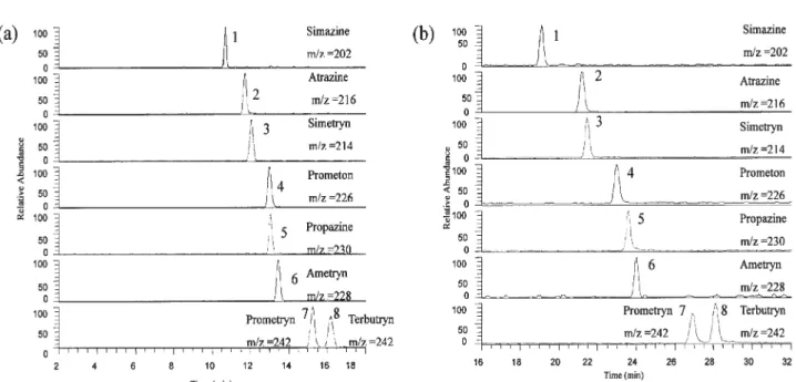
Under the optimal condition of 70% v/v ACN in 20 mM ammonium acetate, pH 7.0, separation voltage of 17 kV, and seven peaks were detected in less than 18 min. However, prometon and propazine were coeluted. To resolve prometon and propazine, gradient elution was employed to improve the selectivity of the CEC separa-tion. For this analysis gradient elution occurred from ACN/ H2O (50:50) to ACN/H2O (73:27) over 20 min. In compar-ison with the data obtained in isocratic elution (Fig. 7a), all the eight triazines were resolved by gradient CEC-MS (Fig. 7b) although the running time (28 min) was signifi-cantly longer than the running time (18 min) used for iso-cratic elution.
3.4 CEC-MS versus CE-MS and MEKC-MS in the analysis of triazines
Triazines have been studied by CZE-MS, reversed EOF CZE-MS, and MEKC-MS [7, 10]. Only four peaks were observed in the analysis of an eight-triazine mixture by CZE-MS. Reversed EOF CZE-MS, dynamically modified with CTAB, provided better resolution than CZE-MS.
However, the sensitivity was adversely affected by sur-factant-induced ion suppression. In MEKC-MS, the eight triazines were baseline resolved. Although SDS was used in the MEKC-MS analysis, the signal suppression by the surfactant, SDS, was attenuated by the use of a low-flow sheath liquid ESI interface which has a small sprayer ori-fice. It has been suggested that because a smaller sprayer produces smaller droplets, a higher surface to volume ratio results in reducing ion suppression [40]. With the use of CEC-MS in the approach presented here, gra-dient elution provided similar resolution as that of MEKC-MS. However, the running time was significantly reduced (28 vs. 42 min). Moreover, the avoidance of a surfactant increased the S/N of the triazines between three- and ten-fold when compared with MEKC-MS [10] using the same low-flow interface. The mass electrochromatograms of a 1 ppm eight-trazine mixture was shown in Fig. 8. On the basis of this data, the detection limit of this approach was estimated to be about 0.5 ppm (based on peak-to-peak). This detection limit was significantly better than that of MEKC-MS using the same interface. The detection limit of this approach was about two times better than that of MEKC-MS using a low makeup beveled tip interface [11]. However, it requires more expertise in fabrication and operation of a low makeup beveled tip interface.
Figure 7. Mass electrochromatograms of the eight triazines using (a) isocratic separation: mobile phase, 70% v/v ACN containing 20 mM ammonium acetate and pH 7.0, (b) gradient separation: mobile phase from (ACN/H2O, 50:50, 20 mM ammonium acetate) to ACN/H2O (73:27) by adding pure ACN at a rate of 22 mL/min. All other conditions were the same as in Fig. 4.
Figure 8. Mass electrochroma-tograms of a 1 ppm eight-triazine mixture. Conditions: mobile phase, 70% v/v ACN containing 20 mM ammonium acetate and pH 7.0. All other conditions were the same as in Fig. 4.
4 Concluding remarks
This work describes the separation of an eight-triazine mixture by CEC-MS using a low-flow interface. A tapered CEC column was used in this study. In comparison with a column prepared using a sintered frit, the tapered column used in this study eliminated the problem of bubble for-mation and reduced the dead volume between the separation column and the low-flow ESI interface. Under optimal conditions, prometon and propazine were unre-solved in isocratic CEC, whereas a gradient CEC pro-vided the separation of all eight triazines. Packed column CEC provides good separation without the use of surfac-tants, such as those found in MEKC and reverse EOF CEC. Therefore, ion suppression by the surfactants dur-ing ESI ionization was alleviated. The use of a low-flow interface provides the advantage of low sample dilution and the capability of using different solution compositions for separation (pH 7.0 in this case) and ionization (1% acetic acid in 70% MeOH). With a tapered packed CEC column and a low-flow interface, CEC-MS has the potential to provide a method with good separation effi-ciency (plug-like flow), good selectivity (the availability of different mobile phases and several stationary phases), good sensitivity (avoidance of surfactant and a low-flow interface), and good specificity (MS detection) for the analysis of organic molecules and biomolecules.
This work was supported by the National Research Council of the Republic of China.
5 References
[1] Schmitt-Kopplin, Ph., Poiger, T., Simon, R., Freitag, D. et al.,
Anal. Chem. 1997, 69, 2559–2566.
[2] Schmitt-Kopplin, Ph., Garrison, A. W., Freitag, D., Kettrup, A.,J. Chromatogr. A 1996, 723, 169–177.
[3] Freitag, D., Schmitt-Kopplin, Ph., Simon, R., Kaune, A., Kettrup, A., Electrophoresis 1999, 20, 1568–1577.
[4] Martínez, R. C., Gonzalo, E. R., Domínguez, A. I. M., Alvarez, J. D., Méndez, J. H., J. Chromatogr. A 1996, 733, 349–360. [5] Penmetsa, K. V., Leidy, R. B., Shea, D., J. Chromatogr. A
1996, 745, 201–208.
[6] De Rossi, A., Sinibaldi, M., Berti, A., Desiderio, C., J. Liq.
Chromatogr. Relat. Technol. 2005, 28, 537–548.
[7] Tsai, C. Y., Chen, Y. R., Her, G. R.,J. Chromatogr. A 1998,
813, 379–386.
[8] Yang, L., Harrata, A. K., Lee, C. S., Anal. Chem. 1997, 69, 1820–1826.
[9] Nelson, W. M., Tang, Q., Harrata, K., Lee, C. S.,J.
Chroma-togr. A 1996, 749, 219–226.
[10] Chen, Y. R., Tseng, M. C., Chang, Y. Z., Her, G. R., Anal.
Chem. 2003, 75, 503–508.
[11] Tseng, M. C., Chen, Y. R., Her, G. R., Anal. Chem. 2004, 76, 6306–6312.
[12] Carney, R. A., Robson, M. M., Bartle, K. D., Myers, P., J.
High Resolut. Chromatogr. 1999, 22, 29–32.
[13] Chen, Y., Gerhardt, G., Cassidy, R., Anal. Chem. 2000, 72, 610–615.
[14] Rathore, A. S., Horvath, C., Anal. Chem. 1998, 70, 3069– 3077.
[15] Baltussen, E., van Dedem, G. W. K., Electrophoresis 2002,
23, 1224–1229.
[16] Chirica, G. S., Remcho, V. T., Electrophoresis 2000, 21, 3093–3101.
[17] Choudhary, G., Horváth, C., Banks, J. F., J. Chromatogr. A 1998, 828, 469–480.
[18] Norton, D., Zheng, J., Danielson, N. D., Shamsi, S. A., Anal.
Chem. 2005, 77, 6874–6886.
[19] Lord, G. A., Gordon, D. B., Myers, R., King, B. W., J.
Chro-matogr. A 1997, 768, 9–16.
[20] Lord, G. A., Gordon, D. B., Tetler, L. W., Carr, C. M., J.
Chromatogr. A 1995, 700, 27–33.
[21] Warriner, R. N., Craze, A. S., Games, D. E., Lane, S. J., Rapid
Commun. Mass Spectrom. 1998, 12, 1143–1149.
[22] Kele, Z., Ferenc, G., E’va Klement, É., Tó th, G. K., Janáky, T., Rapid Commun. Mass Spectrom. 2005, 19, 881–885. [23] Schmeer, K., Behnke, B., Bayer, E., Anal. Chem. 1995, 67,
3656–3658.
[24] Ivanov, A. R., Horvath, C., Karger, B. L., Electrophoresis 2003, 24, 3663–3673.
[25] Viberg, P., Jornten-Karlsson, M., Petersson, P., Spégel, P., Nilsson, S., Anal. Chem. 2002, 74, 4595–4601.
[26] Brocke, A. V., Wistuba, D., Gfrörer, P., Stahl, M. et al.,
Elec-trophoresis 2002, 23, 2963–2972.
[27] Huang, P., Jin, X., Chen, Y., Srinivasan, J. R., Lubman, D. M.,
Anal. Chem. 1999, 71, 1786–1791.
[28] Ding, J., Vouros, P., Anal. Chem. 1997, 69, 379–384. [29] Cherkaoui, S., Cahours, X., Veuthey, J.-L., Electrophoresis
2003, 24, 336–342.
[30] Ding, J. M., Barlow, T., Dipple, A., Vouros, P., J. Am. Soc.
Mass Spectrom. 1998, 9, 823–829.
[31] Medina, J. C., Alonso, M. C., Barcelo, D., Lee, M. L., J.
Microcolumn Sep. 2001, 13, 351–360.
[32] Klampfl, C. W., J. Chromatogr. A 2004, 1044, 131–144. [33] Wilm, M., Mann, M., Int. J. Mass Spectrom. Ion Process
1994, 136, 167–180.
[34] Chang, Y. Z., Chen, Y. R., Her, G. R., Anal. Chem. 2001, 73, 5083–5087.
[35] Zhu, X., Thiam, S., Valle, B. C., Warner, I. M., Anal. Chem. 2002, 74, 5405–5409.
[36] Norton, D., Shamsi, S. A., Electrophoresis 2004, 25, 586– 593.
[37] Dabek-Zlotorzynska, E., Lai, E. P. C., J. Chromatogr. A 1999,
853, 487–496.
[38] Cikalo, M. G., Bartle, K. D., Myers, P., J. Chromatogr. A 1999, 836, 35–51.
[39] Norton, D., Zheng, J., Shamsi, S. A., J. Chromatogr. A 2003,
1008, 205–215.
[40] Juraschek, R., Dulcks, T., Karas, M., J. Am. Soc. Mass