2006 IEEEInternational Conferenceon
Systems, Man, andCybernetics October8-11, 2006, Taipei, Taiwan
Wireless Mesh Networks for Intelligent
Transportation
Systems
Jane-Hwa
Huang, Li-Chun Wang, andChung-Ju
Chang,
Fellow,
IEEEAbstract- Thewirelessmeshnetwork (WMN)is an econom-icalsolutionfordisseminating broadbandwireless information
in the intelligent transportation systems (ITS). This paper
investigates the issue of deploying access points (APs) in an ITS wireless mesh network, whereseveral adjacent APs form a cluster. Each AP in a cluster operates as a wireless relay
to forwardneighboring AP'straffictothecentral access point
connected to the Internet through cables. In general, access
pointsareplacedformaximizingcellcoverage.However, larger coverageofanAP leads to lower throughputand longerdelay
in the access link as well as in the relay link. To find the
optimal tradeoffs among delay, capacity, and coverage, we develop aphysical(PHY)/medium accesscontrol (MAC) cross-layer analytical model to evaluate the throughput and delay
of theconsidered ITSwireless mesh network. Weconsiderthe
carriersensemultiple access(CSMA) protocoland theimpact
ofhop distance on the data rate in the physical layer. Then,
we apply the mixed-integer nonlinear programming (MINLP) optimization approach to determine the optimal number of
APs in a cluster and the best cell radius ofeach AP, aiming
at maximizing the capacity and coverage of a cluster of APs
subjectto the delay andfairness requirements. I. INTRODUCTION
The wireless mesh network (WMN) is a promising
in-formation dissemination technology for the next-generation intelligent transportation systems (ITS) because it can
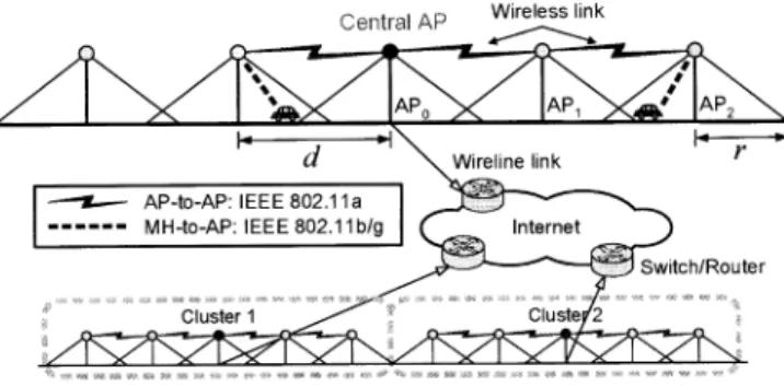
en-hancethroughput andcoverage with lesscablingengineering [1], [2]. Figure 1 illustrates the ITS wireless mesh network scenario considered in this paper. In this ITS wireless
net-work, several adjacentaccesspoints (APs) form acluster. In
each cluster of APs,only the central access point
APO
has awireline connection totheIntemet. OtherAPs communicate with the neighboring APs via wireless link. In addition, eachAPoperates asawireless relay toforward neighboring
AP's traffic toward the central
APo.
By using this multi-hop network architecture, theITS wireless networks can berapidly deployed inlarge scale withlesscablingengineering
work.
Inawireless mesh network, coverage extension,
through-putenhancement anddelay improvement are usually
contra-dictorygoals. On theonehand, maximizingthecellcoverage
of an AP can lower the total infrastructure costs. On the otherhand, alarger cell coverage leads tolower throughput
and longer access delay due to morecollisionsfrom a larger
This workwas supported jointly by MoE ATU Program, the National Science Council and the Program for Promoting Academic Excellence of Universities under thegrand numbers, EX-91-E-FA06-4-4, NSC 95-2752-E-009 -014-PAE, NSC 95-2811 -E-009-030, and NSC 95-2811 -E-009-060.
The authors are with the Department of Communication
En-gineering, National Chiao-Tung University, Taiwan, R.O.C. (e-mail: [email protected]; [email protected]; [email protected])
CeOitralAP Wireless link
Fig. 1. System architecture for an ITS wireless mesh network.
number of contending users. In the meanwhile, the larger
separationdistance between twoAPsalsodecreases the data
rates in the wireless relay link. Therefore, achieving the optimal tradeoffamong throughput, delay, and coverage for each AP is a key challenge for deploying the ITS wireless mesh networks.
In the literature, the issue of access point placement for outdoor WLANs has been studied in [1] and [3]-[8]. In
[3], anintegerlinearprogramming (ILP)optimization model
was proposed for the access point placement, where the
objective function was to maximize the signal level in the servicearea. In [4], anoptimization approach wasproposed
to minimize the areas with poor signal qualityand improve the average signal quality in the service area. The authors in [5] and [6]proposed optimization algorithmsto minimize
averagebit errorrate (BER). In [7], theWLANdeployment problemwas alsoformulatedasan ILPoptimization problem with the objective function of minimizing the maximum of channel utilization to achieve load balancing. However, in
[3]-[7] all the access points are connected to the backbone network through cables. Fewer papers have considered both throughput andcoverageperformanceissues whendeploying access points in theITS wireless networks. The work in [1] investigated the relation of throughput and coverage for an
ITS WMN in a single user case. In our previous work [8], the tradeoff between throughput and coverage in a multi-user ITS WMN was investigated. In [1] and [8], however,
the delayperformance issues were notconsidered.
In this paper, we investigate the AP deployment issue in the ITS wireless mesh network, as shown in Fig. 1. In this ITS wireless meshnetwork, accesspoints areconnected through wireless relays to ease deployment. To find the optimal tradeoffs among throughput, coverage, and delay,
cross-layer analytical model to evaluate the throughput and
delay for this ITS WMN,by incorporating the carrier sense multiple access (CSMA) MAC protocol and the impact of
hopdistanceon the datarate inthephysical layer. On topof
the analytical model, we apply the mixed-integer nonlinear programming (MINLP) optimization approach todetermine the optimal number of APs in a cluster and the best cell
radius foreachAP.Theobjective isto maximize the capacity and coverage of a cluster of APs with delay and delay faimess requirements.
Therest of this paper is organized as follows. Section II
describes the system architecture of the considered ITS
wireless mesh network. In Section III, we formulate an optimizationproblemtomaximize thecapacityandcoverage
of theITS WMNsubjecttothedelay and fairness constraints. Section IV discusses the channel activity in the considered
ITSwireless network.InSectionV,basedonthe channel ac-tivityconcept, wedevelopacross-layeranalytical throughput anddelay model for thisITS WMN.Numericalexamplesare shown in Section VI. Theconcluding remarks are given in SectionVII.
II. SYSTEM ARCHITECTURE ANDASSUMPTIONS
Figure 1 shows the considered ITS wireless mesh network.
Ineachcluster, only the centralaccesspoint
APo
connects to thebackbone network throughcables. Any twoneighboringAPs communicate with each other via wireless link. There-fore, each AP also operates as a wireless relay to forward neighboringAP's traffic to the central accesspoint
APo.
By doingso, thecabling engineering work fordeployingAPs inthe ITS wireless mesh network is reduced.
InthisITSwirelessnetwork,wesuggestutilizingtheIEEE
802.1la WLAN standard for data forwarding between APs, while theIEEE 802.1lb/g for dataaccess between APs and
user terminals. Recall that the IEEE 802.11a WLAN are assigned with eight non-overlapping channels for outdoor applications in the spectrum of 5.25 to 5.35 GHz and 5.725 to 5.825 GHz, while the IEEE 802.1lb/g WLAN
has three non-overlapping channels in the spectrum of 2.4 to 2.4835 GHz. To avoid the co-channel interference and
improve throughput, frequency planning is also applied to
ensure two buffer cells between thetwo co-channelAPs.
III. OPTIMAL ACCESS POINT PLACEMENT
A. Problem Formulation
All the performance issues of throughput, coverage, and delay are essential factors in the design of the ITS wireless mesh network. From the coverageviewpoint, thelarger cell can lower infrastructure cost due to fewer APs. From the
throughput standpoint, however, asmallercell is better since fewer users contend for thespectrum. In addition,the small-sized cell also leads to higher throughput in the wireless
relay link between APs. The main focus of this paper is on the frame delay consisting of contention delay and
queuingdelay in eachrelay node. Fromthe queueing delay perspective, a longer separation distance between two APs may be better due to fewer hops. Fromthecontention delay
Internet ~] AP-to-AP:IEEE802.1a
e MH-to-AP:IEEE3802.llbg \wtrhIRndterd d d d \ 1 J > 2 3 \A P AP AP2 AP H(d1) H(d2) 1(d3) H(d 11(r
R](r1
1(r2)\{ /
|RQT)
\
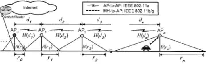
ii Y ~~~~WA W'bFig. 2. A cluster of APs in the ITS wireless mesh network, where only the single side of a cluster is shown since the APs in the other side are deployed symmetrically.
viewpoint, however, asmaller cellcoverflge ispreferreddue
tofewercontendingusers. Inthefollowing,weformulate an
optimization problem to determine the best number of APs in acluster and the optimal cell radius ofeach AP subject to the constraints on delay, throughput, andcoverage.
At first, referring to Fig. 2, we discuss the constraints in
the optimization problem for the considered ITS WMN:
* The access link capacity
R(rQ)
for one usercommuni-cating with AP1 should be greater than the demanded traffic RD of each user. That is, R(r,) > RD, where
ri is the cell radius of APF, as shown in Fig. 2. This
constraintguaranteesthe minimumthroughput foreach user.
* Therelaylinkcapacity
H(di)
betweenAPF andAP11 should be larger enough to accommodate the carried traffic load Hr, of AP1, i.e.,H(di)
>H,i,
wheredi
is the separation distance betweenAPi
and AP11. * The overall frame delay DT(i) for the user in the cellof APF should meet the delay requirement Dreq i.e.,
DT(i) < Dreq,
* In a multi-hop wireless network, the further the user
from the central
APO,
the longer the overall framedelay. To ensure the delay fairness in the considered
ITS wireless mesh network, it isrequired that DFI > DFreq where DFIisadelayfairness index and
DFreq
stands for the delay-fairness requirement in this ITS WMN.
* The cell radius r- of an accesspoint shouldbedesigned
from two folds. The cell radius should be less than
rMAX tomaintainanacceptabledataratein theaccess
link, while it should be larger than rMIN tolower the handoffprobability. Accordingly, rMIN <
ri
< rMAX. * The separation distancedi
= ri +ri 1 between APsshouldbe less than the maximalreceptionrangedMAX
of the employed wireless system, i.e.,
di
<dMAX.B. MINLP OptimizationApproach
According to theabove considerations, the AP placement issue for an ITS WMN can be formulated as a
mixed-integer nonlinear programming (MINLP) problem with the
following decisions variables n (the number of APs in the single side of onecluster) and rl, r2, ..., r,, (the cell radii ofAPs). The objective function is maximizing the capacity
MAX (Total throughput ofa cluster ofAPs n,ro,r,..,rr. n MAX 2
ro
++2Eri
DMRD n,ro,ri , [...,rl = subject toR(ri)
> RD,H(di)
>Hr,ij
DT(i)
<Dreq,
DFI >DFreq,
rMIN < ri < rMAX,di
< dMAX,where assumethat the users areuniformly distributed onthe road with density DM (users/m);
R(ri), H(di),
DT(i),
and DFI are detailed in Sections V-B andV-C.IV. CHANNEL ACTIVITYIN THEITS WIRELESS MESH NETWORK
From the viewpoint ofaparticular node (access point or
user terminal), there are five types of channel activities in the considered ITS wireless network:
(1) Successful frame transmission; (2) Unsuccessful frame transmission;
(3) Empty slot, where all nodes are backloggedor idle; (4) Successful frame transmission from othernodes; (5) Unsuccessful frame transmission from other nodes.
Forclarity, radiochannel activitiescanbelogicallydescribed
as a sequence of
effective
time slots [9]-[10]. Subject to thebackoff procedures, their durations aredefinedas '1 1
I,
'12='15
=?I'
1,3' a, where a is the duration ofan empty slot,Ts
and Tc are the successful transmission time and collision duration, respectively. Therefore, the averageduration J' ofan effective time slotcan be written as 5
'I =, vj'l. (8)
J=1
Here, vj is the corresponding probability for the channel activity type and iscalculated in the following.
A. Successful/Unsuccessful Transmission
One node can successfully deliver data frame only if no other node is transmitting in the same cell. Consider
a cell of radius ri with ki nodes. Suppose that T is the
transmission probability of an active node, and Po is the
averageprobability ofanodebeingidle duetoemptyqueue.
Then, the unsuccessful transmissionprobability Pu of a data frame can be computed by
Pu = 1
-[1
-T(1p0)]ki-l
(9)where the last term represents the probability that all other nodes are backlogged or idle. Consequently, given that the
considered node has anon-empty queue, theprobability that
this node successfully/unsuccessfully sends a data frame in
aneffective time slot can beexpressed as
V1 T(1-Pu) 'V2 = TPu (1)
(10)
(1
1) B. EmptySlot(2) One node observes an
empty
slot when all the nodesin the cell are silent. Therefore, from the viewpoint of the
(3) considered node, the empty-slot probability is (4)
(5)
(12)where the firstterm means the probability of theconsidered
nodebeing backlogged, and the second termisthe probabil-ity that all the other nodes arebacklogged oridle.
C.
Successful/Unsuccessful
Transmission from Other Node When the considered node is backlogged at the currenteffective time slot, the probability thatatleastonenodesends its data frame is equal to
Potr
1 [1- (1p0)]ki-1.
Therefore, given that at least one frame is transmitted from other node, the conditional probability that the frame
trans-mission is successful canbewritten as
( 1
)T(1 -P0)[1
-T(1
p)]ki
2(1.~
Pos Potr
Then, from the viewpoint of the considered node, the probability of an effective time slot containing a success-ful/unsuccessful frame transmission from other node can be
given as
1/4
(1-T)PotrPos
V5 =:::: (I
-T)Potr
(I
-Pos)
(14) (15)
V. CROSs-LAYERTHROUGHPUT AND DELAY ANALYSIS A. Background
Now we calculate the durations of a successful frame transmission and acollision. Recall that the data forwarding
in the wireless relay link between two APs follows the
IEEE 802.11a WLAN standard. Let I be the payload size of data frame, ma and
m,
be the transmission PHY mode for data frame and that for control frame, respectively. Inthe wireless relay link between two APs, the successful frame transmission time
Is
and collision durationI'l
canbe calculated by
I'S
=1'DATA(l,
ma)
+6+SIFS+TACK
(mc)
+6 +DIFS,
1C =
1iDATA
(I,
ma)
+6+EIFS,
(16)
(17) where6is thepropagation delay;the durations of short inter-frame space (SIFS), distributed interframe space (DIFS),
and extended interframe space (EIFS = SIFS +
i'ACK
(mC)
+DIFS)
aredefined in IEEE802.1la/b
WLANstandard. Inaddition,
I'DATA(l,
ma)
is thetransmissiontime for a data frame with payload size I using PHY mode ma,)
V3 = (I _,T)[I _,T(I p -
I.,
and TACK(Mi) isthetransmission timeof an
acknowledge-ment(ACK) controlframe usingPHYmodemi.The values ofI'
DATA(1,
ma)
and'TACK(rn)
canbespecified according
tothe IEEE 802.11 a WLAN standard.
In the wireless relay link between two APs, the datarate
and the transmission PHYmode ma will be affected bythe hopdistance, i.e., theseparation distance
di
betweenAPs. Ingeneral, the radio signal suffers from path loss, shadowing
as wellas multipathfading.Considering these radio channel effectsalong withaproperfadingmargin,weassumethat the
average reception ranges for eightPHY modes inthe IEEE
802.1 la WLAN are
Dj,
j = 1,2,...,8, whereD1 >°2 > ... > D8. In principle, two APs with a shorter separation distance can transmit at a higher data rate. Therefore, the transmission PHY mode ma will be determined accordingto the separation distancedi between twoAPs, i.e.,
ma =j, if
Dj+I
<d- <Di
(8In the wireless accesslinkbetweenAP anduserterminal, theIEEE 802.1lb WLANis used. Therefore, the successful frame transmission time Ts and collision duration
§1c
are expressed asTS
I=DATA(I)
+6 +SIFS+1ACK
+6+DIFS,
(19)
TlC
= 1IDATA(I) +6+EIFS. (20)B. Throughput
The MAC throughput is influenced by the backoff time. Consider a binary exponential backoff procedure with the initial backoff window size of W.LetPa be theunsuccessful transmission probability detailed in (9), and mbk be the maximum backoff stage. The average backoff time can be calculated by W 1 2W-Mbk(-Pa)
2mrnbk
W- 1+pu
~~~2
+pu(M+l)
(1 Pu)2rbkW+1
2[1
Pu
Pu(2Pu)TbklW
(1 2pu)
2(1 -2pa)
Since anode transmits data frames every
(Bk
+1)
slotsonaverage [11], the transmission probability T for a node can be written as
1 2
T (22)
Bk+I 1+W Pa
1(2pu)
(From (9) and (22), we can obtain the unique solution ofT
and Pu for a given idle probability P0 of a node. The idle
probability P0 will be derived by the following queueing
model.
Figure 3 illustrates the proposed discrete-time queueing
model for a node (access point or user terminal), where the state variable s represents the number of frames queued
in the node. As defined in Section IV-A, in each effective
. (21)
1-X 1-xi. I'-X-V1 1 -X-v
0
x
2
x x
.7
x
Fig. 3. State transition diagram for a node (access point or user terminal), where the statevariablesis the number of framesqueued at the node.
time slot one node can successfully transmit its data frame with probability vl. Accordingly, the total contention delay
spent for a frame (i.e., the frame service time) will be a geometric random variable with the mean of
1/lv
effectivetime slots. Inamulti-hop network,this phenomenon means
that the arrival process of relayed traffic is also Markovian
sincethe inter-arrival timeofrelayed traffic isgeometrically
distributed. Let I be the payload size of a data frame. It is reasonable to assume that the frame arrivals at one node
follow aPoisson process witha rate ofA =
RCII
frames/s.Here, Rc is the total carried traffic load of the considered
node, which will be detailed as follows.
Specifically, in the wireless access link between AP and user terminal, the carried traffic load of a user equals the
demanded traffic, i.e., RC = RD. Moreover, since all the
data traffic will beforwarded toward thecentral access point
via wireless relays, the carried traffic load of each AP will
include the local traffic from users within the cell and the
forwarding traffic from otherAPs.Thus,inthe wireless relay
link between
APi
andAPi-1,
the carried traffic loadH0,i
ofAPi
is equal to the aggregated traffic fromAPi,
AP+1±,... and
AP,
That is,a
Hr,i
=kDj
BRD j=i n j2rjDMRD,
.11 (23)where
kj
=2rj
Dm
is the total number of users in the cellof APJ and DM is userdensity.
From above considerations, the state-transition probabili-ties for the queue model can be defined as
Ps,s+1 Ps" s-Ps,s X Al'T VII 1
A[X
VI. (24)Then, we can obtain the state probability P5 =
ps(1
-pC),
where PC =
x/vl
and the idle probability ofa node can begivenas Po (1
-P).
With theeffective time slotconcept,therelay link capacity
H(d1)
between two APs and the access link capacityR(ri)
between AP and one user terminal can be respectivelycalculatedby
(25)
vlola
I1,
Iilv
I-s
svwherev1 is theprobabilitythatone node successfully sends a frame in an effective slot, I isthe framepayload size, TT1 =
Ts is the time duration for successful frame transmission, and'T is theaveragedurationof an effectiveslot. From (8), and (10)-(15), vl, iT, and
P,
can be calculated by using aniterative method.
TABLE I
SYSTIEMPARAMITIRSFORNUMI RICAI EXAMPIIES.
Symbol Item Nominal value Framepayload size, 1500 bytes
DAM Userdensity 0.05 users/m RD Traffic demand of each user 0.4 Mbps rmIIN Min.ofcell radius 75m
rMIAX Max.of cell radius 300m
dMIAX Max.distancebetween APs 300m
C. Delay and Delay Fairness
By Little's formula, the average frame delay (i.e., the
sojourn time for aframe spent in a node) canbe expressed
as
Z=O
SPs
1X 1
C)
(26)where Pc =
X/vl.
In (26), note that both the accesscontention delay andqueueingdelayatthe nodeareincluded.
Inamulti-hop network, the overall frame delay is defined
as the elapsed time from the frame generated at the source
node to the successful reception by the central
APo.
LetDd(i)
be the frame delay in the wireless access link fromuser to
APi;
and Dr(i) be the frame delay in the wireless relay link betweenAPi
andAPi-I.
Both Dd(i) andDr(i)
arecalculatedby (26). Then, the overall frame delay fortheuserin the cell of
APi
can be expressed asDT(i)
Dd(i)H+
E
Dr(j).
jlI
Then, we evaluate the delay fairness for the considered ITSwireless mesh network.Let
xj
be theoverall frame delay experienced by thejth user and N be the total number ofusers in a cluster ofAPs. Referring to
[12],
we define the delay fairness index DFI for this ITS WMN asDFI
(7N
1Xj)2N
ENz1
X2n
[koDT(O)
+2E
kiDT
(i)]2
i=l
N[ko(DT(0))2
+25
ki(DT(i))21
i=lwhere
ki
=2riDM
isthe number ofusers inthe cellofAPi,
DM is the user density, and n is the number ofAPs in the single side of the cluster. Clearly, thetotal number ofuserin aclusterofAPsis N =
ko+2
12 k.By(28), DFI= 1isachieved forperfect fairness,while DFI= 1/N forabsolute unfairness.
VI. NUMERICAL RESULTS
In this section, we investigate the interactions among
delay, capacity, and coverage in the ITS wireless mesh
network. This paper considers a simple case where all the cell radii forAPs are the same, i.e., ri = r, and then d,
d = 2r. The system parameters are summarized in Table
I.
The user density is assumed to be DM 0.05 (users/m).
The maximum of cell radius of each AP is limited to
rMAX = 300 (m), and thus all the users can communicate
with the APs at the data rate of 11 Mbps. In the wireless relay link betweentwo APsusing theIEEE 802.1laWLAN, the ACK frames are transmitted with PHY mode
m,
= 1for reliability. Referring tothe measured results in
113],
the corresponding average receptionrangesforeightPHYmodes inthe IEEE802.1la
WLANareDj
= {300,263, 224, 183, 146, 107, 68,30}
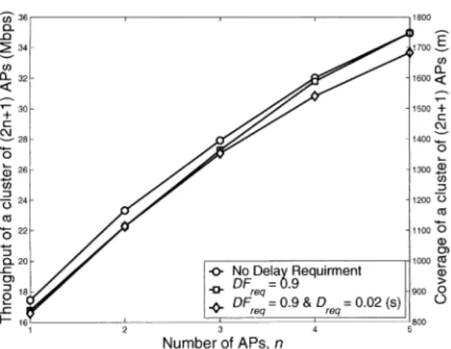
(m). It is true that these reception ranges vary for different environments. Nevertheless, the proposed optimization approach is general enough to evaluate the performances for different ITS wireless mesh networks by adopting various reception ranges.Figure 4 illustrates the capacity (total throughput) and coveragefor aclusterof(2n+1) APsunder different delay requirements. In the figure, n = 5 can achieve the optimal
capacity of 35 (Mbps) and coverage of 1748 (m) if without delay requirement. If setting the delay fairness requirement
DFreq
=0.9, theoptimal capacity and coverage foracluster remain unchanged for n = 5, while for n = 4 the optimal capacity decreases from32 to 31.8 (Mbps). Inaddition, one can observe that the delay requirement Dreq = 0.2 (s) canbe fulfilled at the expense that the optimal capacity for a cluster decreasesto33.7 (Mbps) witha coverageof 1683 (m)
at n = 5. In this figure, it is obvious that the more the number nofAPs, the better thecapacity and coverage ofa
cluster. However, the optimal solution is determined by the constraints on the linkcapacity, reception ranges, and delay requirements.
In Fig. 5, the overall frame delay DT(n) for the user in
the cell of
AP,
versusthecell radius ris shown. This figure shows that the frame delay canbe ensured by appropriately shortening the cell radius r. For example, the frame delaycan be dramatically reduced from hundreds of seconds to 0.1 (s), while the cell radius r merely decreases from 79.4
to 79.1 (m) at n = 5. In this ITS WMN, the phenomenon ofexcessive delay is due to the fact that the wireless relay link is fully utilized (especially for the link between
AP1
and
APO),
ifwithoutanydelay constraint. In themeanwhile,forPc, 1, the frame delay grows toward avery large value
[14], asshown in(26).However, byshrinking thecell radius and then the separation distance between APs to raise link-capacity, the delay performancecanbeimproved atthe cost
of lower capacity and coverage of a cluster as shown in
Fig. 4.
In Fig. 5, it is also shown that the maximum cell radius
r of each AP decreases if the number of n increases. In
this ITS wireless mesh network, the total throughput for
a cluster also increases while n increases, as illustrated in
Fig. 4. Forhandling the incrementofforwarding trafficas n
increases, the separation distance d between APs (and then the cellradius r)shouldbereduced toimprovetherelaylink L capacity. Due to the constraint on the cell radius as in (6),
i.e., r =d/2> rMIN, there will exista maximum value of
n.
In this example, the maximum allowable numberof APs3
Number ofAPs,n
Fig. 4. Capacity (totalthroughput) andCoverageforacluster of(2n+1) APs, underdifferentdelay requirement.
C 10' a) D 10 Co :3 10' a) 10 a)
20
a) 0 I I~~~~~~~~I
i I ~ ~ ~ n=41 -0- n= 1 1+~~~~~~~~~~~~--n=51 75 80 90 100 110 120 130 140 150Cell radius of each AP inacell,r(m)
Fig. 5. OverallframedelayDT(n)for theuserinthe cell ofAPnversus
the cell radius r.
in aclusteris na 5.
Figure 6 shows that theachieveddelay fairness indexDFI versusthe cell radius rof each AP. Oncan observe thatthe
delay fairness degradesas the cell radius r orthe numbern
ofAPs in acluster increases.Inthis ITSWMN,giventhe cell
radius r,thelargernwill causehighertrafficloadandlonger delay in the relay link between APs as shown in Figs. 4 and 5. Accordingly, the frame delay for the users in AP1,
AP2,
..., andAPR,
increase, while that for theusersinAPo
remainunchanged. Therefore, thedelay fairnessdowngrades
as n is increasing. In the same manner, the increment of r will also leadto higher delay in therelay link betweenAPs, thereby degrading the delay fairness.
VII. CONCLUSIONS
In this paper, we have investigated the access point placement problem for the ITS wireless mesh network. The
presentedmesh network architecture isappealingfor the ITS
applicationsdue to less cabling engineering work and lower infrastructure cost. An optimization approach to maximize the capacity and coverage for theconsidered ITS WMNhas been also presented.
In the presented ITS WMN, the frequency planning has
75 80 90 100 110 120 130 140
Cell radius of each AP in a cell, r(m)
Fig. 6. Achieved delay fairness index DFI versus the cell radius r of each AP.
been employed to effectively utilize the available multiple
channels. We have also proposed a PHY/MAC cross-layer
analytical mode toevaluate the delayand throughput of this ITS WMN. On top of the cross-layer model, the MINLP
optimization approach helps to analytically determine the
optimal number of APs in a cluster and the associated cell radius for each AP subject to the tradeoffs among delay,
throughput, andcoverage.
REFERENCES
[1] R. Pabst et a., "Relay-based deployment concepts for wireless and mobile broadband radio," IEEE Commun. Mag., vol. 42, no. 9, pp. 80-89, Sept. 2004.
[2] MeshDynamicswebsite,http://www.meshdynamics.com.
[3] R.C. Rogrigues,G. R. Mateus, and A. A. F Loureiro, "On the design and capacity planning of a wireless local area network," in Proc. IFEE/IFIPNOMS'00, pp. 335-348, Apr. 2000.
[4] M. Amenetsky and M. Unbehaun, "Coverage planning for outdoor wireless LAN systems," in Proc.IEEE Zurich Seminar on Broadband Communications,pp.49-1-6, Feb. 2002.
[5] M. Kobayashi et al., "Optimal access point placement in simultane-ous broadcast system using OFDM for indoor wireless LAN," in Proc. IEEE PIMRC'00,pp. 200-204, Sept. 2000.
[6] T.Jiangand G.Zhu,"Uniformdesignsimulatedannealing for optimal accesspoint placementofhighdata rateindoorwireless LAN using OFDM,"in Proc. IEEEPIMRC'03,pp. 2302-2306,Sept. 2003. [7] Y. Lee, K. Kim, and Y. Choi, "Optimization of AP placement and
channel assignment in wireless LANs," inProc. IEEE LCN'02, pp. 831-836, Nov.2002.
[8] J.-H.Huang, L.-C. Wang, and C.-J.Chang,"Deployment strategies of accesspointsfor outdoorwirelesslocal areanetworks,"in Proc. IEEE VTC'05,May2005.
[9] G. Bianchi, "Performance analysis of the IEEE 802.11 distributed coordinationfunction,"IEEEJ.Select. Areas Commun., vol. 18, no. 3, pp.535-547, Mar. 2000.
[10] X. J. Dong and P. Variya, "Saturation throughput analysis of IEEE 802.11 wireless LANs for a lossy channel,"IEEE Commun. Lett., vol. 9, no.2, pp. 100-102, Feb. 2005.
[I1] Y. C. Yay and K. C. Chua, "A capacity analysis for the IEEE 802.11 MAC protocol,"Wireless Network, pp. 159-171, Jul. 2001. [12] R. Jain, D. Chiu, and W. Hawe, "A quantitative measure of fairness and
discrimination for resource allocation in shared computer systems," Technical Report DEC-TR-301, Digital Equipment Corporation, Sept. 1984.
[13] CISCO, Cisco Aironet 1200 Series access point. [Online]. Available: http://www.cisco.com/en/US/products/hw/wireless/ps430/index.html [14] D. Gross and C. M.Harris,Fundamentals ofQueueingTheory, 3rd ed.
NewYork: JohnWiley& Sons, Inc, 1998.