Multipath fading effects on carrier recovery of
BPSK signal in digital radio
G.4. Liu, MSc C.-H. Wei, PhD
Indexing t e r m : Carrier recovery, Digital radio, B P S K , Intersymbol interference, Multipath fading
Abstract: Tracking performance of the
I-Q
carrier recovery loop for BPSK signal in band- limited channel with multipath interference is analysed. The multipath fading channel is charac- terised by the Rummler’s model (a simplified three-ray model) for line-of-sight digital radio system. A closed-form expression for the phase- error variance related to the multipath inter- ference, intersymbol interference and channel noise. is derived. Excess phase offset induced from the multipath interference is also examined. The closed-form expression of the jitter variance can be evaluated numerically to assess the degradation of synchroniser performance. Asymptotic limits of the performance are also discussed.
1 Introduction
Carrier recovery is crucial for coherent detection in digital communication systems. It recovers the carrier phase from noise-corrupted and severely interfered signals. The main impairments which degrade the per- formance of a carrier synchroniser are self noise, cyclic slipping, channel noise, intersymbol interference (ISI) and sometimes multipath interference. Among these impair- ments, the IS1 effects on the carrier recovery loop have been well discussed in the literature [l-61. Hinedi and Lindsey [6] have derived a closed-form expression for the phase error variance due to ISI. Most HF radio channels in which fading is encountered are basically line-of-sight (LOS) communication links with multipath components arising from secondary reflections, or signal paths from surrounding terrain. In such channels the number of multipath components is small, so the channel can be modelled by a two- or three-ray model [7]. The statistics of the model parameters for two or three rays can be determined empirically through the field measurement data. The properties of the three-ray propagation models are studied in References 14 and 15. Channel models based on three rays have been proposed in References 11 and 16-19.
In this paper, by using the simplified three-ray multi- path model (Rummler’s model [l l]), the statistical char- acteristics of the phase error for the
I/Q
carrier-recovery 0 IEE, 1993Paper 96831 (EE), received 25th January and in revised form 1st June 1993
The authors are with the Institute of Electronics and Center for Tele- communications Research, National Chiao-Tung University, Hsinchu, Taiwan, Republic of China
IEE PROCEEDINGS-I, Vol. 140, No. 5, OCTOBER 1993
loop in the multipath channel are obtained in several closed-form expressions. Asymptotic bounds of the per- formance and numerical examples in terms of the channel characteristics are also examined.
2 Formulation
A
BPSK
signal can be written in the following general form s(t) = J(ZP)m(t) sin (w,, t+
e)
(1) where m m(t) = akp(t -kT)
k = - mrepresents the data modulation on the signal after bandli- miting filtering. In eqn. 1, the carrier phase is denoted by 8, ak is chosen from symbol set {
+
1, - 1 ) with equal probability and p(t) = g(t) h(t), where*
represents the convolution operation. Here, g(t) stands for the signalling pulse and h(t) is the impulse response of the bandlimited channel. The signal encounters IS1 effects due to thebandlimitation.
In radio communications, the transmitted signal may be reflected by obstacles and the received signal is dif- fused with the reflected interferences from multiple paths. Owing to the frequency selective fading it will induce another source of IS1 on the received signal, in addition
to that by bandlimitation. Dispersion due to multipath propagation degrades digital transmission via the gener- ation of ISI. In this paper, these two different sources of
IS1 effects are considered simultaneously on the per-
formance of the carrier tracking loop for BPSK signal.A simplified three-ray model based on channel meas-
urement performed on microwave LOS radio channels has been proposed by Rummler [ll-131. The low-pass equivalent transfer function of the three-ray model with fixed delay parameters can be written
C ( j 0 ) = a{1 - Be-~(”-op)r} E 4 1 - BD(j41 (3)
where the frequencies w and oF are measured from the central frequency wo
.
In eqn. 3, parameter CI is the overallattenuation factor, /3 is a shape parameter due to the multipath component, wF is the angular frequency of the
This work was supported by the National Science Council, Republic of China, under grant NSC82-
0404-E009-122. The authors would like to thank
the referees for their valuable comments in
fade minimum (or referred to as notch frequency), and z is the relative time delay between the direct and the multipath components. The transfer function can be interpreted as the response of a channel that provides a direct transmission path with amplitude factor a and a
secondary path with relative strength
B,
at a fixed delay Tand a phase offset w P r
+
A at the central frequency (phase A results in a minus sign in eqn. 3). Note that eqn. 3 has the appearance of a two-path response. This response can be viewed as arising from three different paths. Among these three components, the direct path signal is unfaded, and the second path is similar in strength and close enough in delay to the first one such that their composite response is constant (here denoted by a). The third path at relative delay z and relative strength j? provides the frequency shaping of C(jo). The block diagram of the simplified three-ray model is shown in Fig. 1, whereWO)
can be viewedas
an allpass trans- fer function with linear phase &,(w) = -(U - o& andD(jw)=exp-j(w-wF,F)r
SimpI$ed three-ray model for multipath channel Fig. 1
flat magnitude response
I
D ( j o )I
= 1. Assume that theenvelope m(t) of the signal varies slowly, the output signal of the lower arm can be approximated by
(4) where T and T,, represent the group delay and the phase
delay o f D ( j w ) at the neighbourhood of carrier frequency coo, respectively.
rAt)
=
aS{,/(2P)m(t - re) sin (wo(t - T,,)+
e)}
Therefore, by using eqns. 4 and 5, the received signal at the channel output can be written
r(t) = a,/(2~)m(t) sin (ao t
+
e)
- a&/(2P)m(t - T )x sin(wot
+
+
e)
+
dt)
(6)The first term represents the signal component, the second term is viewed as the multipath interference and the third term is the channel noise. The channel noise n(t) considered here is a white Gaussian noise, expressed by
n(t) = ,/(Z)[n,(t) cos (ao t
+
cp) - nAt) sin (wo t+
cp)]where cp is the noise phase. The in-phase and quadrature components of the noise are assumed to be statistically independent, stationary white Gaussian noise processes with (two-sided) power spectral density N 0 / 2 watt/Hz.
These noise components can be rewritten from eqn. 7 as
(7)
dt)
= ,/(2)[N,(t) COS (w0 t+
e)
-
Ndt) sin (ao t+
e)]
(8)382
where
N,(t) = n,(t) cos (0 - cp)
+
n i t ) sin(e
- cp)(94
( 9 4 NXt) = -no@) sin
(e
- cp)+
n&) cos(e
-
cp)and
N,(t)
+
j N s ( t ) = In&)+
jns(t)]e-"8-P' (10)The quadrature components N,(t) and N J t ) have exactly
the same statistical characteristics as n,(t) and n#).
sign01 -
multipath
interference
Fig. 2 I Q carrier recovery loop for BPSK signal
A conventional maximum-likelihood (ML) phase- recovery loop for
BPSK
signal is shown in Fig. 2 [lo].The loop input is composed of the signal component, the multipath interference and the channel noise. The quad- rature reference signals generated from the voltage- controlled oscillator (VCO) can be written, respectively,
(1
14
( 1 Wwhere &t) and
K 1
represent the VCO estimate for the signal phase and the root mean square (RMS) value of the reference signals, respectively. In the usual way, the phase error is defined as(12)
which is assumed to be constant over each 7'-second interval. In the sequel, to make the problem mathematic- ally tractable, we assume that frequency offset is negligi- ble and only phase uncertainty is considered. By using eqns. 6, 8 and 11, the phase detector (PD) outputs in the
I / Q channels can be arranged into cos
4
and sin4
terms, neglecting the double frequency components, asby
rAt) = J ( 2 ) K 1 cos (wo t
+
&))rdt) = , / ( 2 ) K 1 sin (coot
+
&t))&(t) =
e
- &t)E&) = K , K , { a & / ( P ) m ( t
-
T) sin (-OW)+
N,(t)}x COS
4
+
K , ~ , { a J ( % O )-
abJ(P)m(t -4
x cos ( w p r ) -
N&)}
sin4
( 1 3 4d t ) = K,K,{a,/(P)m(t) - aS,/(P)m(t
-
r ) x COS ( w ~ T ) - N,(t)} COS4
+
K I K ,x {aB,/(P)m(t - T ) sin ( w ~ T )
-
N,(t)} sin4
(13b)
where K , is the gain of the loop multiplier, with dimen- sion V - ' . On the other hand, the respective signal at the
I/D filter output through a sample-and-hold (S/H) device IEE PROCEEDINGS-I, Vol. 140, No. 5, OCTOBER 1993
L . k = O - sin (wF T ) sin 4}
1
a, Qk f K I K m { ( a , / ( P ) T k = O?
a k l k -" )
I
x cos(4)
- N, sin4
whereThe noise responses N , and N , at the I / D filter output are independent Gaussian random variables with identi- cal variances u2 = N o T / 2 . The parameters L , and Li in eqn. 14 represent the memory lengths of the bandlimited channel with and without multipath effect, respectively. The quantities I, and Qk in eqn. 15 can be easily calcu- lated once g(t) and h(t) are known. The ower of the signal baseband pulse is unity, i.e. (1/T)
5
$(t) dt = 1. Inthe interval kT
<
t < (k+
1)T, the normalised dynamic error signal z'(t) at the input of loop filter can be expressed as+
t a Z / ? Z P T 2 sin ( 2 4+
2 0 , ~ )1
akQk( k T 0
>'
The low-frequency component (near DC) of z'(t) is extracted by the loop filter and used to adjust the phase estimate. By using linear model analysis [8-lo], we adopt the approximation sin 2 4 E 24*, the phase estimate at
the VCO output can be written as
where p is the Heaviside operator defined by p = d/dt
and K , is the gain constant of VCO with dimension rad/ s / V . Referring to Fig. 2, the system equation for the phase error is written as
2 p 4 = - 2 K , F(p)z(t) =
-
2K'F@)z'(t) (19)K' = K , ( K I K , ) Z (20)
with
where F(p) is the transfer function of the loop filter. Sub-
stituting eqn. 17 into eqn. 19, after some mathematical manipulation the loop equation can be rearranged as
2p4
+
K'PT2F(p)x(t, 2 4 ) sin 2 4 = K'F(p)N,(t, 2 4 ) (14b) ( 1 5 4 (21) where+
E'/?' cos (2wF z) a, Q, ( k T 0>'
- a2/?PT2 sin ( 2 4
+
(u.z)(3
a k l k ) (f
akQk)k = O k = O
and
N&, 2 4 ) = N:(t) cos 2 4
+
Nzt) sin 2 4 (23) withN",(t) = - 2 a / ? , / ( P ) T [ N , cos
+
N 2 sin m p r ]1
ak Qk( k T 0
)
+ 2 a B J ( P ) T [ N 2 cos w F z - N , sin mFr]
*
For practical cases, even if the phase error is in the region of n/3 or W, the PLL can be well treated as a linear system [20, p. 17J383 IEE PROCEEDINGS-I, Vol. 140, N o . 5, OCTOBER 1993
The term x(t, 2 4 ) conveys all the information regarding
the phase of the received signal. The terms
N&,
2 4 ) con-situting the channel noises and other impairments are referred to as equivalent noise. From eqn. 22, it can be
found that there are self noises induced from the random
x(t,
w).
Since these self-noise components are pro- portional to sin 2 4 , they can be neglected in the linear analysis for small phase error. As discussed in Reference14 the signal at the loop filter input can be approximated
by the expectation value of the term x(t, 2 4 ) over { a k } .
The effective signal amplitude is
terms (CaiIi)', (CakQd' and ( C a k I a U k Q t ) in
= PT2E[x(t, 2411 (25)
where E[x(t,24)] is assumed to be independent of the
time index
k.
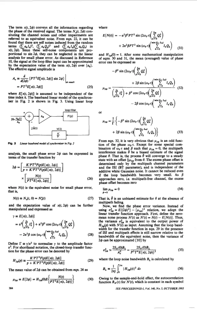
The baseband linear model of the synchron- iser in Fig. 2 is shown in Fig. 3. Using linear looploopfilter F(P) 2 9 + m n, Z e ( 0
I
F-
I
Fig. 3 Linear bawband model ofsynchronism in Fig. 2
analysis, the small phase error 2 4 can be expressed in
terms of the transfer function by
1
K'PT'F(p)E{x(t, 2 4 ) ) P
+
K'PTzFOE{x(t, 2 4 ) )2 4 = [
where N(t) is the equivalent noise for small phase error,
that is,
N ( t ) Ne@, 0) = NXt) (27)
and the expectation value of x ( t , 2 4 ) can be further
manipulated and expressed as
Define
r
I y/az to normalise y to the amplitude factora'. For shorthand notation, the closed-loop transfer func-
tion for the phase error can be denoted by
where
E { N ( t ) } = -a'b2PT' sin ( 2 0 , ~ )
CO
Q:)
mi. (Li. L d
(
zo
I k Q k ) (31)+
%z'BPT' sin (oF z)and H2+(0) = 1. After some mathematical manipulation of eqns. 30 and 31, the mean (averaged) value of phase
error can be expressed as -
8'
sin ( 2 0 p T)Q
:
( k r 0
)
From eqn. 32, it is very obvious that pl+ is an odd func-
tion of the phase o,z. Except for some special com- bination of O ~ T and
b
such that pz0 = 0, the multipathinterference makes
4
be a biased estimate of the signal phase 8. That is, the process8
will converge to a steady state with an offset $pa+ from 8. The excess phase offset is determined only by the multipath channel parameters and the IS1 (BT parameter), and is independent of the additive white Gaussian noise. It cannot be reduced even if the loop bandwidth becomes very small. As8
approaches zero, i.e. multipath-free channel, the excess phase offset becomes zero(34)
That is,
4
is an unbiased estimate for 0 at the absence of multipath fading.Now, we find the phase error variance. Instead of
using U:+ = E{(24)'} - {p1+}' relation, we adopt the linear transfer function approach. First, define the zero- mean noise process N'(t) as N ( t ) = N(t) - E { N ( t ) } .
Thus,
the variance U:, is equivalent to the output power ofH,+(p) with W(t) as input. Assuming that the loop band- width for the transfer function in eqn. 29 in the presence of IS1 and multipath effects is still narrow relative to the bandwidth of the equivalent noise, then the variance of
2 4 can be approximated [ l o ] by 2S,.(0)BL 2S,.(0)BL
U;+
=
2 =A , PZT4E{x(t, 24)}' (35)
K'PT'F(~)E{ x( t,
24)}
(29) where the loop noise bandwidth B, is calculated by
H2+@)
=
+ K'PT (p)(36) 1 J-
'F
E{x(t, 2 4 ) )The mean value of 2 4 can be obtained from eqn. 26 as B L - 2 n j
=-I
I
Hi&)1'
ds(30) Owing to the sample-and-hold effect, the autocorrelation
function
R&)
for"(0,
which is constant in each symbolperiod, can be written [6, l o ] A , = -2P3 sin 20,z sin W ~ T
-!$I
1 ~ 1
d T otherwise R”(T) =The Fourier transform of RN@) appears as S,.(W) = uf
j-y
(1 - d7with
(37)
(39) where the noise variance U$ is defined as the expectation value of the squared equivalent noise process N ’ ( t )
U $ E E{N”(t)} = E { N 2 ( t ) } - (E ( N ( t ) } ) ’ = a4B4P2T4 sin2(2wFz) 2
{
1
Q i - 21
Q: ( k T 0>’
k r 0}
min (Li. L,)+
4a4B2P2T4 sin’(w,?){( k = O1
I k Q k ) , - 2 rk = O5
L m ) I ~ Q ~ )+
(
k = Of
I:)( k = O QE)}-4a4B3P2T4 sin ( 2 0 ~ 5 ) sin ( 0 ~ 5 )
{
21
Q:( k r 0
)
(40)
where the expression for E { N ( t ) } is given by eqn. 31 and that for E { N 2 ( t ) } is derived in the Appendix. Thus, the variance can be rearranged as
where A = j4 sin2 20, T A, = 2B2 sin2 o F z I E E PROCEEDINGS-I, Vol. 140, N u . 5, O C T O B E R 1993
B2
A , = - P 1 A’
-7 - 2 p (42s)and p = a 2 P T / N o defines the desired signal energy to noise density at the loop input. The analytical result in eqn. 41 relates the jitter variance performance to the effects of bandwidth limitation and multipath inter- ference.
3 Asymptotic bound
Since the derivation of the analytic results in eqns. 32 and 41 is independent
of
the signalling pulse shape g(t), they become the analytical bounds for the performance of carrier recovery loop in the bandlimited multipath channel. The most significant point of these analytic results is that they relate the first- and second-order sta- tistical characteristics of the phase jitter to the impair- ments of ISI, multipath interference and channel noise.In eqn. 41, as signal-to-noise ratio p in the multipath
channel becomes large, the jitter variance becomes
mln (Li. L.)
+A,[( k = O
1
I k Q k ) , - 2(”‘”2””1:~:) k = O+
(
k = O2
I:)( k = o5
e:)]
+
A1[2( k = O2
Q:)
(43) where coefficients { A ; } are defined in eqns. 42u-c. That is, even in the higher signal-to-noise case, the jitter variance is not zero. There exists a residual jitter variance deter- mined by the IS1 components from selective fading and band limiting. Since the values of coefficients { A ; } are equal to zero as /3 approaches zero, thus the residual jitter variance in eqn. 43 is also zero in the extreme case.
Furthermore, as the factor
B
approaches zero, eqn. 41 becomes4 N 0 BL{ u2PT4( k = O I:>
+
+ N O T 3lim ci0 =
0 - 0 e4P2T4( k = O 1;)’
or expressed as a function of p by
The result in eqn. 44 is the same as developed in Refer- ence 6, where only IS1 due to band-limiting is considered. 385
The jitter variance, in this case, is determined by the IS1 and the channel noise. Furthermore, if an ISI-free channel is considered, the jitter performance becomes that in Reference 10 (p. 255),
(46)
In this case, it is obvious that the performance of the carrier recovery loop is dominated by the channel noise. 4 Numerical examples
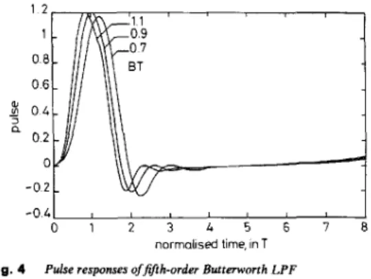
Without loss of generality, a fifth-order Butterworth low- pass filter is used as an example of the bandlimited channel. The IS1 effect caused by bandlimitation can be
controlled by the parameter BT, where E is the 3 dB cut-off frequency. Fig. 4 shows a family of pulse responses for such an LPF with BT = 0.7,0.9 and 1.1, respectively.
- 0 4 1
,
0 1 2 3 4 5 6 7 8
normabsed time, in T
Fig. 4 Pulse responses offifth-order Butterworth LPF BT
-
0.7,0.9, 1.1Once the multipath channel parameters are given by using the closed-form expression in eqn. 41 the jitter variance can be calculated numerically. Fig. 5 shows a numerical result of eqn. 41, normalised to loop parameter
4B,T, for a channel with severe fading, where the channel
is described by the following model parameters: 7 = 6.31 ns, a = 0.0322, f? = 0.9010,fF = 5.78 MHz* and 1 o3 "0 102 $ 10'
5
5
100 P%
E 10-1 ;ei
;
10'2 E 10 15 20 25 30 35 40 10 15 20 25 30 35 40 slgnal-to-noise ratio p ,dB Fig. 6 a = 0.0322, BT-
1.0,~ = 0.164T, I, = 5.78 MHz Numerical results for normalisedjitter varianceFitting parameters for measured fade in Reference 13 (Fig. 2) 386
ET = 1.0. The relative notch depth, E = -2Ol0gl0(l - f?) is 20.1 dB, the scale factor A = -20 log,oa, is 29.8 dB, and the notch frequency is 5.78 MHz above the central fre- quency. It is a severe fade both in shape and depth. In Fig. 5, to compare the effect of frequency selectivity, numerical calculation results for various values of f? are
also shown (f? = 0.7, 0.5, 0.3, 0.1, O.O), where f? = 0.0 rep- resents the case without multipath interference. The timing for the I/D filter is chosen at that the signal has minimum ISI.
The numerical results shown in Fig: 5 are obtained with deterministic channel parameters. However, these parameters are usually random in practice, thereby it will be more realistic to examine the result for random quant- ities. In general, given the joint statistical distributions of a, f? and w F , the expectation value of the loop per-
formance can be evaluated directly. For the sake of con- venience, variable transformations are taken to ease the mathematical manipulation. Here, we introduce the new random variables A, B and Y, which are related to the channel parameters a, f?, T and wF T by
A
=
-20 logloa 0<
a Q 1 E G -20 lOg,,(l-
f?) 0 Q f? Q 1Y
=
360f,t (47)Define pAsr(A, B, Y) as an arbitrary joint probability density function of A, E and '4'. Then the statistical aver- ages of U$ and p z , with respect to the channel statistics can be manipulated in a general form, respectively, by
z, = E[u$,] =
JJJ
pAIPY(A, B, Y)u& d A dB d" (48)sss
52 -
Pz, G Ebzml = PAIFY(A,
4 W P Z ,
d A d B (49)In fact, the probability density functions of the channel parameters for Rummler's model have been well recog- nised [l 11. Based on the statistics, an illustrative example for eqns. 48 and 49 is described in the following.
First, the choice of the parameter 7 in the fixed delay model is dependent on the channel bandwidth. In Refer- ence 11, the choice of T = 6.31 nsf provides the best fitting of the model from measurement data. The dis- tribution of the relative strength factor f? can be written in exponential form (1 - f?)z.3. The probability finding f?
between 0.0 and 0.5 is Prob (0.0
< <
0.5) = 0.79. Simi-larly, the probability Prob (0.0
<
f?<
0.7) is 0.94. That is, the small value of f? (less selective) occurs more frequent- ly. On the other hand, the overall attenuation factor a is characterised with lognormal distribution. The standard deviation of the distribution is approximately 5 dB for allf?. The mean of the distribution is dependent on the f?
factor. For f? > 0.5, the mean value is close to 25 dB. In contrast, for smaller value of f?, the mean value decreases to 15 dB. The probability density function offF = wF/2n is uniform at two levels and can be expressed as
t
In Reference 11, the radio channel was equipped with 8 PSK at a rate of 78 Mbit/s occupying 30 MHz bandwidth. To keep the consistency of this channel condition (statistics) for BPSK, in the illustrative examples, transmission at a rate of 26 Mbit/s in the same bandwidth is assumed so that T Y 0.164T(T: bit period for BPSK).where T is the fixed delay. Taking the variable transform- ation in eqn. 47, the statistical distributions of A, B and Y can be written, respectively, [12]
In fact, because pz4 is an odd function of Y (see eqn. 32) and the distribution of Y is even in [ - 180”,
+
180”1,&
is equal to zero.with
p, = 24.6(B4
+
500)/(B4+
800)In particular, the distribution of Y (or notch frequency) is independent of the other parameters. There exists dependence between parameters A and B as shown in eqn. 51, where the mean value of A , p A , can be expressed in a simple form of
B.
Although the distribution of A is dependent on the value of B, the dependence is limitedand may often be ignored [13]. Introducing eqn. 51, the expectation value of the jitter variance in eqn. 48 can be written by
oz -24 - - [ - ~ ~ h ’ ( y ) r p A ( A ) p d B )
x &(A, B, Y, T) d A d B d Y (52)
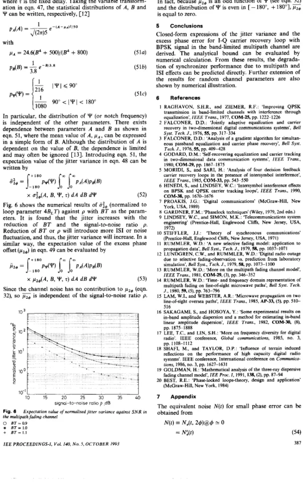
Fig. 6 shows the numerical results of (normalized to loop parameter 4B,T) against p with BT as the param- eters. It is found that the jitter increases with the reduction of BT and the signal-to-noise ratio p . Reduction of BT or p will introduce more IS1 or noise fluctuation, and thus, the jitter variance will increase. In a similar way, the expectation value of the excess phase offset (pzc) in eqn. 49 can be evaluated by
x p2+(A, B, Y, T) d A d B d Y (53)
Since the channel noise has no contribution to pz4 (eqn.
32), so is independent of the signal-to-noise ratio p .
.-
I J 3 t c U %s
100 E bh
1
-1
lo-’L
10 15 20 25 30 35 40 signal-to-noise ratio p ,dB Fig. 8the multipath fading channel
Expectation value of normalised jitter variance against SNR in
0 ET = 0.9
*
ET = 1.0+ ET = 1.1
IEE PROCEEDINGS-I, Vol. 140, No. 5, OCTOBER 1993
5 Conclusions
Closed-form expressions of the jitter variance and the excess phase error for I-Q carrier recovery loop with
BPSK signal in the band-limited multipath channel are
derived. The analytical bound can be evaluated by numerical calculation. From these results, the degrada- tion of synchronizer performance due to multipath and IS1 effects can be predicted directly. Further extension of the results for random channel parameters are also shown by numerical illustration.
6 References
1 RAGHAVON, S.H.R., and ZIEMER, R.F.: ‘Improving QPSK
transmission in band-limited channels with interference through equalization‘, IEEE Trans., 1977, COM-25, pp. 1222-1226
2 FALCONER, D.D.: ‘Jointly adaptive equalization and carrier
recovery in two-dimensional digital communications systems’, Bell Syst. Tech. J., 1976,55, pp. 317-334
3 FALCONER, D.D.: ‘Analysis of a gradient algorithm for simultan-
eous passband equalization and carrier phase recovery’, Bell Syst. Tech. J., 1976,55, pp. 409-428
4 GODARD, D.M.: ‘Self-recovering equalization and carrier tracking
in two-dimensional data communication systems’, IEEE Trans.,
1980, COM-29, pp. 1867-1875
5 MORIDI, S., and SARI, H.: ‘Analysis of four decision feedback
carrier recovery loops in the presence of intersymbol interference’, IEEE Trans., 1985, COM-33, pp. 543-550
6 HINEDI, S.. and LINDSEY, W.C.: ‘Intcrsymbol interference effects
on BPSK and QPSK carrier tracking loops’, IEEE Trans., 1990,
COM-38, pp. 1670-1676
7 PROAKIS, J.G.: ‘Digital communications’ (Mdjraw-Hill, New York, USA, 1989)
8 GARDNER, F.M.: ‘Phaselock techniques’ (Wiley, 1979,2nd edn.)
9 LINDSEY, W.C., and SIMON, M.K.: Telecommunications system
engineering’ (Prentice-Hall, Englewood Cliffs, New Jersey, USA,
1972)
IO STIFFLER, J.J.: Theory of synchronous communications’ (Prentice-Hall, Englewood Cliffs, New Jersey, USA, 1971) 11 RUMMLER, W.D.: ‘A new selective fading model: application to
propagation data’, Bell Syst., Tech. J., 1979, 58, pp. 1037-1071
12 LUNDGREN, C.W., and RUMMLER, W.D.: ‘Digital radio outage
due to selective fading-observation vs. prediction from laboratory simulation’, Bell Syst., Tech. J., 1979,58, pp. 1073-1100
13 RUMMLER, W.D.: ‘More on the multipath fading channel model’,
IEEE Trans., 1981, COM-29, (3), pp. 346-352
14 RUMMLER, W.D.: ‘Time- and frequency domain representation of
multioath fading on line-of-siefit microwave paths’, Bell Syst. Tech. J., 1980,59, ( 5 ) j p . 763-796
15 LAM, W.I., and WEBSTER, A.R.: ‘Microwave propagation on two
line-of-sight oversea paths’, IEEE Trans., 1985, AP-33, (5), pp. 510- 516
16 SAKAGAMI, S., and HOSOYA, Y.: ‘Some experimental results on
in-band amplitude dispersion and a method for estimating in-hand linear amplitude dispersion’, IEEE Trans., 1982, COM-30, (S),
pp. 1875-1888
17 LEE, T.C., and LIN, S.H.: ‘More on frequency diversity for digital
radio’. IEEE conference, Global communications, 1985, no. 3,
18 SHAFI, M., and TAYLOR, D.P.: ‘Influence of terrain induced
reflections on the performance of high capacity digital radio systems’. IEEE conference, International conference on Communica-
tions, 1986, no. 3, pp. 1627-1631
19 GOLDMAN, H.: ‘Mathematical analysis of the three-ray dispersive fading channel model’, IEE Proc. I, 1991,138, (2). pp. 87-94 20 BEST, R.E.: ‘Phase-locked loops-theory, design and application’
(McGraw-Hill, New York, 1984) pp. 1108-1112
7 Appendix
The equivalent noise N ( t ) for small phase error can be obtained from
N ( t )
=
N&,29)@4
U 0= N:(t) (54)
and
+
2aB,/(P)T(NZ cos (0,~)Note that N , and N , are two independent noise pro-
cesses with zero-mean and identical variance u2. Per- forming the expectation operation on the squared equivalent noise, obtains
E{N2(t)}
= a 4 p P 2 T 4 sin2(2u,r)
- 4a4B3p2T4 sin ( 2 0 , ~ ) sin (0,~)
388
+
4a4BZPZT4 sin3(w,r)+
4 a Z B Z P T 2 E { [ N z cos (mor)+
N,
sin (00r)]2}x E { [ N , cos (U,?) - N , sin
(0,412}
+
4 E { N : } E { N $ } (56)By using the following relations,
E{N:} = E{N:} = U , (57)
= 6kl (58)
where 6,, denotes the Kronecker delta function, the
higher-order moment
E{ak a, a,. a,} = 6,,
ak.,
+
6,.all.
+
61,. - 2ak1 6k.r. (59)we obtain
Combining eqns. 56-62 and 31, the final formula in eqn.
40 is obtained.