Configurable Platform-based Power Management Schemes on the
Embedded Tablet System
HUNG-MING CHEN
1, PO-HUNG CHEN
1, SARANGEREL DORJGOCHOO
2, TAI-JEE PAN
3and
FEIPEI LAI
1,2Dept. of Electrical Engineering
1& Dept. of Computer Science and Information Engineering
2National Taiwan University
No.1, Sec. 4, Roosevelt Road, Taipei 106
Center for Research of Advanced Information Technologies (CRAIT), TATUNG Company
322, Chung Shan N. Rd., 3
rdSec, Taipei 104
TAIWAN
E-mail: simonc@orchid.ee.ntu.edu.tw
Abstract: - A power-aware embedded tablet appliance has been presented, which belongs to the handheld devices of 8.4 to 15 inches medium to large display sizes for versatile pen-based wireless computing applications such as home control and industrial automation. Power consumption is as important a design criterion as performance on such portable systems. Unlike personal computer (PC) system with standard power management/control mechanism, the embedded system requires customization and hardware/software co-design on the power management mechanism. A configurable platform co-design for power management has been proposed to enable flexible power schemes on designing different user scenarios and application domains. In this paper, the design methodology for a platform-based power management on the embedded tablet has been explored. The methodology considers from the circuit design stage to dynamic power management with various hardware/software co-design issues. Then, a tablet appliance has been developed as an example to illustrate the configurable platform-based power management/control schemes. Furthermore, an implementation on an embedded operation system (OS) with advanced power management software shows the feasibility of this design. Finally, several additional features are proposed including collaborating embedded controller with configurable devices power control and the hot-swappable battery capabilities.
Key-Words: - Power management, Embedded system, Handheld, Tablet
1 Introduction
The demand for networked embedded handheld devices is large and growing rapidly. Its applications are widespread from work needs to family and personal leisure use. Hence, the embedded handheld devices emphasizing on the design of lightweight, thin, easy to use, portable, connectable, low power and dedicated purpose devices such as personal digital assistance (PDA), portable media player (PMP), multi-media mobile terminal and tablet appliances, which are capable of performing data process, communication, multimedia or Internet connection, are becoming mainstream.
It is known that, designing a multimedia and network-enabled embedded handheld device with highly integral chip, high performance CPU, large screen, high-resolution display and wireless-connected capabilities is considerably power demanding. Since it will greatly affect the usage
time for the users to operate these applications, the design for low power system becomes the main consideration on those devices.
The scopes of low power system design are quite comprehensive, consisting of integrated circuit (IC) process technologies, computer-added design (CAD) tools, memory system design, batteries, circuits, software designs and so on. According to the previous researches, power management design of the system level can achieve the best energy-saving effect.
In a whole platform design for the system power management, most of recent researches address on techniques at a specific stage. For examples, some researches discuss the power management at the run-time stage by CPU speed-setting [3], dynamic voltage scaling [4-6] and battery management [7-11]. For example, there are many CPUs provided with speed-setting and voltage scaling no matter in PCs or embedded systems, e.g., Intel Pentium processors
with SpeedStep technology, Transmeta Crusoe processors with LongRunTM technology, Intel
XscaleTM and AMD AlchemyTM CPU with dynamic
voltage and frequency scaling capability, and AMD IA-on-chip SC3200TM with clock throttling
capability. These techniques dynamically adjust the speed levels based on the performance and power consumption when the device is on duty. The key point lies in reducing the power consumption under the condition of conforming to the performance required by the user. Furthermore, some researches consider low power design for key components such as CPU, memory system [13] and battery [14].
To design an embedded handheld platform from scratch, the design techniques of system power management are required on both SW/HW co-design from co-design to system run-time stages. Although the platform usually is designed to satisfy the functionality of the required specification and reach the maximum performance, it is not necessary to always achieve the maximum performance. For example, when a user is just checking the contact list from the PDA, The system actually does not need the highest CPU speed or network connection. If we can set the idle component into low power state, then the system power can be greatly saved. Hence, dynamic power management is to reduce the power consumption by dynamically adjusting the component power state when the system is executing its workload.
Usually systems with dynamic power management [12][14][15][17] are provided with the characteristic of changing the power state of the system components based on the performance requirement of the system. Components can transfer between active and low power states depending on the power consumption and the transition time. Therefore, dynamic power management requires intensive considerations of HW/SW co-design. The components and related circuits must support the control of components in different power states, and the software controls the state transition according to system run-time status.
In addition, there exist some problems to implement dynamic power management in embedded operating systems. One of the most important issues is whether the operating system supports the built-in power management ability. In early days, APM [19] was used mainly in BIOS. Recently ACPI [20] has standard interface implemented on Windows operating systems. However, these standards are incomplete in those
small-footprint embedded operation systems. Thus there still exists considerable room to improve this part.
In this paper, a hardware (HW)/software (SW) co-design methodology is considered to apply for a platform-based power management from the circuit design stage to run-time dynamic power management stage. And, an embedded tablet system has been presented as an example to design as an assessment platform for various power management mechanisms. This embedded tablet system can serve for many consumer and commercial markets with different domain applications such as wireless remote display for desktop PC, home control, portable Kiosk, and inventory control for industrial automation. Thus, from power management point of view, a configurable architecture on such platform is required to fulfill different usage models controlled by users or software. Furthermore, unlike personal computer (PC) system with standard power management/control mechanism, this embedded tablet system requires customization and hardware/software co-design on the power management mechanism. An implementation on an embedded operation system (OS) ― Windows CE with advanced power management software shows the feasibility of this design. Several additional features are proposed including collaborating embedded controller with configurable devices power control and the hot-swappable battery capabilities.
The remainder of the paper is organized as follows. Section 2 presents the overall design of a configurable platform-based power management on embedded tablet system. Section 3 shows some experiment results about how this platform can be an assessment platform for power management schemes. Conclusions and future work are provided in Section 4.
2 Designing Configurable
Platform-based System Power Management
The design and features of a platform-based system power management using a wireless embedded tablet platform are developed. The goal is to build up an assessment architecture of system power management for the tablet type platforms, and utilize the embedded OS architecture like Microsoft Windows CE.NET [1] architecture to establish a power management system to satisfy the user’s requirement with different user scenarios.This embedded tablet belongs to the market of 8.4"-15" median sizes display devices, and mainly
applies to consumer market such as home control or portable network media display. In addition, it can be also applied to commercial markets for industrial automation, education, medical equipment, retailer or offices market segments.
The process of design methodology for platform-based system power management is illustrated on the smart tablet appliance as follows.
2.1 Designing the architecture of a wireless tablet appliance
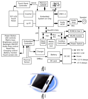
Fig. 1 depicts the hardware block diagram of a tablet appliance system and the appearance of this tablet device. The architecture of this smart tablet appliance that addresses the low-power related design is described as follows.
‧ Embedded Processor: AMD system on chip GeodeTM SC3200 [2] consists of x86 compatible
CPU core, integral display interface, north bridge chipset and a part of Supper I/O functions. The speed can be up to 266MHz with the capability of clock throttling for reducing power dissipation. ‧ Boot ROM: Onboard 2Mbits flash stores the boot-loader. Its firmware is implemented with APM-like supports. APM-like functions use special customized functions collaborating embedded controller to generate system management interrupt (SMI) instead of standard APM call not supported in embedded OS. Thus, embedded OS can leverage APM functions to achieve advanced power control without using standard BIOS call.
‧ Display interface: non-interlaced 16bpp TFT LCD with cold-cathode fluorescent lamps (CCFL) in LCD back-lighting inverter.
600 800×
‧ Programmable Embedded Controller (EC): This EC supports the functions including matrix keys, general purpose I/O (GPIO) buttons, System Management Bus (SMBus) [18] access interface, charge control interface, LEDs control interface, PWM based TFT LCD brightness control and backlight ON/OFF interfaces, legacy peripherals audio amplifier control interface and power management mechanism collaborated with system.
‧ Smart battery Pack: The smart battery pack consists of battery control board and several battery cells with serial and parallel connections depending on power requirement on the system. Using smart battery, it can supply with the capabilities of recording battery type, capacity, voltage dynamic range, maximum charge/discharge current, battery part number, temperature characteristic, and self-discharge
current. In addition, battery status is also recorded such as abnormal temperature, charge counts and the residual capacity. The above values are accessed via SMBus.
The typical power consumption of the key components on this platform is observed in [16]. Note that CPU is not the most power-consuming parts, but the display and communication parts, where LCD and Inverter account for about 1/3 power consumption. The advanced dynamic power management mechanism through the Microsoft Windows CE.NET platform is taken as the real case study as follows.
Embedded System on Chip
Memory
SDRAM Flash (OS)Compact
Audio AC97 USB 1.1
Power Switch Boot
ROM ControllerCardbus Power Button
LED controls Matrix keys Brightness control Backlight ON/OFF Audio Amp control
Reset Key Charging control
Battery monitor Touch screen intr.
Thermal Sensor LVDS Inverter Charger WLAN module TFT LCD Touch Panel PCMCIA Slot 1 Embedded Controller DC-DC Touch Panel Controller Audio Amp MIC Speaker Bus(PCI/ISA) SMBus ISA LPC IDE Battery DC Jack + 3.3 V always VCC 3.3V +5 V always VCC 5V Vcore Serial PCI Media proce-ssor Mini-PCI (a) (b)
Fig. 1. (a) Hardware block diagram of a tablet appliance system; (b) The appearance of a tablet device.
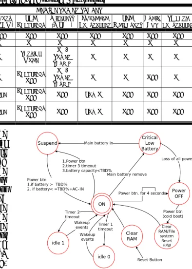
2.2 Defining system power states and transition
The methodology of defining the power states and transition diagram is presented. Besides the system enters suspend or OFF mode, the platform should be capable of defining more power states to adjust dynamically. Thus, additional states are defined (Fig. 2) according to the requirement. There are two idle modes defined in addition to suspend and OFF modes. The costs of any state transition including transition time and energy have to be taken into consideration.
All power states of system and major components are defined in Table 1. In the Suspend mode the system has to keep memory data, hence besides the embedded controller (EC), which controls the power
button and battery states, SDRAM and CPU will be moved into the low power state, the other peripheral components will be shut down. As for the two idle modes, the idle time can be defined, and which components will enter low power mode can be selected based on the usage modes. For example, to dim or shut down the backlight of display, shut down the speaker, or slow down the CPU is based on the system workload. In addition, some peripheral devices like wireless LAN module can be switched to low power mode, which time-out time with Access Point can be assigned to communicate if there are packets to deliver. Usually users can wake up the system with reaction time of around 0.5 second by pushing button or touching the touch-screen. By configurable setting of idle mode for components, it can be collaborated with use mode to achieve low power effect. For example, if users are listening to music, the system can shut down the backlight, or shut down the audio part when he/she is reading documents, etc.
2.3 Design of the advanced software power management on embedded OS
Just as the aforementioned, dynamic power management needs HW/SW co-design, meanwhile the supporting ability of power management is quite significant. Just like other embedded operation systems, Windows CE.NET does not support APM/ACPI power management system as in general windows systems. Its subsystem architecture of power management defines three major power states, ON, Suspend to RAM and IDLE. Designers can customize and extend the power states based on the platforms.
Power OFF Suspend CriticalLow
Battery
ON
Main battery remove Main battery in 1.Power btn 2.timer 3 timeout 3.battery capacity<TBD% Power btn 1.if battery > TBD% 2. if battery< =TBD%+AC-IN
Power btn. for 4 seconds
Loss of all power
idle 0 idle 1 Timer 2 timeout Timer 1 timeout Wakeup events Wakeup events Power btn (cold boot) Reset Button Clear RAM Clear RAM/File system Reset H/W Table 1
The comparison table of each system power state
DEVICEPOWERSTATES
LCD BACKLIGHT
WIRELESS
(WLAN)
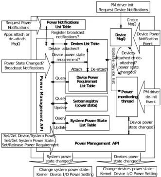
Fig. 2. State diagram of system power transition. Fig. 3 depicts an example of the architecture and flow of the power management driver. The power manager can dynamically attach/unattach power states supported by each device. The power states supported by each device are registered to Device Power Requirement List Table. The application software in the upper layer can register through the power management application program interface (API). The power manager will monitor each component through power monitoring thread, and broadcast to inform the driver of each component and the registered application software when the state has been changed.
2.4 Designing configurable devices power management control schemes
To support the control of configurable platform-based power management, we propose the ways for the embedded controller collaborating the system to achieve the following goals: (1) Controlling power
STATES DESCRIPTION (SC3200) CPU (SDRAM)MEMORY CEMBEDDED
ONTROLLER LED INDICATORS AUDIO AMP PC CARD CONTROLLER
OFF ALL POWER REMOVED OFF OFF OFF OFF OFF OFF OFF OFF
ON NORMAL OPERATION ON ON ON ON ON ON ON ON IDLE0 USER DEFINED -REDUCED
POWER LEVEL ON/THROTTLING ON
PARTIAL MODE ON/ POWER SAVING ON ON ON ON IDLE1 ON/ USER DEFINED -POWER
SAVING LEVEL ON/THROTTLING ON
BACKLIGHT
OFF SPOWER
AVING
ON ON OFF ON
SUSPEND SYSTEM SUSPENDED AND
DEVICE IS NONFUNCTIONAL DEEP SLEEP IDLE
BACKLIGHT
OFF OFF LOW ON OFF OFF OFF
CRITICAL LOW
ONLY BACKUP BATTERY AVAILABLE TO KEEP RAM
INTACT
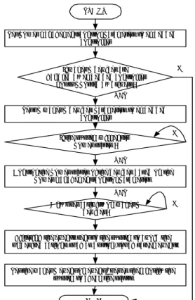
states of the respective devices controlled by embedded controller or an on/off of a power supply in accordance with the platform, (2) Recording, detecting and processing the devices generating wakeup events for each power state.
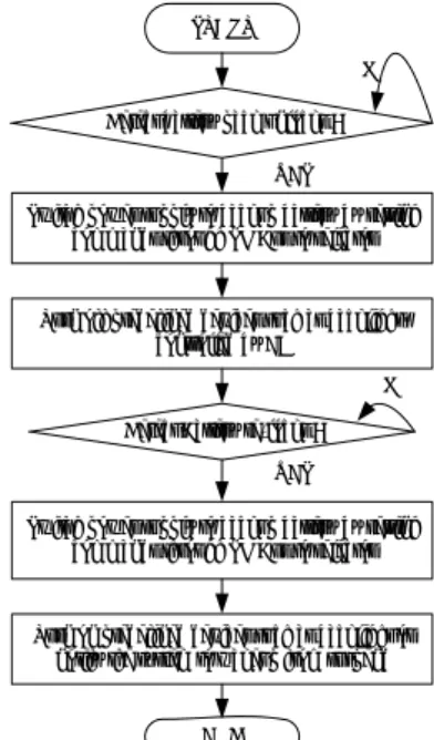
A procedure of this power management control is described with reference to a flowchart of Fig. 4. When the power management control system of embedded controller is started, the system can set up the parameters to configure power states of each device connected to the embedded controller. For examples, set brightness level to half of max value when in idle 0 state, set audio amplifier to mute and turn the LCD backlight to off when in idle 1 state. Then, the system can configure the wakeup devices for each power state that is not supported by operating system but connected to embedded controller. For examples, the system can set touch screen, buttons, PCMCIA card insertion to wake up the system on idle states, and configure the power button or DC-in to generate the resume event to wake up the system from suspend state.
Next, when the system goes through the various power states with the setting from operating system or external event like power button or battery unlock to embedded controller, the embedded controller will control the power states of each device by previous parameters setting.
The embedded controller keeps polling the wakeup events from the devices configured by previous setting. Once the user has an activity on those devices, the embedded controller will firstly filter the events sent to the system to avoid undesired actions such as the button events or touch screen events. This step can avoid the wrong actions, for example, if a user taps the touch screen when the LCD backlight is off on idle 1 state. Secondly, the embedded controller can set the event queues to notify the system to check the status then process the steps to wake up from previous power state.
2.5 Dual battery design for Hot-swappable battery capability
Due to the limitation of battery lifetime, in addition to keep enhance the dynamic power management of the system, a design of a configurable battery management mechanism is also proposed to make wireless tablet users can hot swap a new battery without turning off or suspending the system. This function will resolve the problem when a user working on urgent tasks requires the system to keep working the tasks even swapping the battery without any interruption or restarting the tasks.
Fig. 5 shows the hardware block diagram for controlling the platform with battery hot-swappable capability. Embedded controller acts as detecting the hot-swappable events, controlling the battery selector to switch between backup battery and main battery, and monitoring two battery statuses. The charger is in charge of charging two batteries and the default policy is charging sub-battery first then main battery. But, its charging policy still can be controlled by embedded controller through commands from SMBus for different usage scenario. Backup battery is designed to have the same voltage level otherwise additional circuitry is required for supplying voltages to DC-DC converter. The charge/discharge currents will be 1C (1 Amp) that is 2 times of main battery. For examples, if the main battery pack is 2S2P Li-Ion battery cells then we can design the backup battery to 2S1P Li-Ion battery cells. In addition, system controls can set the parameters about the power states of respective devices connected to controller during battery swapping, control the batteries charging policy, and monitor the events.
Fig. 6 illustrates the execution flow of this control mechanism about hot-swappable battery. When the battery management procedure is started, it will check the configuration to detect if the battery back unlock switch is open. If the user opens the switch, this procedure sets the commands through
Device MsgQ Power monitoring thread Devices attached or de-attached? power state changed? PM driver init Request Device Notifications
System Power State List Table Power Notifications List Table Create MsgQ Apps attach or de-attach MsgQ U pd at e d ev ic e lis t Device attached? Register broadcast notifications? P o w e r M a na g e m e nt A P I
Power Management API Devices List Table
System registry (power state) Query Update Device Power Requirement List Table Attach De-attach Query Update System power state changed? Change system power state: Kernel Device I/O Power Setting
Devices power state changed? Change devices power state: Kernel Device I/O Power Setting
Device power state changed? Query
Device power state requirement? Device Power Notification Event PM driver de-init Event
Set/Get Device/System Power, Set/Get System Power State, Set/Release Power Requirement
Power State Changed? Broadcast Notifications Request Power
Notifications
Fig. 3. The example of power management architecture on embedded OS
SMBus to battery selector. The selector switches the battery from main battery to sub-battery. Then, according to the configuration from system controls or default value if system controls do not set the related parameters, it will turn off or lower the power states of the devices connected to the controller to reduce the loading of sub-battery. For example, it turns off the backlight of LCD and amplifier of audio device. After that, the power supply is taken over by sub-battery. Once the user swaps the new battery then locks the battery switch, the controller switches the power supply to main battery by setting commands.
STA R T
If w ak eu p d ev i ces are h an d l ed b y emb ed d ed co n t ro l l er
n o t s u p p o rt ed b y d ri v ers ?
Set u p w ak eu p d ev i ces p aramet ers t o emb ed d ed co n t ro l l er E N D YES YES If t h e s y s t em w i l l en t er p o w er s t at es ? A n y u s er act i v i t y o n w ak eu p d ev i ces ? Fi l t eri n g t h e ev en t s s en t t o t h e s y s t em t o av o i d t h e u n d es i red act i o n s s u ch as b u t t o n , t o u ch s creen ev en t s
YES
Set p o w er man ag emen t / co n t ro l p aramet ers t o emb ed d ed co n t ro l l er
NO
NO NO
C o n t ro l t h e p o w er s t at es o f t h e d ev i ces b as ed o n t h e p o w er man ag emen t / co n t ro l p aramet ers
Set t h e w ak eu p ev en t o n ev en t q u eu es t h en n o t i fy t h e s y s t em t o ch eck t h e s t at u s
Fig. 4. A procedure of configurable device power management control.
Several criteria can be added to this control, e.g. if the battery capacity of sub-battery is too low, the controller can notify the system to suspend mode then wakeup after the new battery is installed. For future extension, with this platform design for dual batteries, it can be used for dynamic battery management in the future. That means the batteries can be switched dynamically based on different loadings to enhance the battery life [7].
3 Experimental Results
3.1 Experimental setup
The devices under test were: Embedded tablet board with 802.11b/g Wireless Local Network (WLAN), access point, gas gauge interface board and PC. Fig. 7 illustrates the experimental environment. The gas gauge interface and software provides connections for the communication lines of a smart battery with a serial interface port of a Windows-based PC. It can measure values of the discharge current, temperature, and voltage and let us calculate the power consumption of the system supplied from battery.
Fig. 8 shows the screenshot of the advanced power management program based on Windows CE.NET. Users can set two idle timers and select which devices to be shut down. ″Audio Amp″ option is used to disable audio feature when the device is in idle mode; ″CPU throttling″ option is used to select the desired CPU speed; ″Backlight″ option is used to to turn off the touch panel backlight; and, ″Brightness″ option is used to adjust the touch panel brightness.
3.2 Experimental Data
In Table 2, one ON mode, two defined IDLE modes and suspend mode are observed, where in IDLE 0 mode, backlight brightness reduces to its half as well as in IDLE 1 mode, backlight is turned off and
CPU speed throttled to 33MHz. Table 2 shows the system power consumption in each mode. It shows that the power will be saved about 10% in IDLE 0 and 47% in IDLE 1. In addition, as shown in Table 3, we also observe the system power consumption for turning ON/OFF WLAN module and enabling the power saving setting of the WLAN module. It shows that about 10% power saving with power saving mode enabled.
Charger Em bedded Controller SMBus Battery DC Jack Selector Backup Battery SMBus DC-DC Varioussupply voltages Battery Pack unlock/lock System controls
Fig. 5. Block diagram of controlling the platform with battery hot-swappable capability.
4 Conclusions and Future Work
A platform with configurable power management schemes can provide the flexibility for software integrator to apply for different operating systems
and different usage scenarios. In this paper, platform-based system power management techniques on a wireless embedded tablet system are explored. The proposed methodology has been used to implement a real platform from the platform design to power states definition. In the same time, we show that how this HW/SW co-design methodology applied on the embedded OS like Windows CE.NET as the advanced power management software to control the different power schemes. SM B u s In ter fa
ce Read/write the gas gauge registers and monitor the battery's status Ser ial I n te rf ac e Microcontroller (with SMBus access
interface) Gas gauge interface board Embedded Tablet Platform with WLAN Access Point
Fig. 7. Experimental environment.
START
Detect battery pack unlocks ?
Switch power supply to backup battery by setting commands through SMBus to selector
Turn off predefined devices such as backlight. controlled by EC
Detect Battery re-locks ?
Switch power supply to backup battery by setting commands through SMBus to selector
Turn on predefined devices such as backlight or notify the system to wakeup from suspend
END YES
YES NO
NO
Fig. 6. The execution flow of this control mechanism about hot-swappable battery.
The proposed architecture of embedded controller as the co-processor explains how to collaborate the platform to make the power management/control of the system to be configurable. This scheme with embedded controller is OS independent that has applied to i.e., Windows XP embedded and embedded Linux as well.
The experimental results show that the advanced power management has remarkable power saving effects. Hence, the software integrator can dynamically configure different power schemes of this platform through software to enhance the battery life. In addition, the experimental results show that the advanced power management has remarkable power saving effects. Hence, the software integrator can dynamically configure different power schemes of this platform through software to enhance the battery life.
In the future more advanced power management schemes are to be developed such as through not only system-based but also user profiles. In addition,
the battery-driven design such as dynamic battery control and management is in progress to enhance the batter life of the system.
Fig. 8. The screenshot of advanced power management program on Windows CE.NET.
References:
[1] Microsoft Corporation, Microsoft Windows CE.NET with Platform Builder 4.2, 2004.
[2] AMD, "Geode SC3200 Integrated Processor,"
http://www.amd.com/us-en/ConnectivitySolutions/ProductInformation/0, ,50_2330_9863_9899,00.html
[3] Martin, T.L.; Siewiorek, D.P, "Nonideal battery and main memory effects on CPU speed-setting for low power," IEEE Transactions on VLSI, Volume: 9 Issue: 1, Feb. 2001 Page(s): 29 –34. [4] T. Simunic, L. Benini, A. Acquaviva, P. Glynn,
G. De Micheli, "Dynamic voltage scaling for portable systems, " DAC 2001.
[5] D. Rajan, R. Zuck, C. Poellabauer, "Workload-Aware Dual-Speed Dynamic Voltage Scaling, " 12th IEEE International Conference on Embedded and Real-Time Computing Systems and Applications, pp. 251-256, 2006.
[6] H. Saputra, M. Kandemir, N. Vijaykrishnan, M. J. Irwin, J. S. Hu, C-H. Hsu, and U. Kremer. "Energy-conscious compilation based on voltage scaling," In Proc. ACM SIGPLAN Joint Conference on Languages, Compilers, and Tools for Embedded Systems and Software and Compilers for Embedded Systems, Berlin, Germany , June 19-21, 2002.
[16] H.-M. Chen, P.-H. Chen, T. -J. Pan and Feipei Lai, "Design and Features of Platform-based System Power Management on a Smart Tablet Appliance," The 10th
IEEE International Conference on Electronics, Circuits & Systems, 2003.
[17] E.Y. Chung, L. Benini, A. Bogliolo and G. De Micheli, "Dynamic power management for non-stationary service requests," IEEE Transactions on Computers, pp. 1345- 1361, Volume: 51, Issue: 11, Nov 2002.
[7] L. Benini, G. Castelli, A. Macii, E. Macii, R. Scarsi, "Battery-Driven dynamic power management of portable systems," IEEE International Symposium on System Synthesis, pp. 25-30, Madrid, Spain, September 2000.
[18] SBS Implementers Forum, System Management Bus (SMBus) Specification Revision 2.0, Aug. 3, 2000.
[8] D. Rakhmatov, S. Vrudhula, " "
Energy management for battery-powered embedded systems, ACM Transactions on Embedded Computing Systems, v.2 n.3, p.277-324, Aug. 2003.
[19] Intel Corporation, Microsoft Corporation, Advanced Power Management (APM) BIOS Interface Specification Revision 1.2. Feb. 1996. [20] Compaq Computer Corporation, Intel
Corporation, Microsoft Corporation, Phoenix Technologies Ltd., Toshiba Corporation, Advanced Configuration and Power Interface Specification Revision 3.0a. Dec. 30, 2005. [9] L. Benini, G. Castelli, A. Macii, R. Scarsi,
"Battery-Driven dynamic power management," IEEE Design and Test of Computers, Vol. 18, No. 2, pp. 53-60, April 2001.
[10] P. Rong, M. Pedram, "Battery-Aware power management based on markovian decision processes," Proceedings of International Conference on Computer Aided Design, Nov. 2002.
[11] Rong and M. Pedram, "Battery-aware power management based on markovian decision processes," Proceedings of International Conference on Computer Aided Design, Nov. 2002.
[12] M. Pedram and J. Rabaey, Power Aware Design Methodologies. Kluwer, 2002.
[13] D. Mossé, N. AbouGhazaleh, B. R. Childers, R. G. Melhem, "Energy Conservation in Memory Hierarchies using Power-Aware Cached-DRAM, " Power-aware Computing Systems, 2005.
[14] C.-H. Hwang and A. Wu., "A predictive system shutdown method for energy saving of event-driven computation," Proceedings of the Int.l Conference on Computer Aided Design, pp.28-32, 1997.
[15] G. Paleologo, L. Benini, A. Bogliolo and G. D. Micheli.," Policy optimization for dynamic power management," Proceedings of the Design Automation Conference, pp.182-187, 1998.
Table 3
The power consumption of system with wireless module being shut down or in power saving mode
Current A (mA)
Power (mW) =V×A (V=16Volts)
POWER STATES Max Min Max Min
ON mode with WLAN OFF 511 450 8176 7200 ON mode with WLAN ON 590 524 9440 8384 ON mode and WLAN in power saving mode 534 471 8554 7536 Table 2
The comparison table of each system power state
POWER STATES Voltage
V (Volts) Current A (mA) (W)=V × A Power
ON mode 11.104 755 8.38352
Idle 0 mode (Backlight - Partial mode: 50%of max;
CPU Speed: 266MHz) 11.104 683 7.584 Idle 1 mode (Backlight – OFF mode, CPU throttling to 33MHz) 11.104 401 4.452 Suspend mode 11.104 16 0.177664