延伸正規方法SpecTRM-RL以進行安全分析
8
0
0
全文
(2) 的,我們建議應該增加斷言(assertion)[11] [13] 即變數間的關係式。 本研究的目的針對電腦控制系統或嵌入 式系統,延伸 SpecTRM-RL 方法,使其可進 行進一步安全驗證。我們的方法包括以下步 驟:. (a) 系統圖. 1.根據 SpecTRM-RL 模型建構狀態轉換圖 2.根據 SpecTRM-RL 模型畫出 UML 時序圖 3.畫出增添式狀態轉換圖(augmented state transition diagram) 4.延伸 SpecTRM-RL 成為增添式 SpecTRM 模型(augmented SpecTRM model) 5.系統化的建構故障樹 6.以 UML 時序圖表達故障情境 (b) 限制定義 Output Command AND/OR Table. Output Device State AND/OR Table. 我們的方法延伸 SpecTRM-RL,應用 UML 時序圖可提升 SpecTRM-RL 的可讀性並明確 表達出子系統/元件間之互動;增添式狀態轉 換圖增加了錯誤的狀況,有利於驗證,能有系. (c) AND/OR表. 圖1. 統的分析出可能的不安全情境。. 二、相關背景研究. SpecTRM [12]. 2.2 故障樹(Fault Tree) 故障樹分析(Fault Tree Analysis)是一種. 2.1 SpecTRM. 廣泛使用在飛航、核能、電子工業的系統安全 SpecTRM[12] (Specification Tools and. 分析方式,目的在於分析造成危險及危害的原. Requirements Methodology)是 Leveson 根據她. 因。它由一不安全的事件往前推導其原因,而. 的 Intent Specification[7]的規格架構來發展的. 原因間使用 AND、OR 閘來表示造成危險原因. 一 套 軟 體 規 格 工 具 及 方 法 論 。 而 Intent. 的組合至元件層次,其示意圖如圖 2 所示。長. Specification 則是一套完整的軟體規格架構,. 方形為可展開的事件,菱形為不再展開的事. 它分為 7 層(levels)包含高層級的需求和安. 件,圓形為終結的原因或元件層次的故障。. 全限制(包含危險分析 hazard analysis)至元 件規格的模型、編碼和運算工作。而. Top event. SpecTRM-RL 是建構在 Level 3,用來表達黑 箱行為。圖 1 為 SpecTRM 方法中的系統圖、 限制圖和 AND/OR 表。. 圖 2 故障樹示意圖 2.
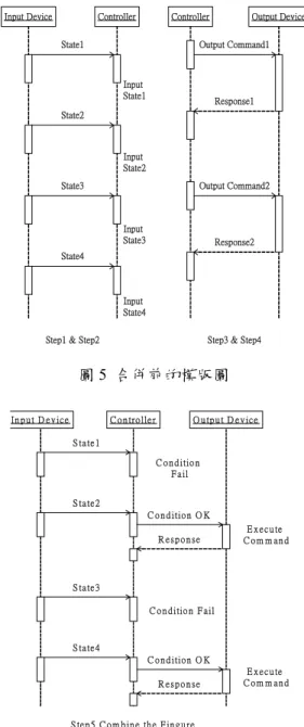
(3) 三、SpecTRM 的延伸. 接 著我們 依 SpecTRM-RL 的 模型畫 出 UML 的時序圖以便於視覺上即能了解子系統. 我們延伸的方法首先依 SpecTRM-RL 畫. 間的互動狀況。我們將時序圖分為輸入裝置與. 出 每 個 物 件 的 狀 態 轉 換 圖 ( state transition. 控制器間的互動(及送狀況/事件訊息) ,和控. diagram)和 UML 時序圖,再者在狀態圖及. 制器與輸出裝置間的互動(即輸出指令)。其. AND/OR 表 中 加 上 失 效 條 件 ( failure. 方法如圖 5,6 所示。. conditions ) 成 增 添 式 狀態 轉 換 圖 和增 添 式 SpecTRM-RL 模型,最後以有系統的方式合成. Input Device. Controller. Controller. State1. 故障樹,以進行安全分析。本研究的步驟如圖 3 所示。各步驟詳細於下面各節。. Output Device. Output Command1. Input State1. Response1. State2. Augmented SpecTRM-RL Model (+ Failures + Assertions) State Transition. Input State2. Global View. State3. Augmented State Transition Diagram. Output Command2. Sequence Diagram. (+ erroneous events reaching each state). Input State3. Systematic Fault Tree Synthesis. Response2. State4. (for Safety Analysis). 圖 3 我們的方法 Input State4. 3.1 根據 SpecTRM-RL 來建立狀態轉換圖及. Step1 & Step2. UML 時序圖. Step3 & Step4. 圖 5 合併前的模版圖 In p u t D e v ic e. 我們首先依 SpecTRM 的規格來畫其輸入. C o n tro lle r. O u tp u t D e v ic e. S ta te 1. 裝置、輸出裝置、及控制器的狀態轉換圖(state. C o n d itio n F a il. transition diagram) ,包含其間訊息的傳遞與接 S ta te 2. 收,如圖 4 所示。有的狀態間的順序無法完全. C o n d itio n O K. 推 測 出 , 得 加 上 主 觀 專 業 知 識 ( domain. R esponse. knowledge)來完成。. E x e c u te C om m and. S ta te 3 C o n d itio n F a il. Input Device. Output Device. S ta te 4 C o n d itio n O K State1. State1. State2. Input Device State1/ send(controller,State1). R esponse. Input Device State3/ send(controller,State3). State4. Input Device State4/ send(controller,State 4). Receive(controller,m)[m=Com mand2]/Perform action2. Receive(controller,m)[m=Com mand1]/Perform action1. S te p 5 C o m b in e th e F in g u r e. Input Device State2/ send(controller,State2). State3. E x e c u te C om m and. State2. 圖 6 合併後的完成圖. Controller Receive(Sensor,m)[m=State2]/ Send(Output Device,Command2). 3.2 建立增添式狀態轉換圖及增添式. Normal Receive(Sensor,m)[m=State4]/ Send(Output Device,Command1). SpecTRM-RL 模型. 圖 4 推導出的 SpecTRM-RL 通用狀態轉換圖. 為了利於後續故障樹的建立及分析,我們. 3.
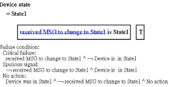
(4) 在狀態轉換圖上添加的失誤的原因(failure conditions)。我們有 2 個前提: 1. 我 們 是 針 對 被 電 腦 控 制 的 子 系 統 (Controlled subsystems)畫出其故障情況。 2.假設子系統每一狀態皆由單一個 (unique) 觸發訊息或事件決定。 我們的方法如下(如圖 7 所示):. 圖 8.. Augmented AND/OR 表 (加上 Failure). 1.(a)實線表示是正常情況的狀態轉換。虛線 表示錯誤的狀況。圖 7 中(a)表示正常. 3.3 系統化的建構故障樹. 狀況。 2.增加(b)該發生卻沒發生的狀況。子系統. 我們的方法與 Leveson 方法的主要差異在. 原先在 Q,當收到不是 P( ¬ P)的訊息—. 於我們主要發展了一套由 SpecTRM-RL 產生. 應該轉換到另一個狀態時,子系統卻停留. 故障樹的方法。雖然 Leveson 極力批評 event-. 在 Q。. chain 式安全分析方法[8],然而 event- chain 方. 3. 增 加 ( c ) 不 該 發 生 卻 發 生 的 狀 況 。 因. 法如故障樹等,仍是延用最多,最多人熟稔的. ¬ P ∧ Q 的虛線表示沒收到 P 的訊號子系. 系統安全分析方法,我們相信可與 SpecTRM. 統卻自動進入 Q 的錯誤狀況(c)。. 的方法合併,並不衝突。 電腦控制系統包含主動及被動式系統,主. (a). 動式的系統,不會受外在的訊息控制,例如: 火車。被控制的系統,接受外在的訊息控制,. P. 例如:柵欄。我們的故障樹建構方法如下: ﹁P^Q Q. 1.. (c). ¬P. Top Event 先確認危險情況的狀態所在位 置,先判斷是主動物件還是被動物件,主 動物件則從其時間點往回推上一個狀. (b). 態;而被動物件則根據增添式狀態轉換 圖,如圖 7 中可看出有 3 種錯誤的原因,. 圖 7 增添式狀態轉換圖. 該作沒做(Critical failure),不該做而做 (Spurious signal),和錯誤地維持現狀. 同樣地,我們可在 AND/OR 表中增加故. (No action),再進行步驟 2。. 障情況描述。Critical failure 指該發生卻沒發生 的錯誤情況,而 Spurious signal 指不該發生卻. 2. 針對下列錯誤推測前因: (a)訊息錯誤發生. 發 生 的 錯 誤 狀 況 , No Action 表 示 Output. 的原因,可以從時序圖判斷,傳送端和接. Device 在 Q 狀態並且當收到 Input Device 其他. 收端都有可能出錯,要視錯誤情況而定。. 狀態時,應該送出根據其他狀態的指令,但卻. (b)硬體和狀態轉換的錯誤,可以參考. 沒有動作。根據圖 7 我們畫出如圖 8 示意圖。. 我們增添式狀態轉換圖。 (c)軟體錯誤則 可以經由增添式 AND/OR 表中的錯誤情 況(Failure)來找原因。 3. 重複 1, 2 的步驟來建構故障樹。. 4.
(5) 柵欄、和控制軟體三部分。火車有 Traveling、. 我們所建構出的故障樹的模版(template) 如圖 9 所示。線段上的文字為說明或註明查何. Approach、Ingate 和 Exit 四個順序狀態接送訊. 種圖表。. 息通知 Controller,Controller 則送訊號控制 Gate 的上升及下降。 Undesired event (Contain erroneous State Q) Augmented State Transition Diagram. No Action remain the old State. Errorneous Action Spurious signal ﹁P^Q. ﹁P. Sequence diagram. MSG check. MSG OK. Hardware failure. MSG OK. Receiver failure. MSG OK. Receiver failure. Augmented State Transition Diagram. Software failure. 3. 4. MSG Failure. Trace P`s reason. Receiver failure. 圖 11 火車過平交道 SpecTRM-RL 系統圖. MSG error. Software failure. 5. 6. MSG error 7 Erroneously received P. Input MSG mistaken as p. MSG wasn`t received. Sequence diagram. Augmented AND/OR table. H.W. abnormal behavior. MSG Lost. 2 MSG wasn`t sent. MSG check. MSG Failure. Trace Q`s reason. Augmented AND/OR table. 1. Sequence diagram. MSG check. MSG Failure. Sender failure. P^Q. Train. Gate. 圖 9 系統化故障樹之合成(Synthesis). Raised. 其故障情境可由 UML 時序圖表達。如圖 10 所示。. Traveling. Train Traveling/ send(controller,Traveling). Approach. Train Approach/ send(controller,Approach). Ingate. Train Ingate/ send(controller,Ingate). Receive(controller,m)[m=Up]/ Raise the Gate d. Receive(controller,m)[m=Down]/ Lower the Gate. Lowered. Controller Receive(Sensor,m)[m=Approach]/ Send(Gate,Down). Exit. Train Exit/ send(controller,Exit). Normal. ﹁P : remain the old state. Controller. Device. Controller. Receive(Sensor,m)[m=Exit]/ Send(Gate,Up). Device. Controller. Device. 圖 12 火車過平交道狀態轉換圖 1.Hardware failure. 2.Software failure. 3.MSG lost. 圖 13 為相關的 AND/OR 表。我們根據此. Q : erroneous action. Controller. Device. Controller. Device. Controller. Device. Controller. 表畫出互動時序圖如圖 14。. Device. Receive wrong MSG. 4.Hardware abnormal behavior. 5.MSG error. 6.Software failure. 7.receive MSG error. 圖 10 時序圖表達故障情境. 四、應用案例 4.1 火車過平交道應用. 圖 13.. 控制柵欄指令之 AND/OR 表. 我們以單一火車通過平交道的應用案例. 接著我們根據 3.2 節的方式畫出增添. 來說明我們方法的可行性及有效性。其基本. 式態轉換圖(圖 15,16)及增添式 AND/OR 表(圖. SpecTRM-RL 模型如圖 11 所示,其推導出的. 17),兩者皆包含前述錯誤的狀況(failures)。. 狀態轉換圖如圖 12 所示。本系統包含火車、. 5.
(6) 在圖 18 中我們可以發現主要有 3 種類的 T ra in 1. C o n tro lle r. G a te. 錯誤:. T ra in S ta tu s T ra v e lin g. 1.硬體錯誤(Hardware failure): 編號包含 1,2, 9, 10, 11, 15 事件。 (例如其中編. T ra in S ta tu s A p p ro a c h G a te C o m m a n d L o w e r. 號 1 表示柵欄硬體故障). G a te S ta tu s L o w e re d. T ra in S ta tu s I n g a te. 2.軟體控制錯誤(Software controller failure): 編號包含 5,6,13。(例如其中編號 5 表示控制. T ra in S ta tu s E x it G a te C o m m a n d R a ise. 器判斷錯誤). G a te S ta tu s R a is e d. 3.訊息傳遞錯誤(MSG failure): 編號包含 3,4,7,8, 12,14, 16。(例如其中編號 3. S te p 5 C o m b in e th e F in g u re. 圖 14 火車過平交道的合併時序圖. 表示柵欄沒收到訊息的錯誤). Output Controller Command. Failure: Critical failure: Gate Status in Raised ^ Train1 in Approach ^ ﹁send ( Gate , Down ) Spurious signal: ﹁ ( Gate Status in Raised ^ Train1 in Approach) ^ send ( Gate , Down ). Failure: Critical failure: Gate Status in Lowered ^ Train1 in Exit ^ ﹁ send ( Gate , Up ) Spurious signal: ﹁ ( Gate Status in Lowered ^ Train1 in Exit) ^ send ( Gate , Up ). Gate Status. Raised’ Failure: Critical failure: Gate Status Signal is Raised ^ ﹁ Gate in Raised Spurious signal: ﹁ Gate Status Signal is Raised ^ Gate in Raised No Action: Gate State in Raised ^ ﹁ Gate Status Signal is Raised ^ No Action. 圖 15 增添式火車狀態轉換圖. Lowered’ Failure: Critical failure: Gate Status Signal is Lowered ^ ﹁ Gate in Lowered Spurious signal: ﹁ Gate Status Signal is Lowered ^ Gate in Lowered No Action: Gate State in Lowered ^ ﹁ Gate Status Signal is Lowerd ^ No Action. 圖 17 增添式 SpecTRM-RL 模型 接 著 我 們 以 意 外 事 件 ( top event ) (Gate=Raised) ∧ (Train=Ingate)為例,根. 假設我們有興趣的是軟體的故障原因編 號 5,軟體判斷錯誤未送出訊息,則其情境的. 據圖 9 方式產生故障樹如圖 18 示。. 時序圖如圖 19 示。. 經由此故障分析可分析出可能的不安全 處,可重新設計以增進安全。例如當我們發現 可 能發 生軟體 錯誤 時,可 加上 多元化 設 計 (N-diversity version)或硬體 interlock。而硬 體的錯誤時,可新增硬體結構的一些限制或多 元化設計(design diversity) ,以確保系統的安 全性。 圖 16 增添式柵欄狀態轉換圖. 6.
(7) (Gate=Raised) ^ (Train=Ingate). P: MSG=Up Q:Gate=Raised ﹁P^ Q. P^Q. ﹁P. Old Q`=Raised ^ ﹁MSG=Up ^ Q=Raised. Gate Augmented State Transition diagram. Train: Approach->Ingate. Receive (Controller,m)[m=Up]/ Let Gate Raise. Train: Approach->Ingate. ﹁ Receive (Controller,m)[m=Up]/ Let Gate Raise. Train: Approach->Ingate. Train Augmented State Transition diagram. Gate Augmented State Transition diagram. Train Augmented State Transition diagram. Gate Augmented State Transition diagram. Train Augmented State Transition diagram. MSG=Down. 1.Gate Failed. 2.Gate Lowered Delay. Gate Statechart. Sequence diagram. MSG failure. MSG OK. No MSG Controller send Down ^ ﹁ Gate receive. ﹁ Controller send Down ^ ﹁ Gate receive. Controller send Up ^ Gate receive Up. ﹁ Controller send Up ^ Gate receive Up. Sequence diagram. Sequence diagram. Sequence diagram. Sequence diagram. MSG OK. MSG failure. 11.Gate failure. 16.MSG Failure. Gate Statechart. Sequence diagram. Trace p`s reason MSG OK. MSG failure 3.Gate didn`t receive. 4.Gate receive very late. Sequence diagram. Sequence diagram. MSG failure MSG OK. Controller receive Approach ^ ﹁ Send Down. ﹁ Controller receive Approach ^ ﹁ Send Down. Controller receive Exit ^ Send Up. ﹁ Controller receive Exit ^ Send Up. Sequence diagram. Sequence diagram. Sequence diagram. Sequence diagram. 12.MSG Failure Sequence diagram. Trace p`s reason MSG failure. MSG OK. MSG failure. MSG OK 5.Controller failure. 6.Controller works delay. AND/OR Command Lower. Sequence diagram. Gate check failure. Train1 check failure. Gate AND/OR Lowered C.F.. Train1 AND/OR Approach C.F.. Sensor send Approach ^ ﹁ Controller receive. ﹁ Sensor send Approach ^ ﹁ Controller receive. Sensor send Exit ^ Controller receive. ﹁ Sensor send Exit ^ Controller receive. Sequence diagram. Sequence diagram. Sequence diagram. Sequence diagram. 7.Controller didn`t receive. 8.Controller receive very late. 9.Sensor delay. 10.Sensor failed. 15.Sensor automatic send Exit. Sequence diagram. Sequence diagram. Sequence diagram. Train Statechart. Train Statechart. 13.Controller automatic send Raise AND/OR Command Raised. 14.MSG failure. Gate check failed. Train1 check failed. Sequence diagram. Gate AND/OR Raised S.S.. Train1 AND/OR Exit S.S.. 圖 18 火車過平交道之故障樹. 斷言可表達變數之間的預期正常關係,在執行 Train. Controller. 時電腦可以檢查此類預期正常關係是否在。若. Gate. 不存在,應警示操作員。火車的例子較簡單,. Approach. Raised. 斷言的需求不很明顯。以另一常被引用的規格 案例蒸汽鍋爐(Steam Boiler)[2]而言,此案. Ingate. 例中有幫浦(pump),加熱器(heater),放水. Raised. 閘門(water valve) ,釋壓閘門(release valve) , 而系統中有些程序變數(Process Variable) ,例 如溫度、水位、壓力。我們建議可能的斷言可 分 為 裝 置 與 裝 置 之 間 ( Device-Device. 5.Controller Failed. relation ), 裝 置 與 程 序 變 數 之 間 (Device-Process variable relation),和程序變. 圖 19 軟體錯誤情況. 數和程序變數之間(Process variable-Process variable relation)等類型,以下為部分範例。. 4.2 限制(Constraints)外加斷言(Assertion). 1.. 裝置之間(Device - Device relations): 例如:水位太低開幫浦,並關放水閘門。. 除了上述靜態事前的故障樹安全分析法. 2. 裝置—程序變數之間(Device - Process. 外,SpecTRM-RL 的限制(constraints)提供. variable relations):. 執行時的檢查。SpecTRM-RL 所顯示的限制,. 例如:幫浦打開 → 水位上升. 多數為第一變數,裝置在時間範圍等上的限. 釋壓閘門打開 → 壓力下降. 制。我們以為尚不足以確保系統執行時的安全. 3. 程 序 變 數 — 程 序 變 數 之 間 ( Process. 性。,我們建議增加斷言(Assertion)[13]。. 7.
(8) developed by an object-based method improves requirements specification for safety-related systems, ” Reliability Engineering and System Safety, vol. 63, pp. 111-125, 1999.. variable – Process variable relation): 例如:目前鍋爐中的水量+幫浦加入的水 量—放水閘門的出水量=下一刻的鍋 爐中的水量 以上的斷言例子,多少都涉及時間上的動. [4]. D. Harel, “ Statecharts: a visual formalization for complex systems,”Sci. Comput. Program. Vol. 8 , pp. 231-274 , 1987.. [5]. P.E. Heimdahl and “Completeness and hierarchical Requirements, ” IEEE Software Engineering, June 1996.. [6]. Cliff B. Jones, Systematic Software Development Using VDM, Prentice Hall, January 1990.. [7]. N. G. Leveson, “Intent specification: an approach to building human-centered specifications, ” IEEE Transactions on Software Engineer, Vol. 26, No. 1, January 2000.. 作與結果的效應。斷言亦可有其他多種類型, 可見 [13]的分類。電腦可在執行時檢查系統是 否符合預先設定的斷言的關係及限制範圍數 值,若不符合,則執行預設的處理方式 (Exception handling)或警示操作員。執行此 檢查斷言及限制的電腦可以與控制部分 (controller)是相同的,亦可以是獨立的另一 個斷言處理器(assertion processor) 。如此執行 時限制加上斷言的檢查可彌補事前安全分析 的可能不足之處。. 五、結論. [8] N. G. Leveson, “A new accident model for engineering safer systems,” Proc. of International System Safety Society Conference, August 2002.. 本研究延伸了 Leveson 的 SpecTRM-RL, 增加了狀態轉換圖和時序圖,並在轉換圖及 AND/OR 表加了錯誤到達此狀態的可能轉換. [9]. 條,我們並發展了有系統的建構故障樹的方 法。我們的圖形方式(如 Sequence diagrams, augmented state transition diagrams) 增 進. [10]. SpecTRM-RL 的可讀性,並可進行安全驗證, 以期提昇系統的安全性。未來擬將發展出的方. 評估具體的功效。. [1] J. R. Abrial,“The specification language Z : syntax and semantics,”Programming Research Group, Oxford, April 1980.. [3]. M. Cepin and B. Mavko, “ Fault tree. N. Rescher and A. Urquhart, Temporal Logic, Springer-Verlag, Library of Exact Philosophy, 1971.. [12]. Software Engineering Corporation, “SpecTRM User Manual,” 2001.. [13]. Swu Yih, Jeff Tian, “ Developing and checking prescriptive specifications for safety improvement,” Microprocessors and Microsystems, vol. 21, pp. 587-594, 1998.. 六、參考文獻. J. R. Abrial, et al., Formal Methods for Industrial Applications, Specifying and Programming the Steam Boiler Control, LNCS 1156, Springer-Verlag, Oct. 1996.. J.L. Peterson, Petri Net Theory and the Modeling of Systems, Prentice Hall, 1981.. [11] D. S. Rosenblum,“Towards a Method of Programming with Assertions, ” ACM Proceedings of the 14th international conference on Software engineering, June 1992.. 法及步驟加以自動化並應用於實際案例上以. [2]. N. G. Levson, consistency in State-Based Transactions on Vol. 22, No. 6,. 8.
(9)
數據
![圖 1 SpecTRM [12]](https://thumb-ap.123doks.com/thumbv2/9libinfo/8920817.263165/2.892.461.757.107.634/圖-spectrm.webp)
相關文件
FPGA –現場可規劃邏輯陣列 (field- programmable
FPGA –現場可規劃邏輯陣列 (field- programmable
FPGA –現場可規劃邏輯陣列 (field- programmable gate
FPGA –現場可規劃邏輯陣列 (field- programmable
FPGA –現場可規劃邏輯陣列 (field- programmable
As schools were provided with additional resources under different modes, some schools (e.g. those adopting IRTP) were not required to report to the Education Bureau (EDB)
In these lessons, students will evaluate the impacts of genetic engineering on our daily life, and analyze the moral issues raised in its development, especially those related
The second question in this paper is raised from the first question – the relationship between constructing Fo Guang Pure Land and the perspective of management beginning
