i
國
立
交
通
大
學
資訊學院 資訊學程
碩
士
論
文
一個路徑狀態偵測之傳輸控制協定-RSA TCP
A Route State Aware Transport Control Protocol
研 究 生:何文慶
指導教授:陳耀宗 教授
ii
一個路徑狀態偵測之傳輸控制協定- RSA TCP
A Route State Aware Transport Control Protocol
研 究 生:何文慶 Student:Wen-Ching Ho
指導教授:陳耀宗 Advisor:Yaw-Chung Chen
國 立 交 通 大 學
資訊學院 資訊學程
碩 士 論 文
A ThesisSubmitted to College of Computer Science National Chiao Tung University in partial Fulfillment of the Requirements
for the Degree of Master
in
Computer Science June 2011
Hsinchu, Taiwan, Republic of China
i
一個路徑狀態偵測之傳輸控制協定- RSA TCP
學生:何文慶 指導教授:陳耀宗 博士
國 立 交 通 大 學
資 訊 學 院 資 訊 學 程 碩 士 班
摘
要
當今許多通訊產品對於多媒體資料的需求越來越高,也同時擁有多種
網路介面方便使用者隨時隨地存取網路上的影音資料。本論文研製一套通
訊協定,可方便擁有多個網路傳輸介面之產品使用。上層的應用程式以及
底層的實體層都不需要做出修改,本通訊協定可以主動偵測資料傳輸路徑
的狀態,來決定該如何動態轉移資料傳遞路徑,提升資料傳輸的可靠度與
流通量。
在這篇論文中,RSA TCP 著重在路徑選擇的控制。因為TCP本身擁有流
量控制的功能,所以路徑上如果發生錯誤或者壅塞,將會嚴重的影響TCP傳
輸的效能。RSA TCP的目標就是判斷出現有的路徑是否出現錯誤情況,並且
自動將原有的TCP資料流導引到另外的路徑上。
RSA TCP 能夠讓錯誤路徑上的資料封包轉移到其他正常的路徑上,如
果要求上層的應用程式來達成這樣的效果,那麼每一個有使用網路功能或
者跟網路有關連的應用程式都得修改,加上產品的平台種類繁多,作業系
統除了種類多、版本也多,如果要應用程式達成這樣效果,將會是一筆非
常可觀的花費。如果要求底層的網路層來做到路徑偵測,網路層本身只有
IP相關的資訊,除了IP以外,網路層沒有其他任何的資訊可以判讀路徑的
ii
狀態,所以網路層是不可能達成這樣的效果。
RSA TCP 本身跟上層的應用程式是互相獨立的,跟底層的網路層或者
實體層也互不干涉,也就是說,使用RSA TCP 來達成路徑偵測並轉移,是
最方便也是最符合經濟效益的一種方法。我們也在NS2的模擬器上跟原有的
方法比較效能。實驗顯示,與傳統TCP相比,RSA TCP可以達到大於26%的流
通量。
iii
A Route State Aware Transport Control Protocol – RSA TCP
Student: Wen-Ching Ho Advisor: Dr. Yaw-Chung Chen
Degree Program of Computer Science
National Chiao Tung University
Abstract
There are more and more communication devices or portable devices equipped with multiple interfaces for users to request much higher multimedia data than before. Users could access multimedia data anywhere and anytime. The protocol studied in this thesis can be adapted by the devices with multiple interfaces to access the internet without requiring the modifications of the applications in the upper layer. There is also no need for lower physical layer to do any modifications. The protocol can detect the state of the routing path automatically to determine how to transmit data through the new path dynamically so as to improve the reliability and throughput.
RSA TCP emphasizes on the path switching control for TCP packets. TCP protocols feature flow control, its performance may be affected by the congestion or error along the path. RSA TCP focuses on how to determine whether the paths encounter a problem or not. After the decision made is to switch routing path, the routing information will be updated to re-direct the data stream to the new next hop.
TCP packets can escape from the congestion path automatically. If users request applications to do the same job, every network associated applications need to be modified. And there are various platforms and operation systems. The modification requested on application will cost a lot. It is infeasible for users to request the change in network layer, because network layer only contains IP information and is no routing information maintained in this layer, therefore it is unable know what happened and what to do. RSA TCP is independent of upper application layer and network layer, and it helps system keep the best performance for data communications with low cost.
iv
We perform the experiment for our method on NS-2 simulator and compare the performance with the original designed method. It shows that, comparing with traditional TCP, more than 26% throughput improvement can be achieved with RSA TCP.
v
Table of Contents
Degree Program of Computer Science...iii Abstract ...iii Table of Contents ...v List of Figures ...vii List of Tables...ix 1. Introduction... 1 2. Background... 7 2.1 Review of TCP... 7 2.1.1 TCP Tahoe... 8 2.1.2 TCP Reno ... 9 2.1.3 TCP New Reno ... 9 2.1.4 TCP SACK (TCP with Selective Acknowledgements)... 9 2.1.5 TCP Vegas ... 10 2.2 Congestion Control Mechanism of TCP... 11 2.2.1 Slow Start ... 12 2.2.2 Congestion avoidance ... 13 2.2.3 Fast Retransmission ... 13 2.2.4 Fast Recovery ... 14 2.2.5 Timeout ... 15 2.3 Problems on TCP ... 16 2.3.1 Packet Loss ... 17 2.3.2 Long Queuing delay... 18 2.3.3 Different Routes ... 18 3. Proposed Method ... 19 3.1 Base TCP Edition of Proposed Scheme... 19 3.2 Purpose of Proposed Scheme ... 21 3.3 Proposed Scheme... 22 3.3.1 RSA Trigger Criteria ... 22 Duplicate ACK ...23 Timeout...24vi 3.3.2 How Polling Period Determined... 25 3.3.3 How RSA TCP works ... 28 4. Simulation Results ... 33 4.1 Scenario I ... 34 4.1.1 Network topology ... 34 4.1.2 Simulation Steps... 36 4.1.3 Simulation results – Scenario I + Full Speed TCP Vegas ... 37 4.1.4 Simulation results – Scenario I + Blocked TCP Vegas ... 39 4.1.5 Simulation results – Scenario I + RSA TCP ... 40 4.2 Scenario II ... 43 4.2.1 Network topology ... 43 4.2.2 Simulation Steps... 45 4.2.3 Simulation results – Scenario II + Full Speed TCP Vegas ... 46 4.2.4 Simulation results – Scenario II + Blocked TCP Vegas ... 47 4.2.5 Simulation results – Scenario II + RSA TCP ... 48 4.3 Scenario III... 50 4.3.1 Network topology ... 50 4.3.2 Simulation Steps... 52 4.3.3 Simulation results – Scenario III + Full Speed TCP Vegas ... 53 4.3.4 Simulation results – Scenario III + Static TCP Vegas... 54 4.3.5 Simulation results – Scenario III + RSA TCP ... 54 4.4 Scenario IV... 55 4.4.1 Network topology ... 55 4.4.2 Simulation Steps... 56 4.4.3 Simulation results – Scenario IV + Full Speed TCP Vegas ... 57 4.4.4 Simulation results – Scenario IV + Static TCP Vegas... 58 4.4.5 Simulation results – Scenario IV + RSA TCP... 59 4.5 Mathematic analysis ... 60 4.5.1 Staying Period... 60 4.5.2 Performance Improvement... 62 4.5.3 Roaming Effect ... 62 5. Conclusion and Future Works ... 63 Reference ... 66
vii
List of Figures
Figure 1 Sample network architecture in real environment... 1 Figure 2 Application independent packet flow ... 4 Figure 3 Progressive flow of TCP editions ... 7 Figure 4 The phases of Slow‐Start and Congestion Avoidance. ... 13 Figure 5 Phases of Fast Retransmission ... 14 Figure 6 The phase of Fast Retransmission and Fast Recovery ... 15 Figure 7 RSA TCP Work Flow ... 23 Figure 8 Diagram for Duplicate ACKs ... 24 Figure 9 Timeout Detection Timing... 28 Figure 10 RSA TCP State Machine ... 30 Figure 11 Flow diagram of connection failure but no more new paths... 32 Figure 12 Format of TCP Header ... 32 Figure 13 Network topology of simulation I ... 35 Figure 14 Scenario I: The simulation result of throughput in Full Speed mode... 38 Figure 15 Scenario I: The cwnd in Full Speed mode... 38 Figure 16 Scenario I: The simulation result of throughput in Blocked TCP... 40 Figure 17 Scenario I: The cwnd in Blocked TCP... 40 Figure 18 Scenario I: The simulation result of throughput in our proposed method – RSA TCP... 42 Figure 19 Scenario I: The cwnd in our proposed method – RSA TCP mode... 43 Figure 20 Scenario I: The throughput comparison of the three approaches... 43 Figure 21 Scenario II: The Simulation result of throughput in Full Speed mode ... 46 Figure 22 Scenario II: The cwnd in Full Speed mode... 47 Figure 23 Scenario II: The simulation result of throughput in Blocked TCP mode ... 47 Figure 24 Scenario II: The cwnd simulation result in Blocked TCP mode ... 48 Figure 25 Scenario II: The simulation result of throughput in RSA TCP mode... 48 Figure 26 Scenario II: The cwnd in out proposed method ‐ RSA TCP mode ... 49 Figure 27 Scenario II: The throughput comparison of the three approaches... 49 Figure 28 Network topology of Scenario III & Scenario IV ... 51 Figure 29 Scenario III: The simulation result of throughput in Full Speed mode... 53 Figure 30 Scenario III: The simulation result of throughput in Congested TCP ... 54viii
Figure 31 Scenario III: The simulation result of throughput in our proposed method – RSA TCP... 55
Figure 32 Scenario IV: The simulation result of throughput in Full Speed mode ... 58
Figure 33 Scenario IV: The simulation result of throughput in Congested TCP ... 59
ix
List of Tables
Table 4.1 Parameters of simulation for Scenario I... 35 Table 4.2 The result of three approaches with beta = 3 ... 43 Table 4.3 Parameters of simulation for Scenario II... 44 Table 4.4 The result of three approaches with beta = 30 ... 50 Table 4.5 Parameters of simulation for Scenario III... 51 Table 4.6 Throughput List of Scenario III... 55 Table 4.7 Throughput List of Scenario IV ... 601
1. Introduction
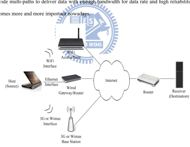
In recent years, there is an explosive growth of the multimedia related applications running on various devices, especially smart phones, mobile phones and tablet PCs. The applications may acquire different kinds of information and multimedia data from the Internet. People can use the portable devices to watch to the network news, such as ABC or NBC news. They also can browse the movies or clips from a video on demand (VoD) system. The applications existed on everything you can think. Popular community websites have text articles, text message, audio files and video clips embedded. How to maintain a host that provide multi-paths to deliver data with enough bandwidth for data rate and high reliabilities becomes more and more important nowadays.
Figure 1 Sample network architecture in real environment
2
There are different kinds of network interfaces for devices to access the Internet, these include Ethernet, 3G, wireless 802.11 WiFi, blue tooth, and 802.16 WiMAX, etc. Multiple paths may be coexisting for data transport at the same time. But a device is usually configured with only one of them as default routing path, which might be the best path for the user. The default path selected by the user may have the best performance, or the largest bandwidth, or the widest coverage depending on the user’s preference. The remaining interfaces are prepared to backup the default connection. No matter what interface is in active, the other interfaces may not be able to transmit the data at the same time so as to increase the outgoing bandwidth. Also, the backup paths might not be activated to replace the current path that might have lost the connection to the destination or been congested. Usually the devices are not aware of the problem occurred on the running path even though the other backup paths are ready or idle. The backup mechanism does not activate automatically to recover the failure of the current path.
There is a way to detect the path failure. In some implementation, the path switching might be determined by the applications located in the higher layer. Some applications have timeout mechanism to inform users that current path has errors. After users receive the information, they can switch to the alternative path manually. For this case, users may need to spend a lot of time in manual operation and waiting. On the other hand, if there is no timeout mechanism, users may have to wait for a very long time until they decide to drop the current connection and switch the interface. Both above situation are wasting time and inconvenient to users. No matter what kinds of applications are embedded in user’s device, the user will feel unsatisfactory for the idle period of the multimedia data when the current connection gets down or congested.
As the applications need to recover the path problem, they have to deal with the selection of path and request network layer or transport layer to report the status of the running path.
3
This kind of process may take too much system resources including both CPU time and memories. Generally, the mobile device is not as powerful as desktops. The above kind of path recover operation might slow down other applications which are also running on the device. In case of path failure, from the moment a condition occurred on the connection to the time the condition been fixed is quiet long, it usually takes seconds.
Transport layer is much closer to the network status than application layer. If the transport layer can detect the status of the network and determine the best timing to change the route path and where to go, this might make the path switching be independent of all upper layers. It is not necessary for the upper layer to spend time on polling the status of the network, so that the CPU time can be saved to speed up other processes. And the network status information is also not necessary to be preserved in the memory of the end device.
TCP and UDP are the most popular protocols to carry the standard-based multimedia data over the Internet. UDP will be chosen first instead of TCP for real-time multimedia data because it can deliver the data with desired data rate. In an ideal environment without congestion, UDP sender can send data to receiver with the data rate in the receiver side being close to that in the sending rate. If the data rate is too high for buffer to handle, the data packets will be dropped. If the data rate is too slow, the quality of multimedia playback will be poor or it may causes the video clip to be stuck. But UDP still has some disadvantages. It is not a congestion aware protocol. Even the network is congested with heavy traffic, UDP does not reduce its data rate. Therefore, UDP potentially results in a congestion collapse and it is unable to construct a fair network.
Now more and more applications use TCP to send data even TCP has two obvious disadvantages, congestion control and fluctuation data rate [13]. With TCP protocols, the path errors will eventually lead TCP host side to back off the size of congestion windows (cwnd). This slows down the data sending rate in the host. When an abnormality occurs, the TCP
4
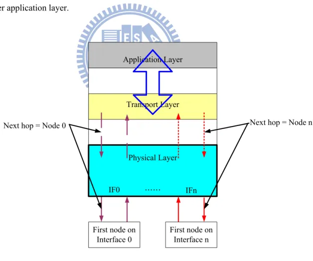
protocol will use its original mechanisms, fast retransmission or fast recovery to eliminate the abnormality. If the mechanisms are not working well, TCP has to handle the possible situation – packet loss or timeout. Both phenomena force TCP to enter congestion handling phase and the data rate decreases. So we need an active transport protocol to handle this situation. Not only passively stop the packets from being sent to the congested path, but also switch the entire path to an alternative one to retain the original sending rate. As Figure 2 illustrated, the requests and responses are handled by the transport layer, which can easily assign the outgoing packets with different interface. To the application layer, the changes in the lower layer will be transparent. Our proposed method - RSA TCP is able to detect the abnormality and send the data packets to another existed interface without having to inform the upper application layer.
Application Layer
Transport Layer
Physical Layer
IF0 …… IFn
Next hop = Node 0 Next hop = Node n
First node on Interface n First node on
Interface 0
5
First, RSA TCP will not enter the back off process immediately as the abnormality occurs along the path. Instead, RSA TCP will search a backup path to replace the abnormal path and try to maintain the performance same as that in original stable state. Second, packets are transmitted to another path. If the new path is healthy, it will become the new backup outgoing routing path during the waiting period for the elimination of abnormality occurred on the default path. Third, the main default route is usually the most efficient path for the sending source. Even the RSA TCP is switching the data to the new path, it still tries to switch the ongoing data transmission back to the original path if the problem in the original path is cleared.
If the abnormality happened on the link directly attached to the host, the host will drop out the physical link and the routing information will also be updated. Host will not transfer the packets to the abnormal link any more. If the abnormality happened on the link behind the physical link between host and gateway, so called last mile, host will not update the routing table, because the physical link is still alive and the physical layer will not trigger any lost link events to inform upper layer. This is a kind of starvation of data. RSA TCP can detect the status of the path and make the decision regarding path switching. If it decides to switch path, RSA TCP will select a path among the available outgoing paths.
In homogeneous network, there will be some interesting conditions. Is it possible that the alternative path is even worse than the original one? Yes. The reason forced RSA TCP to drop out current routing path is packet timeout. This means the current path is not healthy enough to carry the desired data rate. The path switching is necessary. If the new path is still congested or heavy loaded, the path switching will be performed again. If there is no more path to switch to, RSA TCP will stay on the last selected path and still periodically listen to the status of initial path. What is improved by RSA TCP in this situation? Not at all. There is no any good path to go. RSA TCP’s objective is dropping out the poor one and switching to
6
another one, but RSA TCP cannot guarantee the quality of the new path. The information of the path can only be obtained after the data packets are transferred to the destination. RSA TCP will use the RTT of packets to detect the status of the new path over again.
The description mentioned above is mostly talking about the homogeneous network, in which most nodes along the path are traversed commonly. Even the source router is changed by RSA TCP, the rest of the path to the destination might be the same and it is quite possible that the abnormality still stay on the path. RSA TCP would be more suitable to run on the host which connects to two or even more heterogeneous networks.
For heterogeneous networks, taking 3G network for example, the node has a base station to help the node to register to the 3G ISP and transfer the data to the destination. After base station receives the data sent by the source node, the data packet will be delivered through the ISP private network. The data packet transferred in telecommunication network is relatively stable. Eventually the data packets will enter the backbone network through the ISP private main trunk. Before entering the backbone, there is no way for the data packets going through the nodes same as that in homogeneous network. There will be very few common nodes traversed in heterogeneous network from source to the destination. That means, it is very likely that the data packets transferred on the new path can escape from the congested paths and reach the destination.
The rest of the thesis is organized as follows. In Chapter 2, the background of TCP is presented. In Chapter 3, the purpose, architecture and mechanism of proposed protocol is discussed. In Chapter 4, experiments are performed and results are illustrated and compared. Future work and conclusion are both addressed in Chapter 5.
7
2. Background
More and more applications use TCP protocol to guarantee the completeness of transferring multimedia files, such as video clips. The files need not only the integrity but also the short delivery time. People might use various kinds of devices, such as smart phone, plate computer, mobile phone, and GPS, to browse the resource on the Internet. In the past, UDP was considered first in transferring the files or media data on the Internet to meet the real time requirement. Considering the completeness of the transferred files, TCP protocol becomes more and more popular as the protocol for carrying the end to end data transport.
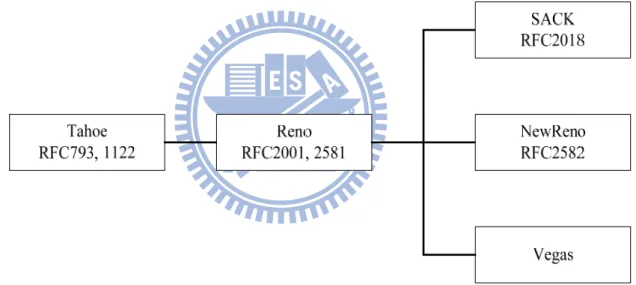
Figure 3 Progressive flow of TCP editions
2.1 Review of TCP
The basic TCP standard [1] described in RFC 793 defined the window-based flow control and a timeout timer. The congestion avoidance scheme was first added in TCP Tahoe[2]. In TCP Reno [4][5] the fast retransmission and fast recovery scheme was developed to enhance the congestion control mechanism. TCP Reno is a very popular version that is included in the operating system of most hosts and devices.
8
TCP New Reno modified the fast retransmission and added fast recovery mechanism. This causes TCP sending rate not to decrease too much. TCP SACK focused on the problem of retransmission for multiple consecutive packet losses. TCP Vegas uses RTT to detect the status of the network. TCP Vegas defines two variables, α and β, to be the lower bound and upper bound of rate variation, respectively. What expected is the difference between actual rate and the expected rate being between α and β. If the variation is smaller than α, the network traffic is light and source will increase the rate. Otherwise, if the variation is larger than β, the traffic on the network is too heavy, and TCP Vegas should decrease the data rate.
The transmission rate of TCP is depending on the cwnd (congestion window) in TCP sender side. Cwnd is the maximum size of unacknowledged packets that the sender can send to the network. When TCP receiver receives a packet, it should respond an Acknowledgment packet back to the sender with an SN (sequence number) to inform the sender that the packets with sequence number smaller than SN is already received by the receiver. After the sender receives an ACK, it increases the cwnd size and slides the cwnd toward the packets with unacknowledged serial number. The sending rate of TCP is as follows:
2.1.1 TCP Tahoe
TCP Tahoe is an early version at the starting period of TCP. TCP Tahoe has the basic structure of TCP, including Slow-start, congestion avoidance and recovery of the lost packets. TCP Tahoe also adds the Fast retransmission mechanism. Fast retransmission uses duplicate ACK as the stands. As long as there are three duplicate ACKs received, the sender retransmits the lost packet without waiting for the packet timeout. Triple duplicate ACKs are treated as timeout. TCP Tahoe will then reduce congestion window size to 1 and reset to slow-start
9
phase (refer to Section 2.2.1).
2.1.2 TCP Reno
Currently TCP Reno is the most popular and widely used TCP version. TCP Reno modified the algorithm in TCP Tahoe and added a Fast Recovery mechanism. TCP Reno enters fast recovery phase (refer to Section 2.2.2) instead of entering slow-start phase after retransmitting the lost packet.
2.1.3 TCP New Reno
TCP New Reno is derived from TCP Reno. TCP New Reno mainly modified the algorithm of fast recovery in TCP Reno. As TCP New Reno gets partial ACKs, TCP New Reno will not terminate the fast recovery phase. New Reno sender will keep retransmitting the packets with sequence number bigger than that in duplicate ACK until all lost packets are re-sent and acknowledged. After all lost packets were sent and acknowledged, TCP New Reno terminated the fast recovery phase. This helps TCP New Reno do not need to wait for timeout to retransmit the lost data as a large number of data packets got lost. TCP New Reno will retransmit a recovery packet every RTT at the fast recovery phase. If allowed, TCP sender can keep sending out the packets to increase the utilization of the link.
2.1.4 TCP SACK (TCP with Selective Acknowledgements)
The main purpose for TCP SACK[8] is to improve the TCP multiple packet loss problem. Traditionally, the TCP can only recover a packet loss within a RTT period. TCP SACK allows TCP sender to recover multiple packets within a RTT period. SACK receiver side can tell the sender which packets were received by using TCP option field to carry some extra information. There will be a block to record the consecutive segments that had been received
10
by the receiver side. The sender will retransmit the lost packet according to the information in the block. In [7], if there are multiple consecutive acknowledgment packets lost in the network, there is no way to inform the sender which packets are received by the receiver. What sender can do is only waiting for the packets to be timeout.
2.1.5 TCP Vegas
L. S. Brakmo and Peterson proposed a new congestion control scheme, TCP Vegas [9, 10, 11] in 1995. They think RTT can reflect the real situation that the network faces. So TCP takes the RTT into evaluation to know the traffic loading of the network being congested or light. According to the RTT value, TCP Vegas determines how to control the size of cwnd size. TCP Vegas can detect the variation of RTT to know the utilization of the network to avoid facing the periodical packet loss like TCP Reno [2][3]. The cwnd value for TCP Vegas is changing according to the network utilization or bandwidth, not periodical cycle. So TCP Vegas can run at a more stable rate. Comparing with other editions of TCP, TCP Vegas is more stable and fairer. If TCP Vegas finds the RTT diff is larger than β, TCP Vegas believes that the network is congested and decrease the cwnd size to reduce the traffic injected to the network. If the RTT diff is smaller than α in TCP Vegas, the remaining bandwidth on the network is still less than the expected bandwidth, and the cwnd size can be increased again. If the variance is kept in the range between α and β, the cwnd size will be kept without change. TCP Vegas detects the network bandwidth with the variation of RTT, not packet loss. Therefore, TCP Vegas can decrease the data rate before timeout taking place. If TCP can avoid entering timeout phase, the total performance can be increased up to 19%[11]. This helps TCP Vegas to run at a specific data rate that is closest to the best performance.
11
TCP Vegas cannot be adopted widely because TCP Vegas is relatively weak to compete with other transport protocols for the network bandwidth, especially compete with high aggressive protocols such as TCP New Reno. This will cause the network resource distribution to be unfair and the performance poor.
TCP Vegas also modified the mechanism of slow-start. It tries to use the bandwidth efficiently and avoid sending the packets too fast and cause the packet loss. TCP Vegas slows down the speed that cwnd increases at slow-start. At slow-start phase, cwnd takes 2 RTTs to double cwnd size. TCP Vegas also adjusts the value for ssthresh according to the difference between expected transmitting rate and actual transmitting rate. When TCP Vegas detects that there are waiting queues, it leaves the slow-start phase and enters the congestion avoidance phase.
2.2 Congestion Control Mechanism of TCP
Generally speaking, there are five ways for TCP to perform congestion control. They are Slow-Start, Congestion-Avoidance, Fast Retransmission, Fast Recovery, and Timeout Retransmission. TCP uses acknowledgement (ACK) to detect the status of the network and provides the reliable transport service. To tune the rate in the sender side, there is a variable,
(2)
12
ssthresh (Slow-start threshold) to separate the two states, Slow-start and
Congestion-avoidance.
2.2.1 Slow Start
Slow-start is the first state that TCP operation begins. The cwnd size is initialized to 1. This means in the beginning TCP can only send out one packet to the destination. When the sender gets an Acknowledgment packet from receiver, the cwnd size will be updated by comparing with ssthresh and configuring cwnd size according to Equation (4).
At slow-start phase, the cwnd size is increasing exponentially by 2 times. So slow-start is also called exponential growth phase. Slow-start phase ends at the point that the predefined threshold is reached. Then TCP will enter the Congestion Avoidance phase at next RTT.
Slow-start is named with a “slow”, but the growth of slow-start is very aggressive to go up to the threshold within a short time.
13
Slow Start and Congestion Avoidance
0 5 10 15 20 25 0 1 2 3 4 5 6 7 8 9 Time (RTT) Cw nd Figure 4 The phases of Slow‐Start and Congestion Avoidance.
2.2.2 Congestion avoidance
When the cwnd value is larger than ssthresh, the TCP enters the congestion avoidance phase. During this phase, when the sender gets an Acknowledgment packet from the receiver, the cwnd size will be increased by 1 [4]. This can slow down the speed that cwnd increases. As the cwnd is kept increasing, it will eventually reach the limit of the available network bandwidth in the long run, and packet loss will take place as the cwnd exceed a value that causes the sending rate larger than the available bandwidth.
2.2.3 Fast Retransmission
Packets traveling on the Internet might get lost due to congestion and connection down. The sequence number received might be out of order due to different paths existing on the network at the same time. These conditions may cause the receiver to send the acknowledgment packet with duplicate sequence number. After TCP receives three duplicate
14
acknowledgment packets, TCP will send the packets with sequence number larger than the sequence number carried in the duplicate acknowledgment packets. TCP keeps sending out the packet until timeout. And then TCP will reduce ssthresh to half of cwnd and reset cwnd to one. Fast Retransmission 0 5 10 15 20 25 1 2 3 4 5 6 7 8 9 10 11 12 13 14 15 16 Time (RTT) Cw nd Figure 5 Phases of Fast Retransmission
2.2.4 Fast Recovery
After TCP fast retransmission, the cwnd is reset to a half of cwnd. After that, receiving every acknowledgment packet means the receiver got one more packet, even the acknowledgment packet is a duplicate ACK. The cwnd can be increased by 1 whenever receiving an ACK.
15
Fast Retransmission and Fast Recovery
0 5 10 15 20 25 1 2 3 4 5 6 7 8 9 10 11 12 13 Time (RTT) Cw nd Figure 6 The phase of Fast Retransmission and Fast Recovery
2.2.5 Timeout
How to optimize the retransmission time out (RTO) value is very important. A small RTO value leads to unnecessary packet retransmission. On the other hand, a large RTO value results in the high latency of packet loss detection. In general, the RTO values should consider the current network Round Trip Time (RTT), which is the time required for a data bit traveled from the source to destination and come back to the source. Due to network traffic changes over time, RTT of one packet may be different from that of another. In TCP protocol, we have
smoothed (i.e. average) RTT ( ) and RTT variance ( ) to compute the RTO value.
Instantaneous smoothed RTT, RTT variance, and RTO are computed as the following
equations. Let t(k) be the Kth RTT value collected upon receiving acknowledgement packet.
And, let , , and RTO (k) be the values of , , and RTO respectively, when Kth
16
Where ub and lb are fixed upper bound value and lower bound value of RTO value. The range of constant α is, 0 < α < 1. And the range of β is 0 < β < 1. In general, α is set to 7/8 and β is set to 3/4. The variable γ is a binary exponential backoff (BEB) factor. It is initialized to 1, and doubled for every timeout event. And the value is set to 1 when a new ACK packet arrives.
2.3 Problems on TCP
The well-known advantage of TCP protocol is that TCP can guarantee the integrity of the transmitted files. Anything might take place on every network path. TCP concerns about the status of the connection. Delivering packets on paths with abnormality makes the performance to degrade.
The event that TCP most concerned is packet loss. When packets got lost, TCP assumes that there might be congestion in the network. It then tries to prevent the network traffic from becoming worse so it slows down the data sending rate with various kinds of mechanisms. In general, packet loss affects TCP performance a lot.
TCP detects the network abnormality status on the connection in advance. The long propagation delay might mislead TCP protocols to assume that the packet was lost. The propagation delay is a part of RTT which is also a reference of timeout. The long propagation delay affects the value of timeout.
On the Internet, there are may be multiple routing paths for a connection and the routing information is always changing. A file may be divided into pieces and carried by TCP packets.
(5) (6) (7)
17
The packets might be traveling with different path depending on the changing routing information that is kept in intermediate-routers. Packets traversing different paths may arrive at the destination out of orders. The order of incoming packets on the receiver and the order of incoming acknowledgements might be out of order. TCP takes the packet with missing serial number as being lost and then starts to retransmit the lost packets to the destination. This kind of retransmission will hold the size of cwnd or decrease the cwnd and consume the bandwidth.
2.3.1 Packet Loss
All packets injected to the router race the limited bandwidth to be transmitted to the link. No matter what kind of queuing policy adopted, there are always packets dropped in the router node. The reasons might be that the node is not powerful enough to process numerous packets, the incoming or outgoing link might have bad signaling or interference, or the outgoing bandwidth is not sufficient. Also, this might be caused by link failure.
When TCP protocol encounters the packet loss, it has to decrease the cwnd size to slow down the traffic injecting to the network. Every TCP protocol has its own algorithm to determine what to do. Fast retransmission and fast recovery will be applied to retrieve the few lost packets. Fast retransmission determines how much to eliminate and fast recovery determines how to retrieve the state as it is. Anyway, the data rate of TCP decreases. Even TCP SACK can recover multiple packets loss but the cwnd is temporarily frozen. The recovery period costs some packets to be re-sent. From total throughput concern, it is still lower than expected.
If the packet is timeout, TCP protocol has to enter slow start phase to reduce cwnd size to as small as possible. To release the loading from the path, TCP protocols did its best to re-start the transmission from one packet and allow the path become healthy later. For heterogeneous environment, the paths are coexisting independently.
18
2.3.2 Long Queuing delay
The TCP throughput is affected by RTT [1] a lot. If the end-to-end path to deliver the TCP packets features long queuing delay, TCP performance will be poor. Theoretically, the intermediate-nodes will have the best routing information for specific destination. But this kind of routing is not fair. All traffic will go through the selected path and there may be no traffic on the other paths which has smaller bandwidth. If the traffic is too concentrated, the queuing delay of the node would be long. Unfortunately, current routing policy does not implement the load balance mechanism among the connected paths. Traffic crowded in certain specific routing path is very common. The RTT of TCP packets is generally long in the real Internet and the performance is degraded due to the long RTT.
2.3.3 Different Routes
On the Internet, the intermediate-routers are linking to each other to construct a physical network. There are numerous paths linking a source and a destination. There are also various kinds of static routing configuration and dynamic routing protocol, such as OSPF, RIP, running among the routers to exchange the routing information. That means the route from source to destination for this packet might be different with other packets. Some nodes may be visit commonly by most packets in a connection, but some nodes may be only visited by few packets in the same connection. Among different paths, propagation delays are also different. The status of the paths is also concerned. A path might be congested and the packets going through the path is likely to be dropped. Another path might be selected temporarily due to its narrow bandwidth that enlarges the round trip time. There might also be a path that has poor linking signals due to miscellaneous reasons, such as a path whose outgoing path is disconnected or down.
19
All situations lead the TCP packets to a result – sequence numbers are not consecutive. No matter the sequence order received by receiver or the order of acknowledgment packets received by the sender, the transmission goes abnormal.
As we mentioned above, sequence numbers being not consecutive will make the sender to guess what happened to the path. And the TCP sender would take the corresponding actions to face the problems. The TCP cannot select another path to go even the TCP is looping in the recovery phases. There are multiple routes ready to transport, but this is not helpful for TCP to recover the congestion condition.
3. Proposed Method
In Chapter 3, we list the problems that TCP often meets in the real network. We explain the problems in details. The performance of TCP protocols is affected by the problems very much. We propose our method, Route State Aware Transport Control Protocol to tackle the problems.
3.1 Base TCP Edition of Proposed Scheme
According to the description in Chapter 2, re-ordering and timeout are the events caused by packet loss. We proposed a scheme which is able to apply to all kinds of TCP editions. Duplicate ACKs and timeout are the events that could be detected by our scheme. Our proposed scheme, RSA TCP, detects the connection abnormality with the timeout event, which is the most critical situation that TCP could encounter. Timeout is the only event that RSA TCP handles.
The key advantages of RSA TCP are as follows. First, RSA TCP can select another existing path to replace the current abnormal connection automatically. Second, RSA TCP
20
can go back to original default route automatically. RSA TCP could not detect other specific events. If so, RSA TCP won’t be able to work in some TCP editions. The more common events are used, the less a base TCP should be modified. RSA TCP tries to modify the current TCP versions as less as possible. In this thesis, timeout event is available for all TCP editions and is the only event that triggers RSA TCP operation.
TCP Vegas is fair TCP protocol and the congestion window control is not window-based. It is a time-based scheme. RTT is considered in TCP Vegas and RTT can reflect the real status on the network. Besides, TCP Vegas can also provide a constant data rate. For video application, the constant data rate is very important. Constant data rate is less likely to occupy excessive queue memories in the intermediate-nodes to cause unnecessary packet dropping.
TCP Vegas is also well-known for its good flexibilities on the performance. So the TCP version we adopted is TCP Vegas based. Why does TCP Vegas be chosen instead of others? TCP Vegas detects the status on the network via RTT, not like other TCP versions, which are via packet loss. TCP Vegas tunes the data rate within a stable range. That’s the main difference between Vegas and others. Other TCP versions have a window mechanism but the window may lead to sending rate exceeding the bandwidth. Constrained data rate and RTT based congestion control are the reasons why RSA TCP is running on TCP Vegas.
TCP Vegas can utilize the bandwidth efficiently. The traffic injected from source is very close to the available capacity of the current connection and processing abilities of the receiving side. The buffer size requested in the intermediate-node along the path with stable and process-able data rate is much less than unstable data rate. If the data rate is too high for bandwidth to bear, more space in the queuing buffer is required. If the data rate is too high for receiver to process, the buffer in the receiving side is requested to be larger to contain the exceeding data packets. In the long run, both in network nodes or receiving side, the excessive data packets will explode the buffer in. The packets will be dropped. Dropping packets will
21
cause the duplicate ACKs, longer RTT, expiration (timeout) ... etc. TCP state machine will depart from normal transmission state and enter the error handling state. The bandwidth is wasting on delivering invalid packets. The bandwidth on all nodes and connections were occupied by the packets but the packets were useless finally.
In fact, RSA TCP can be implemented on all kinds of TCP versions. We decide to use TCP Vegas as the basis to implement RSA TCP.
3.2 Purpose of Proposed Scheme
We want a protocol in transport layer which can detect the abnormal status on the current connection. After the abnormal status is detected or confirmed, the current path may not be suitable to stay. If the traffic stays longer, the TCP error recovery mechanism will pull down the data rate to reduce the network loading. And, no matter how much loading that TCP reduces, unless it is zero, TCP still injects traffic to the path with abnormality.
So, when the protocol detects that abnormality was happening, the protocol can help the traffic escape from the path with problem, and re-direct the traffic to a new path and this really reduces the traffic loading in the original one. The protocol can select a new path to replace the current path automatically, without having to inform the users or applications that the path was changed, the applications can keep communicating with the lower layer to deliver or process data.
There is another reason that the protocol is not necessary to inform the users or applications. Since the original routing path is primary, we just send the data through another path temporarily. The protocol waits some time for original path to recover from abnormality status. As the time goes by, the original path will be selected as the delivering path again no matter the status in the backup paths is better or worse.
22
place. If the data path switching happens unnecessarily, the effort spent in switching will be wasted. The definition of abnormality happening must be also precise enough to cover the situation. As the protocol is aware of the abnormality, the protocol should select next available path and transfer everything to the new path. Simply speaking, it duplicates the status and configurations from original path to the new one. The protocol will try its best to get away from abnormal status and keep the same throughput as it had originally.
3.3 Proposed Scheme
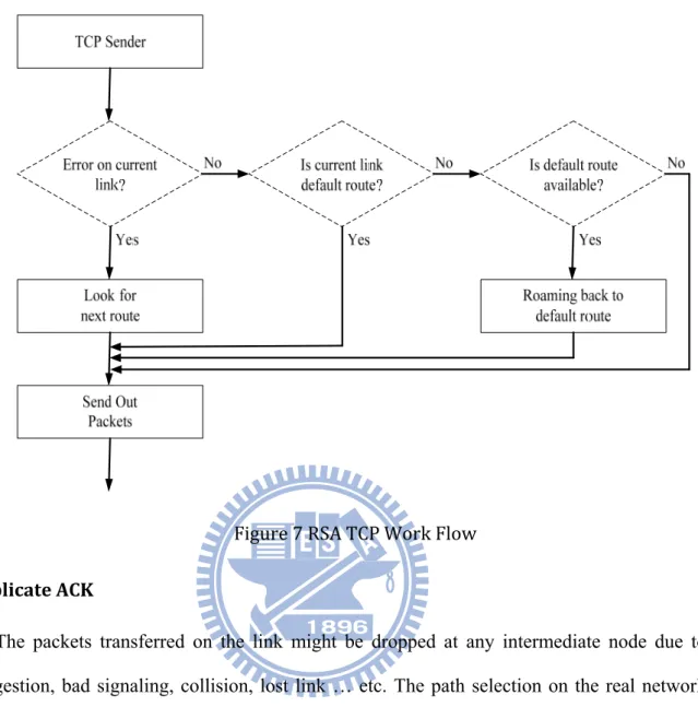
3.3.1 RSA Trigger Criteria
TCP protocol has its own state machine to control the traffic. There are two elements to be considered in review of TCP traffic control mechanism, Duplicate ACK and Timeout. Duplicate ACKs is a sign ahead of packet loss. And the packet loss is also a sign of connection having troubles. TCP performance will be much worse with packet loss. That means well processing the packet loss case can efficiently raise the utilization of TCP connection. If the packet response time is longer than the pre-defined timeout value, we say that the packet is expired. Timeout is a sign that the connection has big trouble now and might be not recovered.
The most common reason for packet loss is that the connection is down or the connection is congested. If the connection is down, the issue happened in the physical layer. This is a problem that the upper layer won’t be able to solve. As the connection is congested, the congestion might stay in a short time or keep in a long term. For above two reasons, dropping the current selected path and switch to a new healthy one may be a good solution.
23
Figure 7 RSA TCP Work Flow
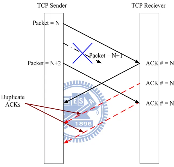
Duplicate ACK
The packets transferred on the link might be dropped at any intermediate node due to congestion, bad signaling, collision, lost link … etc. The path selection on the real network also changes the ordering for the packets. As shown in Figure 8, when the TCP sender receives the duplicate ACKs, TCP sender will try to send out one packet which might be lost on the link. Some TCP versions can re-send the lost packets as many as cwnd size allowed. If the duplicate ACK is caused by slightly dropped packets, the fast retransmission can cover this issue in one RTT. For packet re-ordering, TCP even has nothing to do with the issue, and the expected acknowledgement will arrive to the sender later. And, as long as the TCP sender can receive the duplicate ACK, this means the link should not be blocked or broken. If the link is really going down, the duplicate ACK packets will not be sent. After three duplicate ACKs received, TCP will trigger the fast retransmission to retrieve the condition as packet
24
lost. As explained above, the significance behind duplicate ACK is not necessary to give up the current connection. We need a more serious criterion to trigger our proposed method, which will not be activated at this condition to prevent too many unnecessary path switching.
Figure 8 Diagram for Duplicate ACKs
Timeout
As TCP finds that there are packets elapsing time larger than the timeout period, it is called packet timeout or packet expired. When packets are expired, that means the fast recovery and fast retransmission can not recover this phenomenon. There is a condition occurred on the network connection and can not be recovered by fast recovery mechanism.
25
This phenomenon might last for a while, and the most important thing of all is that TCP will enter slow-start, which decreases the TCP throughput. Now TCP is going to run at a very low data rate, so our proposed method might take over this time. As the TCP enters slow-start phase, the data rate is only 1 packet per second within this RTT. The data rate may be much far away from the range expected by users. So this is a very good time to execute our proposed method – Route State Aware Transport Control Protocol.
RSA TCP will give up the connection with trouble and try to transplant the whole configuration, status from current path to another path. In the worst case, the all new paths selected may also be congested. For users, data rate is equal to one packet per RTT after performing some new paths switching. The data rate is almost the same as the data rate starts from one packet per RTT without switching. So, RSA TCP starts to switch data packets to the backup path entirely and try to keep the performance unaffected by the congested link or blocked link. If there is no backup path to switch to or the new route is also congested, the last route will follow the TCP’s standard implementation to enter the original mechanism – slow-start.
3.3.2 How Polling Period Determined
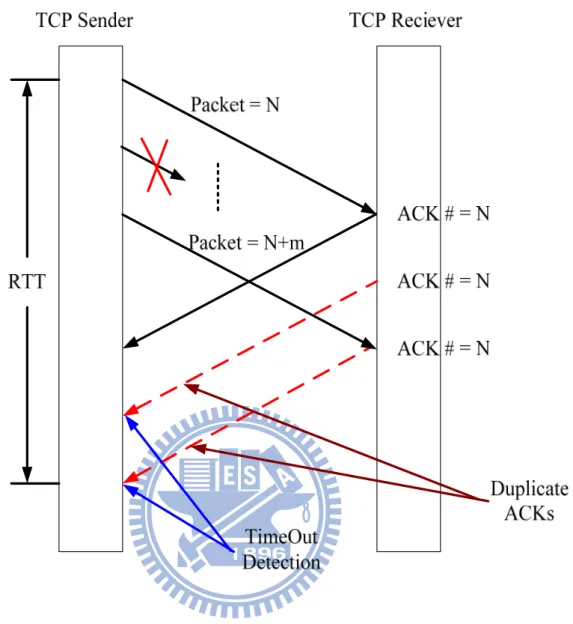
As shown in Figure 9, the timeout can be detected within a RTT. When the duplicate ACKs come back to TCP Sender, RSA TCP will look into the elapsed time that the packets have traveled. Assuming the timeout event is detected at any moment of the time that Figure 9 shows, the TCP will start to handle the duplicate ACKs event immediately. So RSA TCP has to handle the condition before next RTT ends.
As shown in Figure 11, we can use formula (8) to compute the real transmission delay (8)
26
in the topology. The transmission delay between Node 0 and ISP1-AP1 (same as ISP2-AP1) is illustrated in formula (9). The transmission delay is the same value between ISP1-AP1 and ISP1-AP2, so do ISP2-AP1 and ISP2-AP2.
The transmission delay between ISP1-AP2 and Node 1 is illustrated in formula (10) and the transmission delay between ISP2-AP2 and Node 1 is also having the same value in formula (10).
From formula (9) and (10), we can compute the total transmission delay from sender to destination side is formula (11).
Total One Way Transmission Delay = (9) * 2 + (10)
After computing the transmission delay, we can have the round trip time in the following formulas.
As table 4.1 illustrated, the Queue delay is 1ms for each node.
(9)
(10)
(11)
27
In summary, when there is timeout event occurred, RSA TCP has to update its routing information for the coming transport in 169.2ms. The polling period selection has to be smaller than 169.2 ms.
The polling period should not be longer than RTT. The detection might be not performed within one RTT. If the timeout occurs at this time, our proposed scheme can not activate to prevent TCP from entering the timeout recovery. Data rate is decreased after timeout recovery is active.
And, too short polling period brings heavy loading for system to poll the information. Summarily, the range between 100ms and 10ms is reasonable. We set polling period to 10ms in this proposed scheme.
28
Figure 9 Timeout Detection Timing
3.3.3 How RSA TCP works
RSA TCP only works on the host that has multiple interfaces. The interfaces should be enabled and connecting to network successfully. Each interface has its own IP and the related IP information of next hop. RSA TCP is located in transport layer which is higher than IP layer. So RSA TCP should require all IP information of active interfaces[20].
RSA TCP has to take one interface as default main trunk. After selecting the interface, the interface should be enabled and create a connection to the network service provider.
29
Confirm the connection which can deliver data successfully to the receiver side. Also, run a simple application to communicate with network service provider periodically to keep the connection alive, such as ping. And then select the next backup interface. Enable the interface and create a connection to the far end. Repeat the activities that performed on main trunk until all backup interfaces create their own connections successfully. The simple applications can help network service provider to keep the connection between host side and far end. Besides, the simple applications also help maintain the IP information including next hop information for RSA TCP to reference.
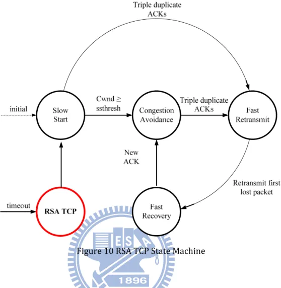
When RSA TCP gets packets timeout, RSA TCP will set a flag internally instead of entering slow start phase. NS2 simulator is also polling the flag every 0.01 second. As the flag is set, NS2 simulator will start to collect the next available path and transfer the data packets to the new path with replacing the next hop information only. There are 4 elements in socket pair, source IP/Port and destination IP/Port. To keep the flow to prevent doing 3-way handshaking again, RSA TCP only fills the new next hop IP inside the new packet. For receiver, all information to identify is kept. The receiver can parse the packets successfully even though the packets are coming from new source interface.
30
Figure 10 RSA TCP State Machine
Also, network layer needs a little modification. After RSA TCP is being triggered and starting to collect IP information of network layer, RSA TCP should store the next hop address of the selected interface and set an internal flag for network to reference. Before network layer filling the IP information into the packet, network layer should refer to the RSA TCP pre-set flag to determine which address should be filled. If the flag is not set, network layer should determine the next hop address according to the routing table and routing algorithm. If the flag is set to change next hop address, the stored address will be filled into the IP header before leaving.
After that, reset the flag. As long as the data path is changed, there is another mechanism to go back to default path. If there is no error occurred in the new path, NS2 simulator will transfer the data back to default path after 0.5 second. All relative parameters and flag are
31
clean. And the data is retrieved as the condition before error occurring.
Are the packets which are delivered on the new selected path recognized by the receiver? Referring to Figure 11, the format of TCP header, the changes of source IP will not appear in the header. When RSA TCP performs path roaming, the data packets on the new path will have the same TCP header as original path. Every field in TCP header was cloned for receiver to identify, such as source port, destination port, sequence number, acknowledgement number…etc. After the TCP header is parsing by the receiver, the data packets will be acceptable as same as delivered on the original path.
Two situations might be met after going back to the default path. First, the default path might still have troubles. So the data packets which are transferred back will be expired again. The expiration will inform RSA TCP to transfer the data from this path. This throughput is eliminated by this kind of transferring back to a path with errors.
Second, as shown in Figure 10, that is transferring data to a new path which might also have troubles before going back. The expiration triggers RSA TCP to find another path to backup transmission. If there is a new path to go, the RSA TCP will pick the new path up with higher priority. If there is no new path to select, the only one choice for RSA TCP to escape from this path is the default path. At this condition, RSA TCP has to stay at the path for a configurable period. The main purpose for RSA TCP to wait is to avoid too many unnecessary path switching and reduce the loading for original connection to be recovered. In this thesis, 0.5 second is selected.
32 TCP Sender Error on current link? Yes No Is current link default route? Yes No Look for next route Send Out Packets Is default route available? Yes No Roaming back to default route New path available? Yes No Stay 0.5 second Figure 11 Flow diagram of connection failure but no more new paths Figure 12 Format of TCP Header
33
4. Simulation Results
In order to demonstrate the performance of our proposed scheme, we use NS-2 (version 2.28) tool [16] with TCP module [17]. This module is implemented by National Institute Standards and Technology (NIST) to provide a platform for manipulation of network process. Many real-time applications, such as data, video and audio, have been available for experimental and practical uses. Not like traditional usage, TCP is also used as transport protocol to transmit real-time data packets.
For our proposed method, we need to generate the congestion on the network. As the congestion is getting worse enough, the proposed method will be active to function. That’s the reason why we inject traffic from a high bandwidth (100MB) to a low bandwidth (0.1M). And we need an independent path from source to the destination as the backup transport path. In normal condition, there might be a router in front of destination node, but the router will not affect the result. The two independent paths are connected directly from source to destination to reduce the redundant elements in the experimenting environment.
We had some scenarios to measure our proposed method. We list three configurations to be compared with. First is the ideal situation. TCP Vegas works at the full speed mode without any other injecting traffic to race the bandwidth. Second is the most popular situation. There is no backup route in the specific path. If any inter-node on the path is down, the path will be broken off and the packets cannot travel to the destination. The last, we do the experiment that implements our proposed method – RSA TCP. The best result of RSA TCP is equivalent to the result of first experiment.
In the experiment, the defined default route will be cut off in the middle way but the source node is not informed. The above three methods have their own mechanisms to deal
34
with the path failure. After a moment (10 seconds in this experiment), the connection is recovered and working again.
The result of first experiment is our goal to catch up. And the result of second experiment is the main target that the proposed RSA TCP has to achieve.
4.1 Scenario I
4.1.1 Network topology
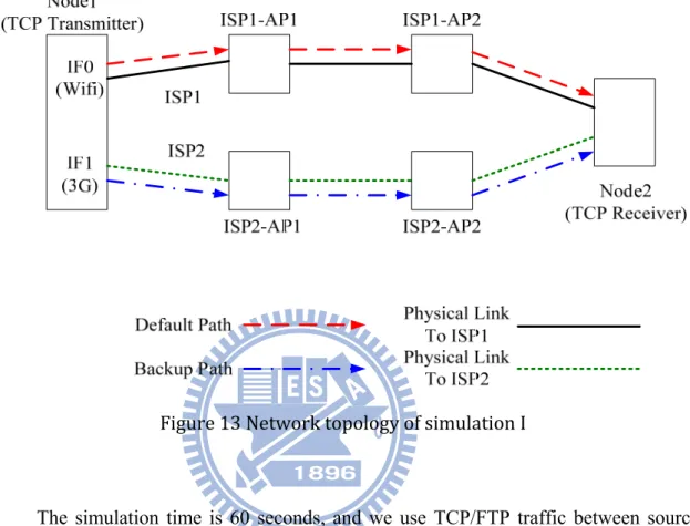
We would like to evaluate the performance with linking down and linking up to simulate that the last mile of Telecom or ISP is crashed and recovered. We create a network topology which has one host as TCP source. RSA TCP is performed on the TCP source which has multiple interfaces. Source side should decide that which interface or media is used as private main trunk. And then enable the physical link to the Internet service provider and also create a connection to assure the transmission. After that, select the backup interface and enable the other interfaces in the same way. So we also create two independent interfaces on the source node to connect to different networks. ISP1-AP1 – ISP1-AP2 construct an independent path to present an ISP link. So does the path ISP2-AP1 – ISP2-AP2. The framework is shown in Figure 13. In host side, we have to run some applications to communicate with Internet service provider to keep the connections alive. Do the same thing on the other backup interfaces before starting our experiment.
In Figure 13 each wired link has 100Mb bandwidth expecting the links to Node2, the links are ISP1-AP2 to Node1 and ISP2-AP2 to Node1. The bandwidths of these two paths are set to 0.1Mb to generate the congestion condition naturally. The packet propagation delay time is 1ms and all nodes use drop tail queue policy. TCP Vegas is
35
used to generate TCP data packets with 1000 bytes payload. The ISP1-AP1 and ISP2-AP1 play the role as the access point (next hop) for different media interfaces.
Figure 13 Network topology of simulation I
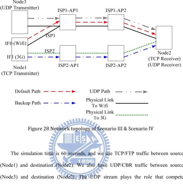
The simulation time is 60 seconds, and we use TCP/FTP traffic between source (Node1) and destination (Node2). The link between ISP1-AP1 and ISP1-AP2 will be down at time 20.0 second. The link between ISP1-AP1 and ISP1-AP2 will be up (re-connected) at time 30.0 second. The TCP/FTP traffic will be stopped at time 60.0 second.
Table 4.1 Parameters of simulation for Scenario I
Parameter Value Bandwidth Configuration
36 Node1 ÅÆ ISP2-AP1 100M ISP1-AP1 ÅÆ ISP1-AP2 100M ISP2-AP1 ÅÆ ISP2-AP2 100M ISP1-AP2 ÅÆ Node1 0.1M ISP2-AP2 ÅÆ Node1 0.1M Configuration Buffer Size 2 Protocol TCP Vegas Application Type FTP
Packet size 1000 bytes
Delay 1ms TCP Vegas α 1 TCP Vegas β 3 TCP Vegas γ 1 ISP1-AP1 Cost 1 ISP1-AP2 Cost 1 ISP2-AP1 Cost 1 ISP2-AP2 Cost 1
4.1.2 Simulation Steps
Time 0: Host starts TCP streaming to Destination.
The streaming starts from Node1 and goes through ISP1-AP1 and ISP1-AP2 to destination node.
Time 20: Link down the connection between ISP1-AP1 and ISP1-AP2.
37
way but the physical link to host is still alive.
Time 30: Link up the connection between ISP1-AP1 and ISP1-AP2.
Simulate the condition that the error on original selected route is recovered. The TCP traffic should be roaming back to this original default route. Time 60: Terminate the TCP traffic.
At Time 20.0 second, comparing RSA TCP with Full Speed, RSA TCP detects the link might be blocked. RSA TCP is updating the routing information immediately and starting roaming the data to the next routing path. At this time, there are already some packets traveling across the blocked connection. The packets are queued and processed in the nodes which are located on the default routing path. RSA TCP roams the data to the new routing path and the queues are empty. That means at this moment, RSA TCP packets can be queued by almost 2 paths. That’s the reason why the RSA TCP performance is a little bit better than no roaming.
At time 30.0 second, RSA TCP finds the best routing path is alive and starts to roam the following packets back to the previous routing path.
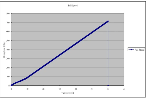
4.1.3 Simulation results – Scenario I + Full Speed TCP Vegas
In Fig. 14, the result shows the performance of the path which is not affected. We made the traffic run along the path from Node1, through ISP2-AP1, ISP2-AP2 and Node2. So the connection linking down of Router 3 and Router 4 at time 20.0 second and linking up at time 30.0 second does not matter to the selected path.
Before Time 10.0 second, the throughput is not a straight line. Referring to the
cwnd shown in Figure 15, it is very obvious to know that the TCP Vegas takes around
10 seconds to find out the best cwnd value, 2, on this connection. After time 10.0 second, the cwnd is no more changing. The throughput printed is a perfect straight line.
38
The total throughput of 60 seconds simulation is 714K bytes. Full Speed 0 100 200 300 400 500 600 700 800 0 10 20 30 40 50 60 70 Time (second) Thr oug hp ut ( kb ps ) Full Speed Figure 14 Scenario I: The simulation result of throughput in Full Speed mode Full Speed 0 2 4 6 8 10 0 10 20 30 40 50 60 70 Time (second) cw nd (pa cke t) Figure 15 Scenario I: The cwnd in Full Speed mode
39
4.1.4 Simulation results – Scenario I + Blocked TCP Vegas
In Fig. 16, the result shows the performance of the path which was ever blocked for 10 seconds. The traffic would like to run along the path from Node1, through ISP1-AP1, ISP1-AP2, to Node2 permanently. At the moment linking down at time 20.0 second, there traffic will exactly be stopped. At the moment linking up at time30.0 second, TCP will start from slow start. TCP needs time to reach the data rate before linking down. The total throughput of 60 seconds simulation is 553K bytes.
Before time 10.0, the TCP needs some time to look for the best cwnd value for this connection. Figure 17 shows how the cwnd value changes. After the link is re-connected at time 30.0 second, TCP endures a very long period without any acknowledgements. After reconnecting, TCP needs to restart and takes some time to compute the best data rate again. It takes around 2.6 seconds for TCP to reconstruct the data streams. The transition points to the throughput are very easy to map to the changes of cwnd in Figure 17. Blocked TCP 0 100 200 300 400 500 600 0 10 20 30 40 50 60 70 Time (second) Th rough put ( kbps) Blocked TCP
40 Figure 16 Scenario I: The simulation result of throughput in Blocked TCP Blocked TCP -2 0 2 4 6 8 10 0 10 20 30 40 50 60 70 Time (second) C w nd (pa cke t) Figure 17 Scenario I: The cwnd in Blocked TCP
4.1.5 Simulation results – Scenario I + RSA TCP
In Fig. 18, the result shows the performance of the path which is applied with our proposed scheme – RSA TCP. In the beginning, the traffic runs on default routing path - Node1, ISP1-AP1, ISP1-AP2, Node2 path. At the moment linking down at time 20.0 second, the RSA TCP is aware of the errors on the path and determining the backup path as new routing path with original configurations. After transferring to the backup path, the TCP needs to re-calculate the cwnd. But the long RTT period is not long enough to change the cwnd, the path is switching to the new one. And the speed is as fast as the original one. This reason makes cwnd no change while path switching. At the moment linking up at time 30.0 second, RSA TCP is triggered again due to finding out the pre-defined default route is alive. RSA TCP needs to transfer all packets with current configuration back to pre-defined default route. At roaming to the other path,
41
RSA TCP takes some time to determine the next path. So the TCP sender is silent at this period. Although RSA TCP is switching the traffic to the new one which has the same bandwidth as the original one, the throughput is still a little lower than ideal values.
In Figure 19, it is very obvious to see that unstable period for cwnd is longer than the formers. In the first 15 seconds, RSA TCP is trying to find out the best rate of the path. The RTT has huge variance in the initial phase and huge variance makes RSA TCP active. RSA TCP will roam the packets to the other path. At this time, some packets are delivered to the destination along with the previous path and some packets are delivered along with the new path. For data packets, the queues on both paths are filled with. That’s a temporary multipath phase.
Before time 10.0 second, RSA TCP has many opportunities to have short-term double buffers. Referring to Figure 18, the cwnd is configured to bigger than endurance of the connection. This makes packets timeout several times. RSA TCP is aware of this condition of timeout and starting to transfer the traffic to new path. In out experiment, there is no other traffic coexisting to race the queue buffer. After switching to a new path, the buffer will be fully used by RSA TCP. Double buffer benefits the performance in a short time. Why does the RSA TCP have worse throughput in a long run? Comparing to the RTT on previous path, the variance is much larger than former two experiments. The great variance makes the computation take more time to be stable. Referring to the result of cwnd, Figure 19, the cwnd after time 10.0 seconds is very close to best value but the cwnd is still larger than best value. This will not make the RSA TCP active due to the RTT being not large enough. The packets will be dropped and recovered very quickly by fast retransmission. There is no timeout event to trigger RSA TCP. RSA TCP spends lots of time retransmitting the dropped packets. That is the
42
reason why RSA TCP has better performance than Full Speed mode in the initial phase but becomes worse after all.
RSA TCP 0 100 200 300 400 500 600 700 800 0 10 20 30 40 50 60 70 Time (second) Thr oug hp ut ( kb ps ) RSA TCP Figure 18 Scenario I: The simulation result of throughput in our proposed method – RSA TCP RSA TCP 0 2 4 6 8 10 12 0 10 20 30 40 50 60 70 Time (second) cw nd (pa cke t)
43 Figure 19 Scenario I: The cwnd in our proposed method – RSA TCP mode Table 4.2 The result of three approaches with beta = 3 Method Item Ideal (No congestion) Static (Static) RSA TCP (Dynamic) Total Throughput 714K 553K 700K Throughput 0 100 200 300 400 500 600 700 800 0 10 20 30 40 50 60 70 Time (second) T hr oughput ( kbps ) Full Speed Blocked TCP RSA TCP Figure 20 Scenario I: The throughput comparison of the three approaches
4.2 Scenario II
4.2.1 Network topology
44
and β. We would like to grow up the range to try to enlarge the range of data rate. The data rate control mechanism is a very important advantage of TCP Vegas. Let’s experiment the condition that the data range is much higher than real bandwidth. The same topology is used in scenario II. The configuration is also the same expecting the TCP Vegas data rate control parameters, α and β. The value of α is no changed and β is increased from 3 to 30. Table 4.3 Parameters of simulation for Scenario II Parameter Value Bandwidth Configuration Node1 ÅÆ ISP1-AP1 100M Node1 ÅÆ ISP2-AP1 100M ISP1-AP1 ÅÆ ISP1-AP2 100M ISP2-AP1 ÅÆ ISP2-AP2 100M ISP1-AP2 ÅÆ Node1 0.1M ISP2-AP2 ÅÆ Node1 0.1M Configuration Buffer Size 2 Protocol TCP Vegas Application Type FTP
Packet size 1000 bytes
Delay 1ms TCP Vegas α 1
45 TCP Vegas γ 1 ISP1-AP1 Cost 1 ISP1-AP2 Cost 1 ISP2-AP1 Cost 1 ISP2-AP2 Cost 1
4.2.2 Simulation Steps
Time 0: Host starts TCP streaming to Destination.
The streaming starts from Node1 and goes through ISP1-AP1 and ISP1-AP2 to destination node.
Time 20: Link down the connection between ISP1-AP1 and ISP1-AP2.
Simulate the condition that the path selected was blocked in the middle way but the physical link to host is still alive.
Time 30: Link up the connection between ISP1-AP1 and ISP1-AP2.
Simulate the condition that the error on original selected route is recovered. The TCP traffic should be roaming back to this original default route. Time 60: Terminate the TCP traffic.
At Time 20.0 second, comparing RSA TCP with Full Speed, RSA TCP detects that the link might be blocked. RSA TCP updates the routing information immediately and starts roaming the data to the next routing path. At this time, there are already some packets traveling across the blocked connection. The packets are queued and processed in the nodes which are located on the default routing path. RSA TCP roams the data to the new routing path and the queues are empty. That means at this moment, RSA TCP packets can be queued by almost 2 paths. That’s the reason why the RSA TCP performance is a little bit better than no roaming.