-
Integral variable structure control approach for
robot manipulators
T.-L. Chern
Y.-c.
wuIndexing term: Control theory
Abstract: An integral variable structure control (IVSC) approach for robot manipulators is pre- sented to achieve accurate servo-tracking in the presence of load variations, parameter variations and nonlinear dynamic interactions. A procedure is proposed for choosing the control function so that it guarantees the existence of the sliding mode and for determining the coefficients of the switch- ing plane and the integral control gain such that the IVSC approach has the desired properties. Furthermore, a modified proper continuous func- tion is introduced to overcome the chattering problem. The proposed IVSC approach has been simulated for the first three links of a PUMA 560 robot arm as an illustration. The simulation results demonstrate the potential of the proposed scheme.
1 Introduction
Most industrial robots are composed of multilinks. Such a robot arm is a highly nonlinear system with complic- ated coupled dynamics and uncertainty (various loads, inertia, gravitational forces etc.). With regard to such a complicated system, various controllers have been devel- oped, such as adaptive controllers [l-31, robust control- lers [ 4 6 ] and controllers based on the theory of variable structure [7-lo].
The integral variable structure control (IVSC) approach previously proposed in Reference 11 considered the single-input single-output (SISO) system and has been successfully applied to electrohydraulic servo control systems. The IVSC approach comprises an integ- ral controller for achieving a zero steady-state error under step input and a variable structure controller (VSC) [12-141 for enhancing the robustness. With this special scheme, two control loops are obtained, and it yields improved performance when compared to conven- tional VSC and linear approaches [ll]. This paper extends previous results to the multi-input multi-output (MIMO) case, with an application to robot manipulators. The control of the first three links of a PUMA 560 robot arm has been simulated for illustrating the design pro- cedure and demonstrating the robustness property.
Paper 8569D (C9, ClS), first received 21st January and in revised form 13th November 1991
T.-L. Chern is with the Institute of Electronics, National Chiao Tung University, Hsinchu, Taiwan, Republic of China
Y.-C. Wu is with the Institute of Control Engineering, National Chiao
Tung University, Hsinchu, Taiwan, Republic of China IEE PROCEEDINGS-D, Vol. 139, No. 2, MARCH 1992
2 Description of methodology
The IVSC approach presented here is derived for the class of second-order dynamic equations with a positive- definite symmetric inertia matrix. Since the dynamics of most mechanical systems can be modelled in this form, this approach will have wide applications.
Consider the dynamic equation [9]
M ~ + B ~ + D o = W + U ( 1 4
where 0,
8,
d
are n x 1 position, velocity and acceleration vectors, respectively; M = M ( 0 ,8)
is an n x n symmetric positive-definite inertia matrix; B = B(0,8)
is an n x n matrix; D = D(0,8)
is an n x n matrix; W = W(8,8)
is an n x 1 vector representing the gravity term; and U is an n x 1 control vector.The corresponding state-space model can be written as
+ [;-,]U +
[JW
The proposed configuration of the IVSC approach is shown in Fig. 1. It combines an integral controller, a
integral
cont io1 ler
Fig. 1 Block diagram of an integral-variable-structure-controlled manipulator control system
VSC and the plant (eqn. I), and is described as follows: I
where Bd =
[q:e",
.
.
.
e]'
represent the desired position; Z = [zIz2 ..
2.1'
is an n x 1 vector; I is the n x n iden- tity matrix;K,
= diag &k2.
' . k,] is the gain matrix of 'the integral controller; and the control function U = [U, U ,
.
.
. U,JT is piecewise linear of the formU:(x, t ) if ui > 0 .
U ; ( x , t) if ui > 0 1 = 1,
...)
n (3) 161where ui is the ith component of the n-dimensional switching plane U = 0 and is chosen as
(44 (4b) ui = cAOi - k i z i )
+
di
U = C(0 - K , Z )+
d
U = [UlU2 ' . ' U"]T i = 1,. . .
, n or, in matrix form,where
C = diag [clcz
. . .
c,] ci > 0Design of such a system involves
(a) the choice the functions U + and U - to guarantee the existence of a sliding mode
( b ) the determination of the switching function U and the integral control gain K , , such that the system has the desired eigenvalues
(e) the elimination of chattering of the control input. 2.1 Control function
From eqns. 2 and 4, one has ir = - M - ' D @ - M-'Bd
+
Cd -c~,(fY
-e) +
M - ~ W+
M - ~ U (5) Let M = M O + A M B = B O + A B D = D O + A D W = W o + A Wwhere MO, Bo, Do and W o are nominal values of M , E , D and W , and A M , AB, AD and A W are the deviations.
Let the control function U be decomposed as
U = U,,
+
AU (64where U , , , called equivalent control, is defined as solution of the problem U = 0 under M = MO, B = D = Do and W = WO. That is,
U,, = Do@
+
BO8 - M°Cd+
MOCK,(@ - U ) - W othe BO,
The function AU is used to eliminate the influence due to the plant parameter variations in A M , AB, AD and A W so as to guarantee the existence of a sliding mode. It is constructed as follows: AU = MOAT ( 6 4 AT =
~ ( e
- K , Z )+
@d
+
cp ( 6 4 Y =diag [YlY2...
Y J @ = diag [m1D2 ... O n ] whereFor a mechanical system such as a robot arm, each diagonal component of M - ' M o is larger than the absol- ute value of the sum of other components in the same row
[lo].
Thus, the following equation is obtained:M - ' M o = I
+
AI (7)where AI = [Aiij] (i = 1,
...,
n, j = 1, _.., n ) and each entry Aiij<
1.The condition for the existence of a sliding motion on the ith switch plane is [12-141
lim u i ui < 0
Ci'O
Substituting eqn. 6 into eqn. 5 yields
iri = - M - ' ADO - M - '
ABB
- AICO+
AICK(Od - U )+
M - ' A W+
AI AT+
AT Let A W = [ A w l ,...,
M - ' = [m;'] M - ' AD = [Adij] M - ' A B = [Abij] (i = 1,...,
n, j = 1,...,
n) ( i = 1,...,
n, j = 1, ..., n) ( i = 1,...,
n, j = 1,..., n)
Each component of ir is represented asiri = (- Adi, - Aiii ci - Aiii ci ki)(Oi - ki zi) - Abii8
+
g i+
AT,= (- Ad,, - Aiii ci - Aiii ci k i
+
Yi)(Oi -ki
zi)+
( - Abii+
@ i ) B+
(si+
vi) (94where
g i = - x ( A d i j
+
A i i j c j+
AiijcjKj)Oj - C ( A b i j d j )j t i j + i
n
+
C ( A i i j c j K j 8 ; ' + m ; ' A w j ) + C ( A i i j A z j ) - (Adii+
Aiii ci+
Aiii ci K i ) K i Zij = 1 j = 1
( 9 4 Then
lim iri ui = (- Adii - Aiii ci - Aiii ci ki
+
Yi)(Oi - kizi)ui ai-0+
(- Abii+
@ J d i 0;+
(8,+
cpibi (10) and the conditions for satisfying the inequality eqn. 8 areY t < inf (Adii
+
Aiiici+
Aiiiciki)Y; > sup (Ad,,
+
Aiii ci+
Aiii ci ki) if (Ui - ki zi)ui > 0if
(ei
- k, zi)oi < 0i = 1 ,
...,
n (lla)Y i =
@: < inf (Ab,,) if
4,
ui > 0@; > sup (Abii) if 8,ui < 0 i = l ,
...,
n ( l l b )mi
=cp+<inflg,l i f u i > O
.
I = 1,
...,
n ( l l c ) Note that g, in eqn. 9b is dependent not only on param- eter variations, load variation and coupling effects but also on the control parameters c j , K j ,AT^
( j = 1, ..., n). Since the plant parameter variations Adij, Abij, Awi (i = 1, ..
., n, j = 1,..
.,
n) are bounded and the term Ai,(i = 1,
.
. ., n, j = 1,. .
., n) 4 1 as described in eqn. 7, one{
cp; > s u p l g , l i f u i < O cp = C c p , c p 2 " ' V"1' Y: if(ei
- kizi)ai > 0 , I = 1, ..., n Y g = { Y ; if(ei
- kizi)ui < 0 i = 1,...,
ncan guarantee the existence of the gain qi such that the inequality eqn. 1 I C is held.
2.2 Determination of switching plane and integral control gain
While in the sliding motion, the system described by eqn. 2 can be reduced to the following linear equations [12- 141 :
8
= -C(O - K , Z )(W
i = @ d - @ (12b)
Since C and K, are diagonal matrices, the MIMO system can be decomposed into n sets of SISO systems, as follows:
[ : ] = [ I : i
ct][:]+[y]O:
i = l ,...,
n (13) The closed-loop transfer function of the system described by eqn. 13 iswhere OAS) and @(S) are the Laplace transforms of Oi and f$', respectively. The characteristic equations of the systems are
S2 + c i s
+
ciki = 0 i = 1, ..., n (15)Since these characteristic equations are independent of the plant parameters, the IVSC approach is robust to the plant parameter variations. It can achieve a zero steady- state error, and its eigenvalues can be set arbitrarily. Let the desired eigenvalues of the systems be A l i , 1 2 4 = 1,
. . .
, n), or the equivalent desired characteristic equationsS2
+
+
a2i = 0 i = 1 , ..., n (16)Then the switching plane coefficients ci ( i = 1,
. . .
, n - 1) and the integral control gains ki (i = 1 , . .. , n) can be chosen as follows:ci = U l i
ki = U 2 J U l i
2.3 Chattering considerations
For the control law given by eqn. 6d, if Y i ,
mi
and cpi ( i = 1 ,. . .
, n) are chosen as y. = y: = -y: Q i = Q: = -@: and cp. = cp? = -cp. I ,then the control function Ari (i = 1,
. .
.
, n) can be rep- resented asA ~ ~ = ( Y ~ l @ ~ - k ~ z ~ l
+cDi181
+cpi)sign(ui) (17) Since the control Asi contains the sign function sign (ui),direct application of such control signals to the plant may give rise to chattering. To obtain continuous control signals, the sign function sign (ui) in eqn. 17 can be replaced by a modified proper continuous function as Cl11
'Ji
Pi@,) =
-
I'Jil
+
6iwhere di is chosen as a function of
1
Bi - astii = d l i
+
6,il@i -@'I
i = 1,...,
n (19) where 6,, and 6 2 i are positive constants.3
The PUMA 560 robot arm has six links and six rota- tional joints. However, for simplicity, it is assumed that the wrist joints are not active. The mathematical model of the first three links of the PUMA 560 robot is given by
Control of first three links of P U M A 560 robot arm
Cl61
M(0)Q
+
B(0,8)8
= W(O,8)
+
U (20)where 0 E R 3 , U E R3, W(0,
8)
E R', M ( 0 ) E R 3 x 3 and B(0,8)
E R j X 3 .Based on the block diagram shown in Fig. 1, by com- bining eqn. 20 and the IVSC, one obtains a set of state equations of the integral-variable structure-controlled three-link manipulator control system, as follows:
[SI=[-!
SI-:- I 0:]I:]
0+
[
{-.Iu
+
[
{-.Iw
+
[;]e
(21) where Od =[e",e", e",]'
represents the desired position, Z = [z,z2z,]' is a 3 x 1 vector, I is 3 x 3 identity matrix, and K, = diag [k,k2 k,] is the gain matrix of the integral controller. When following the design procedure described in Section 2, one obtainsU=U,,+AU = 8'8 - M o d
+
MOCK,(@ - 0) - WO+
MO AT (22) where ' J i Pi(Oi) =1
U i )+ +
a,,
I
Oi -e
I
The control gains are chosen, according to eqn. 11, as Y i = = - Y ; < - supIAiiici
+
AiiicikiIi = 1, 2, 3 (23a) (23b)
mi
= @: = -Q; < - supI
AbiiI
i = 1, 2, 3 andcpi = cp+ = -cp; i - sup (giI i = 1 , 2, 3
U = C(0 - K , Z )
+
8
(234
(24) The U function is obtained from eqn. 4 as
163 IEE PROCEEDINGS-D, Vol. 139, No. 2, MARCH 1992
In the sliding motion, the system described by eqn. 21 can be reduced to the following simple linear form:
(25a) (25b) Since C and K, are diagonal matrices, the MIMO system
and
U = [ c , u ~ = C(O - K , Z )
+
4
The simulation results of the dynamic responses are plotted in Figs. 2-6. To examine the robustness property
8
= - C(O - K , Z ) Z = O d - 0can be decomposed into three SISO systems, as follows: 1.2
1.0 0.8
.
0.6 0.4[:]
=[I:
ct][:]
+
[:]e
i = 1 , 2 , 3 (26) UThe characteristic equations of the system are .?
Sz + c i s
+
c i k i = 0 i = 1, 2, 3 (27) mIt is clear that the dynamic performance of the system can now be determined by simply choosing the coeff- cients c1, c,, c, and the gains k,, k , , k , . Let the charac-
l l i and l Z i be 0
0.2
teristic equation of the system with desired eigenvalues 0' 0.1 0.2 0.3 0.4 0.5 0.6 0.7 0.8 0.9 1.0
s2
- (Ali+
AZi)S+
L l i A Z i = 0 (28) Then, ci and ki can be chosen asci = -(Ali
+
A,J1.2
I
0 4 t
I
4 Simulation results and discussions
The robustness of the proposed IVSC approach against large variations of plant parameters and load have been simulated for demonstration. The nominal values of the PUMA 560 robot are taken from Reference 16 and given in Table 1, in Appendix 7.
Choosing the eigenvalues of the systems of eqn. 26 as l l i = -20 + j l 5 A z i = -20 - j l 5 i = 1, 2, 3 one obtains the coefficients of the switching plane and the integral control gain given by eqn. 29 as
K = diag C15.625 15.625 15.6251 (304
C = diag [40 40
401
(304The gains Y i ,
mi
and ' p i must be chosen to satisfy eqn. 23,and, based on simulations, one possible set of the switch- ing gains is chosen as follows:
Y = diag [-SO0 - 500 - 5001 Q = diag [ - 10 - 10 - lo] cp = [ - 1 - 1 - 13= ( 3 1 4 ( 3 W ( 3 1 4 and
Thus, the IVSC design gives a control function U = U,,
+
AU= - M ° C 8
+
M0CK,(Bd - 0) - WO+
MOAT
where C, K , , Y , @ and cp are given in eqns. 3G-31, andAT = (YI 0 - K , Z I
+
@ I
81
+
cp)P where P = C P l ( 4 P 2 ( ~ ) P 3 ( U ) l T in which Ui P,(U,) = ~ u i ~ + O . l + l O ~ o i - ~ ~ 0'1 0'2 0'3 0'4 0'5 0 6 0 7 0'8 0'9 1'0 b S C Fig. 2 0.1+
I O I X , ~ ~ 1 a n d i n p u t c o " n n d d = [ l I I l r a d + zero load +. . Y Response 0, b ResponseB, c Response 0,Angular responses of IVSC approach with function piu,), 6 , =
with load (200% change in m, and 500% change in gyration radius)
of the control system, assume that there is a load attached to the end effector and the total mass and gyra- tion radius of the arm are m 3 = 15.03, k3xx = 0.0906, k3,,,, = 0.093 and k3== = 0.0126. This corresponds to an increase of 200% in mass and 500% in the gyration radius of the third link. The three links angle responses are shown in Figs. 2 and 3. It is clear that the response can almost be maintained under severe variations of the plant parameters and load.
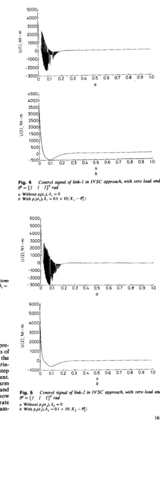
Figs. 4-6 show the waveforms of the control function of three links with zero load. It is clear that the chattering
IEE PROCEEDINGS-D, Vol. 139, N o . 2, MARCH 1992
164
phenomena can be eliminated by using a modified proper continuous function, Thus, the IVSC approach seems amenable for practical implementation.
'.
06 m-0 4o.21i
'0"
01 0 2 0:3 0 4 0:5 0 6 0 7 0 8 0 9 1'0 0 0.4t i
' 0 0.1 0.2 0.3 0.4 0.5 0.6 0.7 0.8 0.9 1.0 b 5 CFig. 3 Angular responses of IVSC approach under random deviations of m, from 0 to 200%, gyration radius from 0 to 500%, with p i a ) , hi =
0.1
+
I O [ X , - @ [ andinput command$ = [ I (1 Response 8 , b Response 0, c Response 8, I I ] rad 5 ConclusionsAn IVSC design methodology for MIMO system is pre- sented and applied to the control of the first three links of a PUMA 560 robot arm. It has been shown that the IVSC approach is robust to the plant parameter varia- tions. It can achieve a zero steady-state error for step input and is possible for arbitrary eigenvalue assignment. The control of the three links of a PUMA 560 robot arm is considered for demonstrating the design procedure and the potential of the IVSC approach. Simulations show that the proposed approach can give an almost accurate servo-tracking response in the face of large plant param-
IEE PROCEEDINGS-D, Vol. 139, N o . 2, MARCH 1992
eter variations, load variations and nonlinear dynamic interactions. It is a robust and practical control law for robot manipulators. 5000 3000 0 4500 4000 3500 3000 2500 2000' 1500- 1000- 500 - 0- -5000 o< 0 3 0.4 015 0.6 017 018 0 9 1 h 5 b Fig. 4 @ = [ I I 1lTrad (I Without piu ) S - 0 b Witbp,(c,'),~,'~O~l + IOJX, - e l
Control signal of link-1 in IVSC approach, with zero load and
6000 3000 0 6000 50001 4000
::::I
1000 0 0.1 0.2 0.3 0.4 0.5 0.6 0.7 0.8 0.3 1.0 -1000 S b Fig. 6 @ = [ I 1 /]'radControl signal of link-2 in IVSC approach, with zero load and
D Without p2(u2). 6, = 0
b Wilhp,(u,),S,=O.l
+
l O l X , - ~ l165
2000 2500
20001
- -500 1500-
-
=.
1000 0-
500 -10001 ’ ’ ’ ’ ’ ’ ’ ’ , A 0 0.1 0.2 0.3 0.4 0.5 0.6 0.7 0.8 0.9 10 -500!l 0:l 0:2 0:3 0:4 0:5 0:6 0 7 018 019 l b U Fig. 6 e “ = [ ] 1 Il’radControl signal of link-3 in IVSC approach, with zero load and
a Without p,(u,), 6, = 0 b With p&,), 6, = 0.1 + 101 X , -
S:
I 6 References1 KOIVO, A.J., and GUO, T.H.: ‘Adaptive linear controller for
robotic manipulator’, IEEE Trans., 1984, AC-28, pp. 162-171
2 SINGH, S.N.: ‘Control and stabilization of a nonlinear uncertain elastic robotic arm’, IEEE Trans., 1988, AFS-24, pp. 114-123
3 KIM, G.K., and SHIN, K.G.: ‘An adaptive model following control of industrial manipulator’, IEEE Trans., 1983, AFS-19, pp. 805-814
4 SINGH, S.N., and SCHY, A.A.: ‘Robust trajectory following control of robotic system’, J. Dynamic Systems, Measurement and Control,
1985,107, pp. 30&315
5 HA, I.J., and GILBERT, E.G.: ‘Robust tracking in nonlinear systems’, IEEE Trans., 1987, AC-32, pp. 763-771
6 SINGH, S.N., and SCHY, A.A.: ‘Control of elastic robotic system by nonlinear inversion and modal damping’, J. Dynamic Systems, Measurement, and Control, 1986,108, pp. 18&189
7 YOUNG, K.D.: ‘A variable structure model following control design for robotics applications’, IEEE Trans., 1988, RA-4, pp.
55G561
8 SINGH, S.N., and ZAKHARIA, Y.N.: ‘Variable structure control of a robotic arm in the presence of uncertainty’, J. Robotic Syst., 1989,
6, pp. 111-132
5
b
9 YEUNG, K.S., and CHEN, Y.P.: ‘A new controller design for manipulators using the theory of variable structure systems’, IEEE Trans., 1988, AC-33, pp. 200-206
10 HASHIMOTO, H., MARUYAMA, K., and HARASHIMA, F.: ‘A microprocessor-based robot manipulator control with sliding mode’, IEEE Trans., 1987, IE34, pp. 11-18
1 1 CHERN, T.L., and WU, Y.C.: ‘Design of integral variable controller and application to electrohydraulic velocity servo systems’, IEE Proc. D, Control Theory & Appl., Sept. 1991, pp. 4 3 9 4 4 4
12 UTKIN, V.I.: ‘Variable structure systems with sliding modes’, IEEE Trans., 1977, AC-22, pp. 212-222
13 UTKIN, V.I.: ‘Sliding modes and their application in variable struc- ture system’ (Mir, Moscow, 1978)
14 ITKIS, U,: ‘Control systems of variable structure’ (John Wiley, New York, 1976)
15 AMBROSINO, G., CELENTANO, G., and GAROFALO, G.: ‘Variable structure model reference adaptive control system’, Int. J. Contr, 1984,39, pp. 1339-1349
16 TARN, T.J., BEJCZY, A.K., YUN, X., and DING, X.: ‘Dynamic equation for PUMA robot arm’. Dept. of Systems Science & Mathe- matics, Washington University, St. Louis, Missouri 63130, USA, Robotics Lab. Report SSM-RL-85-02, 1985
7 Appendix
Table 1 : P U M A 580 robot arm mrameters with zero load
-____ -
Reflected Link Mass Centre of mass Radius of gyration
~ motor inertia m , h ) i , ( m ) VAm) f,(m) C x ( m z ) k:,,(m2) k:,(m2) /.,(kg/m’) 1 1296 00000 03088 00389 01816 00152 01811 07766 2 2237 -03289 00050 02038 00596 01930 01514 23616 3 501 00204 00137 00037 00151 00155 00021 05827 a , = 0 4318 m, a 3 = -0 0191 m, d, = 0 1505 m, d, = 0 4331 m
166 I E E PROCEEDINGS-D, Vol. 139, No. 2, MARCH 1992