國
立
交
通
大
學
資訊科學與工程研究所
碩
士
論
文
藉由減少 HARQ RTT 來增進 TCP 在 LTE 中的表現
Improving TCP Performance by reduction of HARQ RTT
研 究 生:武冠中
指導教授:王協源 教授
藉由減少 HARQ RTT 來增進 TCP 在 LTE 中的表現
Improving TCP Performance by reduction of HARQ RTT研 究 生:武冠中 Student:Kuan-Jong Wu
指導教授:王協源 Advisor:Shie-Yuan Wang
國 立 交 通 大 學
資 訊 科 學 與 工 程 研 究 所
碩 士 論 文
A ThesisSubmitted to Institute of Computer Science and Engineering College of Computer Science
National Chiao Tung University in partial Fulfillment of the Requirements
for the Degree of Master
in
Computer Science
November 2012
Hsinchu, Taiwan, Republic of China
藉由減少 HARQ RTT 來增進 TCP 在 LTE 中的表現
研究生:武冠中 指導教授:王協源
國立交通大學 資訊科學與工程研究所 碩士班
摘 要
在科技的進步下,伴隨著智慧型手機和平板電腦的推陳出新,行動網路已經 如同固網般,是大多數人不可或缺的生活必需品,而網路的品質更是使用者在意 的重點。 近年來由 3GPP 推行的 LTE 架構,已經在世界各地如北美、南韓、日本鋪設, 新一代可連接 LTE 的 3C 產品更已開始量產銷售,可以看出 LTE 已成為新一代行 動通訊技術的主導者。 儘管 LTE 在通訊架構與天線技術上有所進展,但在終端設備與基地台上仍需 要大量時間做資料處理。對於 TCP 使用者來說,不僅增加了 RTT 同時也減少了傳 輸速率,是使用者不樂於見到的。 關於這點,我們提出了一個以原架構為基礎的辦法,試圖減去 LTE 中的 HARQ 所帶來的 RTT,藉以增加傳輸速率。研究成果也顯示了新架構在特定環境下,對 於傳輸速率是有益處的。ii
Improving TCP Performance by reduction of HARQ RTT
Student: Kuan-Jong Wu Advisor: Shie-Yuan Wang
Institute of Computer Science and Engineering
Nation Chiao Tung University
Abstract
As the progress of technology, with rapid substitution of smart phone and pad devices, the role of mobile communication network almost equals to the cable network, and becomes necessary in citizen’s daily life. The network quality is the factor that users care about mostly.
In recent years, LTE telecommunication system propelled by 3GPP is spread over North America, South Korea and Japan, and the new generations of 3C products are also equipped with LTE chips. We can know that LTE has become the leader of new telecommunication technology.
Although LTE has made progress in communication architecture and antenna technology, it still needs time to process data in terminal devices and base stations. For TCP data user, the processing time not only increases TCP RTT but also decreases transmission throughput, which users don’t expect for.
For this point, we propose an idea based on the original architecture, trying to eliminate the RTT brought by HARQ in LTE for increasing transmission throughput. The research results do show that in some constraint environments, the idea has benefits on transmission throughput.
Acknowledgements
Firstly, I have to appreciate my adviser, Prof. Shie-Yuan Wang. He assigned a research topic which is difficult for me, and when I had a problem which was
unsolvable to me, he also led me to think, looked inside, and then solved it. Through the difficult topic, I become much more humble to this world and people, and I have learned the right attitude on solving problem by my teacher’s leading.
Secondly, I need to thank Prof. His-lu Chau and Sau-hsuan Wu. They are willing to spend time being my thesis oral defense commissioners. They give me useful advices to make my thesis more sufficient.
Besides, I want to say thanks to my friends and lab members who always support me. They cheer me up when I was down, and give me suggestions when I was
confused. I feel satisfied to have those friends.
Lastly and the most importantly, I appreciate my parents, my family, and my relatives. They are always my backup and always care about me. I just can’t wait to share my accomplishments with them.
iv
Contents
摘 要... I ABSTRACT ... II ACKNOWLEDGEMENTS ... III CONTENTS ... IV LIST OF FIGURES ... VI LIST OF TABLES ... VIII1. INTRODUCTION ... 1
2. BACKGROUND ... 2
2.1 EstiNet ... 3
2.1.1 Graphical User Interface... 3
2.1.2 Kernel Re-entering Engine ... 4
2.1.3 Module-based Architecture ... 5
2.2 LTE ... 8
2.2.1 LTE Topology ... 8
2.2.2 E-UTRAN Protocol Stacks and Channel Mapping ... 10
2.2.3 E-UTRAN Dataflow ... 12
2.2.4 HARQ... 16
2.2.4.1 HARQ Entity ... 16
2.2.4.2 HARQ Process ... 17
2.2.4.3 HARQ Process Number ... 18
3. RELATED WORK ... 21
4.1 New Design Architecture... 23
4.2 Implementation ... 24
4.2.1 HARQ Implementation ... 24
4.2.2 Generate Fake TCP ACK... 26
4.2.3 DataQ-AckQ control mechanism ... 27
5. PERFORMANCE EVALUATION ... 29
5.1 Simulation Environment ... 29
5.2 Case1 – Greedy TCP ... 30
5.3 Case2 – Small Webpage Download ... 40
5.4 Case3 – Saving UL Bandwidth... 47
6. CONCLUSION ... 48
7. FUTURE WORK ... 49
vi
List of Figures
Figure 2-1 Snapshot of EstiNet GUI ... 4
Figure 2-2 Kernel re-entering methodology ... 5
Figure 2-3 Module-based architecture ... 6
Figure 2-4 Overview of simulation flow ... 7
Figure 2-5 Communication between modules ... 7
Figure 2-6 LTE Network Topology ... 9
Figure 2-7 E-UTRAN Protocol Stack ... 10
Figure 2-8 Channel Mapping ... 12
Figure 2-9 Layer2: IP Packet to TB ... 13
Figure 2-10 Layer1: TB to Codeword ... 13
Figure 2-11 Layer1: Codeword to Physical Resources ... 14
Figure 2-12 Physical Channel Procedure ... 15
Figure 2-13 Relationship between HARQ entity and HARQ processes ... 17
Figure 2-14 HARQ RTT ... 19
Figure 3-1 Related Work Architecture ... 22
Figure 4-1 Proposed Architecture ... 24
Figure 4-2 Implementation topology ... 24
Figure 4-3 HARQ implementation flowchart at Tx Side ... 25
Figure 4-4 HARQ implementation flowchart at Rx side ... 25
Figure 4-5 Generating Fake TCP ACK Packet ... 27
Figure 4-6 Pseudo code of DataQ-AckQ control mechanism ... 28
Figure 5-1 Simulation Environment ... 29
Figure 5-2 Case1 Result: Link Delay 5 ms ... 30
Figure 5-3 Case1 Result: Link Delay 10 ms ... 31
Figure 5-4 Case1 Result: Link Delay 15 ms ... 31
Figure 5-5 Case1 Result: Link Delay 20 ms ... 32
Figure 5-6 Case1 Result: Link Delay 25 ms ... 32
Figure 5-7 Case1 Result: Link Delay 30 ms ... 33
Figure 5-8 Case1 Result: Link Delay 50 ms ... 33
Figure 5-9 Case1 Result: Link Delay 100 ms ... 34
Figure 5-10 Case1 Result: BER 0 ... 34
Figure 5-11 Case1 Result: BER 1/10^6 ... 35
Figure 5-12 Case1 Result: BER 1/10^5 ... 35
Figure 5-14 Case1 Result: BER 1/10^3 ... 36
Figure 5-15 Case1 Result: BER 1/10^2 ... 37
Figure 5-16 Case1 Explanation: RTT and Window Size ... 38
Figure 5-17 Case1 Explanation: DataQ and AckQ ... 39
Figure 5-18 Case1 Explanation: Throughput ... 39
Figure 5-19 Case1 Explanation: RTT and AckQ Overlapping ... 40
Figure 5-20 Case2 Result: Link Delay 5 ms ... 41
Figure 5-21 Case2 Result: Link Delay 10 ms ... 41
Figure 5-22 Case2 Result: Link Delay 15 ms ... 42
Figure 5-23 Case2 Result: Link Delay 20 ms ... 42
Figure 5-24 Case2 Result: Link Delay 25 ms ... 43
Figure 5-25 Case2 Result: Link Delay 30 ms ... 43
Figure 5-26 Case2 Result: Link Delay 50 ms ... 44
Figure 5-27 Case2 Result: Link Delay 100 ms ... 44
Figure 5-28 Case2 Result: Webpage Size 100KB ... 45
Figure 5-29 Case2 Result: Webpage Size 80KB ... 45
Figure 5-30 Case2 Result: Webpage Size 60KB ... 46
viii
List of Tables
Table 2-1 TDD DL/UL configuration ... 19 Table 2-2 HARQ Process Stop-and-Wait Scenario ... 20
1. Introduction
LTE is prevalent in telecommunication nowadays, and HARQ also takes an important part in LTE. Even in this high-tech network, there still have data processing time in base stations and terminal devices, which increases RTT. As we know, RTT is negative proportion of TCP throughput. We try to eliminate RTT affected by HARQ to increase throughput.
In chapter 2, we introduce LTE networks and HARQ procedures, and in chapter 3 we talk about related work which our proposed architecture is based on. Then we will elaborate on the proposed architecture in Chapter 4 and evaluate the performance in Chapter 5. Lastly, we will make a conclusion in Chapter6 and describe future work in chapter 7. Reference is in Chapter 8.
2
2. Background
In recent years, mobile network has been the popular issue in telecommunication technology as more and more smart-phones, pads, etc. appear in our daily life, and the most significant factors which users can feel sensibly are the data transmission rate and price.
LTE is one of the 4G telecommunication technologies of high rate data
transmission, providing 100Mbit/s on DL and 50Mbit/s on UL, for mobile phones and data terminals. LTE standard is specified by 3GPP organization, and its first release year is 2008, which is still under amendment. Until now LTE is spread in many areas such as North America, South Korea, etc.
In addition to the higher data transmission rate, LTE is downward compatible to UMTS and GPRS telecommunication network, which decreases the effort and complexity to integrate all the customers’ groups.
However, establishing a LTE network is still costly, on the other hand, network simulator is a cheaper way to construct the environment and do further research based on the simulation results.
There are many network simulators in the world, such as OPNET, QualNet, NS-3, and EstiNet. Here we choose EstiNet simulator as our tool because EstiNet can generate dataflow close to the real world by its powerful simulation engine design.
We will introduce EstiNet and LTE respectively to let the reader get the basic knowledge in this thesis below.
2.1 EstiNet
EstiNet network simulator is a commercialized product which is evolved from open source NCTUns network simulator, and EstiNet’s copyright is hold by a start-up company, EstiNet Technology, since late 2011.
Transferring to a commercial version, EstiNet not only adds more functionality, but also still inherits the main attributes of NCTUns, like graphical user interface (GUI), kernel re-entering engine, and module-based architecture.
All of the above attributes can also be seen as attractive advantages of EstiNet, bringing more user-friendly experience and much closer to the real world dataflow. We will talk about these advantages briefly in chapter 2.1.
2.1.1 Graphical User Interface
With GUI, users can plot or modify network topology quickly and conveniently, eliminating tedious coding and saving time. Especially when we need a complex network environment, we can feel more about the convenience that GUI brings to us. When reviewing the simulation results, GUI also exhibits dataflow direction and provides video functions such as playback, pause, etc. Figure 2-1 shows the snapshot of EstiNet’s GUI.
4
Figure 2-1 Snapshot of EstiNet GUI
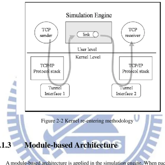
2.1.2 Kernel Re-entering Engine
EstiNet can use real-life TCP/IP protocol stack in OS kernel to generate high-fidelity simulation results by using “kernel re-entering” method which is exclusive to EstiNet. By applying “kernel re-entering”, EstiNet can always keep on the state-of-the-art TCP/IP version no matter whether the TCP/IP version changes or not.
Figure 2-2 shows the basic idea of “kernel re-entering”. Notice that the two TCP/IP protocol stacks in the figure map to the real TCP/IP protocol stack in Linux kernel, so actually they are the same. The tunnel interface is created by simulation engine to communicate with the kernel, issuing read/write system calls for
In the route that packets go from sender to receiver, packets will pass through the kernel two times via tunnel interface, that’s why we call this method “kernel
re-entering”.
Figure 2-2 Kernel re-entering methodology
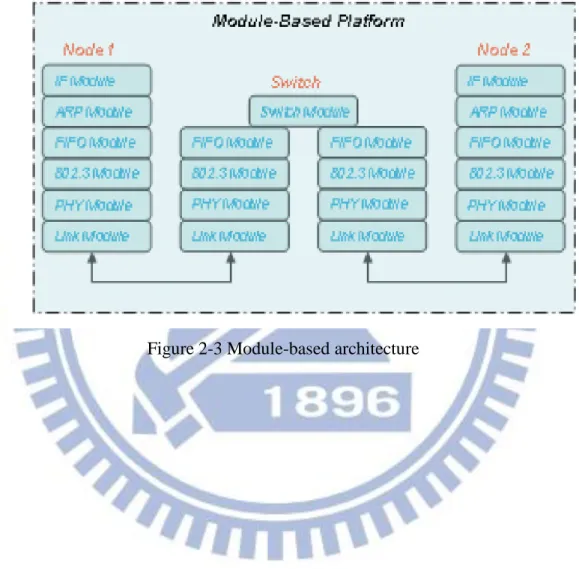
2.1.3 Module-based Architecture
A module-based architecture is applied in the simulation engine. When packets are retrieved into simulation engine from the kernel, all the simulation will be done in the specific module sequentially. Figure 2-3 shows the module-based architecture and figure 2-4 demonstrates the overview of simulation flow.
Simulation engine will trigger series of simulations corresponding to each
module. Besides, simulation engine only simulates packets behaviors lower than layer 3 in the OSI model, and the protocols upper than layer 3 always belongs to the
real-world OS’s and applications’ work as we see in figure 2-4.
6
type across the EstiNet. Everyone can create his own module following this framework. The communication between each module uses the member function send() and recv() of “NslObject”. Send() pushes packets into lower module, while recv() delivers packets to upper module. There is an example of communication between modules in figure 2-5.
Figure 2-4 Overview of simulation flow
8
2.2 LTE
LTE is 4G telecommunication technology which supports higher data transmission rate compared with 3G network. With MIMO (Multiple-Input and Multiple-Output) and OFDMA (Orthogonal Frequency-Division Multiple Access) technology breakthrough in physical layer, LTE improves both the transmission rate and bandwidth utilization.
2.2.1
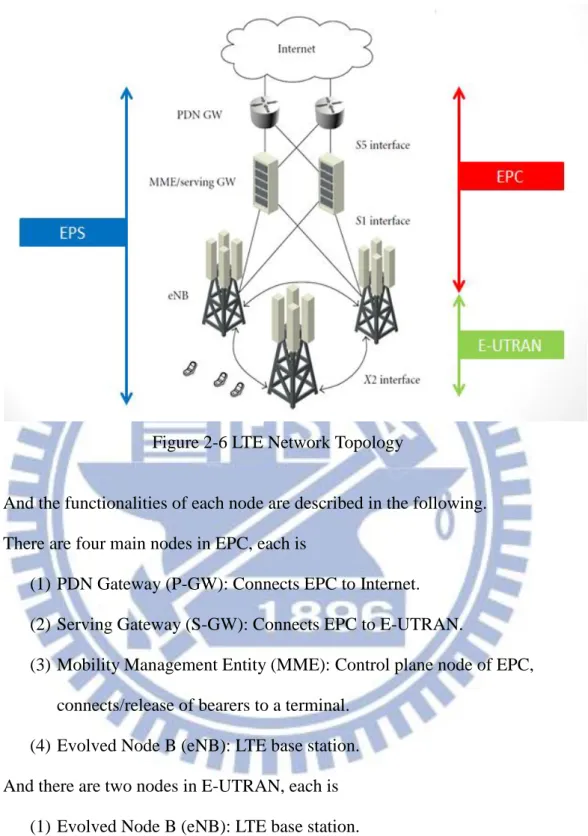
LTE Topology
There are many nodes to constitute a basic LTE network, which is called EPS (Evolved Packet System). EPS can be divided into two parts, EPC (Evolved Packet Core) and E-UTRAN (Evolved UMTS Terrestrial Radio Access Network). EPC handles cable network (Ethernet) while E-UTRAN is responsible to wireless part. The whole topology is shown in Figure 2-6.
Figure 2-6 LTE Network Topology
And the functionalities of each node are described in the following. There are four main nodes in EPC, each is
(1) PDN Gateway (P-GW): Connects EPC to Internet. (2) Serving Gateway (S-GW): Connects EPC to E-UTRAN.
(3) Mobility Management Entity (MME): Control plane node of EPC, connects/release of bearers to a terminal.
(4) Evolved Node B (eNB): LTE base station. And there are two nodes in E-UTRAN, each is
(1) Evolved Node B (eNB): LTE base station.
10
2.2.2
E-UTRAN Protocol Stacks and Channel
Mapping
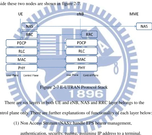
Next we are going to focus on the wireless part of LTE, E-UTRAN. We have mentioned that there are two nodes in E-UTRAN, eNB and UE. The protocol stacks inside these two nodes are shown in figure 2-7.
Figure 2-7 E-UTRAN Protocol Stack
There are six layers in both UE and eNB, NAS and RRC layer belongs to the control plane only. There are further explanations of functionality of each layer below:
(1) Non Access Stratum (NAS): handle EPS bearer management, authentication, security, paging, assigning IP address to a terminal. (2) Radio Resource Control (RRC): Handle RAN-related procedures, such
as broadcast message, setting up bearers, mobility, and measurement configuration.
(3) Packet Data Convergence Protocol (PDCP): Perform IP header compression and data ciphering.
retransmission handling, duplicate detection and in-sequence data delivery.
(5) Medium Access Control (MAC): Handle multiplexing of logical channels, HARQ retransmission and uplink/downlink scheduling. (6) Physical Layer (PHY): Handle coding/decoding, MIMO mapping,
modulation/demodulation.
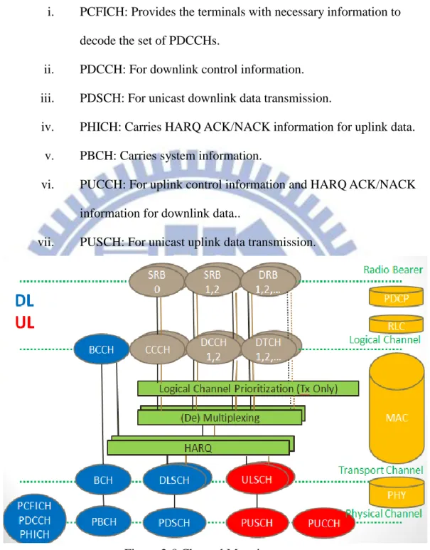
And channel mapping, figure 2-8 illustrates it.
(1) Radio Bearer: Connection between eNB and UE.
i. SRB0: Random Access Information.
ii. SRB1, 2: Control Information.
iii. DRB1, 2: Pure user data.
(2) Logical Channel: Defines the type of information it carries.
i. BCCH: For transmission of system information from the network
to all terminals in a cell.
ii. CCCH: For transmission of control information in conjunction with random access.
iii. DCCH: For transmission of control information to/from a terminal.
iv. DTCH: For transmission of user data to/from a terminal. (3) Transport Channel: Distinguishes different transport-block size,
modulation-and-coding scheme, and antenna mapping between each type of data.
i. BCH: For transmission of BCCH system information.
ii. DLSCH: For transmission of downlink data.
iii. ULSCH: For transmission of uplink data.
12
transmission of a particular transport channel.
i. PCFICH: Provides the terminals with necessary information to decode the set of PDCCHs.
ii. PDCCH: For downlink control information.
iii. PDSCH: For unicast downlink data transmission.
iv. PHICH: Carries HARQ ACK/NACK information for uplink data.
v. PBCH: Carries system information.
vi. PUCCH: For uplink control information and HARQ ACK/NACK
information for downlink data..
vii. PUSCH: For unicast uplink data transmission.
Figure 2-8 Channel Mapping
2.2.3
E-UTRAN Dataflow
In E-UTRAN, in the path that data was sent from transmitting side and received on receiving side, data pass all the layers in eNB and UE. Transmitting side fragments
and concatenates packets, and adds header, CRC, channel coding, etc., while
receiving side removes and checks all these additional information and reassemble the packets. Figure 2-9 to Figure 2-11 show the user-plane data block transition on
transmitting side.
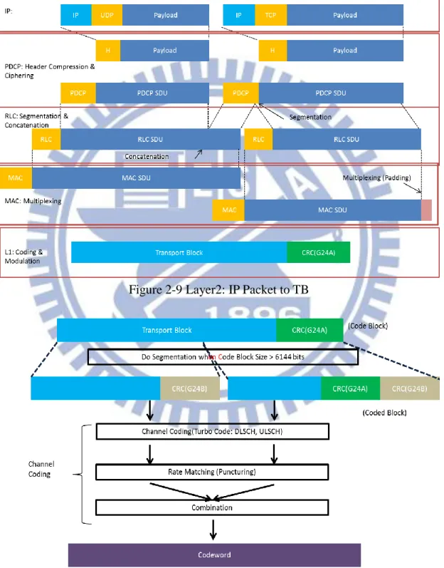
Figure 2-9 Layer2: IP Packet to TB
14
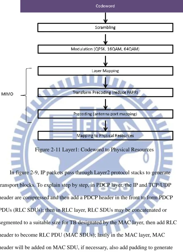
Figure 2-11 Layer1: Codeword to Physical Resources
In figure 2-9, IP packets pass through Layer2 protocol stacks to generate transport blocks. To explain step by step, in PDCP layer, the IP and TCP/UDP header are compressed and then add a PDCP header in the front to form PDCP PDUs (RLC SDUs); then in RLC layer, RLC SDUs may be concatenated or segmented to a suitable size for TB designated by the MAC layer, then add RLC header to become RLC PDU (MAC SDUs); lastly in the MAC layer, MAC header will be added on MAC SDU, if necessary, also add padding to generate Transport-Blocks. At this point, the work of data block transition in Layer2 is done. In figure 2-10, continuing with TB, layer1 first adds CRC24A to the TB, and we call it code block, then segments the code block if it is larger than 6144 bits, and adds CRC24B again. The purpose of segmentation is to fit the channel coding block size. Since we get suitable size code blocks, we can apply it with
channel coding to generate codewords. In figure 2-11, the codewords pass through scrambling, modulation, MIMO functions, and then are mapped on designated physical resources, ready to be transmitted.
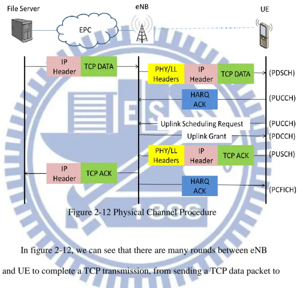
Another aspect of dataflow is the interaction between eNB and UE to complete a transmission, figure 2-12 shows the procedures.
Figure 2-12 Physical Channel Procedure
In figure 2-12, we can see that there are many rounds between eNB and UE to complete a TCP transmission, from sending a TCP data packet to receiving TCP ACK. After eNB receives data from the server, it adds PHY and link layer header to data and then transmits data to UE. When UE receives data, UE should respond HARQ ACK and an uplink scheduling request, then waits for uplink grant from eNB. Until receiving uplink grant, UE can send back TCP ACK, then eNB forward TCP ACK to the server, and also responds a HARQ ACK for TCP ACK to UE. A TCP data packet transmission is complete only when the above procedures are done by eNB
16 and UE.
2.2.4
HARQ
HARQ (hybrid-ARQ) is a technique combined with ARQ (Automatic
Repeat-reQuest) and FEC (Forward Error-Correction). Through ARQ, packets’ error can be detected, and those damaged packets may be recovered via FEC. HARQ provides more reliable data transmission.
In LTE, HARQ can be divided into two parts, HARQ entity and HARQ process, and HARQ entity maintains many HARQ processes. We will detail HARQ entity first and HARQ process second.
2.2.4.1
HARQ Entity
The unit which HARQ entity handles is TB, and HARQ entity will
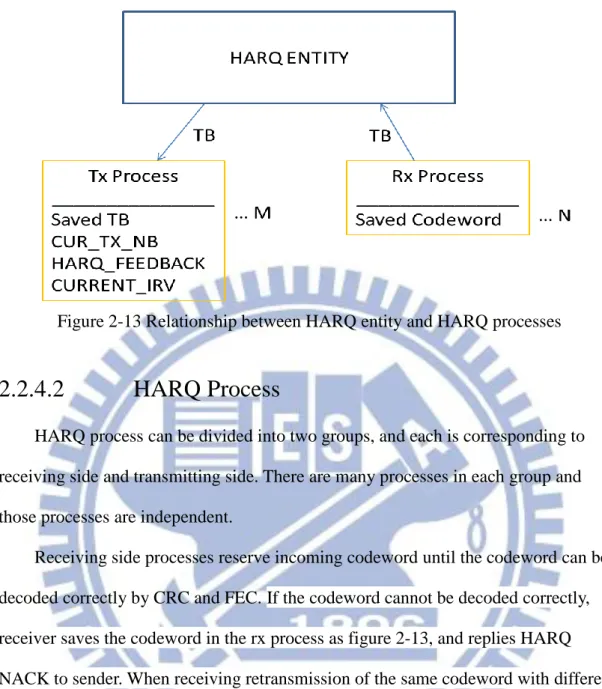
dispatch/receive TBs to/from HARQ processes. HARQ entity also directs HARQ information which contains TB size, HARQ process ID, NDI, RV, etc. to the corresponding HARQ process, then the designated HARQ process follows HARQ information to transmit/receive data. In other words, HARQ entity controls HARQ processes’ activities, and HARQ processes just execute on the commands. Figure 2-13 depicts the relationship between HARQ entity and HARQ processes.
Figure 2-13 Relationship between HARQ entity and HARQ processes
2.2.4.2
HARQ Process
HARQ process can be divided into two groups, and each is corresponding to receiving side and transmitting side. There are many processes in each group and those processes are independent.
Receiving side processes reserve incoming codeword until the codeword can be decoded correctly by CRC and FEC. If the codeword cannot be decoded correctly, receiver saves the codeword in the rx process as figure 2-13, and replies HARQ NACK to sender. When receiving retransmission of the same codeword with different RV, the previous incorrectly decoded codeword will be combined with the
retransmission codeword, generating a more robust codeword to be decoded again. Rx process will repeat the above procedures which include combining codeword,
decoding, replying HARQ NACK until decoding codeword correctly, then delivers the resulting TB to the upper layer and replies HARQ ACK to the sender.
On transmitting side, HARQ processes add CRC, FEC on TB to generate codeword, and then deliver the codeword to the next layer. After sending codeword, HARQ process waits for ACK/NACK reply, if it receives ACK, it discards the saved TB and get a new TB to transmit, otherwise, it retransmit the original TB with
18
different RV as figure 2-13, until receiving ACK or retransmission times exceeds retransmission threshold, and reports this situation to upper layer to handle this problem.
2.2.4.3
HARQ Process Number
HARQ Process Number is related to HARQ RTT,which depends on processing
time and DL/UL configuration. DL/UL configuration is shown is Table 2-1.
Processing time is approximately 3 ms, and HARQ RTT is calculated by the longest time interval between two transmissions on the same HARQ process.
Take TDD DL/UL configuration 0 and FDD for example separately. Figure 2-14 demonstrates different situations on HARQ RTT. For FDD, HARQ RTT is constantly 8 ms. At 1st ms eNB sends downlink data and meanwhile UE receives the data within 1 ms, after 3 ms processing, UE sends HARQ ACK at 5th ms, then eNB receives
HARQ ACK and then waits 3 ms processing time to decode. Until 9th ms eNB can know the decode results then decide to do retransmission or send the next TB by the same HARQ process. From 1st ms to 9th ms, there are 8 blanks in this period without any downlink transmission, so we need 8 HARQ processes to fill the blanks for both downlink and uplink on UE and eNB, and it will be the same situation on uplink. For TDD DL/UL configuration 0, although HARQ RTT varies, the longest HARQ RTT is 11 ms. In different situations UE sends uplink data at 1st and 2nd ms, and eNB should sends back HARQ ACK at 5th and 6th ms respectively, however 5th and 6th time slot
both belong to UL, so in both situation, eNB can only send back HARQ ACK at 8th ms, resulting in that the next time for issuing an uplink transmission on the same HARQ process is at 12th ms. Here we see the reason why the RTT varies. Then we take the longest HARQ RTT as our base to assign TX/RX HARQ process number. From 1st to 12thms, there are 7 uplink slots and 4 downlink slots. In UE, the number of
TX HARQ PROCESS is 7, number of RX HARQ PROCESS is 4, and for eNB, it is just the opposite on UE.
Uplink-downlink configuration Downlink-to-Uplink Switch-point periodicity Subframe number 0 1 2 3 4 5 6 7 8 9 0 5 ms D S U U U D S U U U 1 5 ms D S U U D D S U U D 2 5 ms D S U D D D S U D D 3 10 ms D S U U U D D D D D 4 10 ms D S U U D D D D D D 5 10 ms D S U D D D D D D D 6 5 ms D S U U U D S U U D
Table 2-1 TDD DL/UL configuration
Figure 2-14 HARQ RTT
TX HARQ PROCESS use stop-and-wait mechanism, each TX HARQ PROCESS is independent. The TX HARQ PROCESS which completes its
transmission first will retrieve the next TB in DLSCH. We make an example in Table 2-2, supposing using FDD, so there are 8 TX HARQ PROCESS and HARQ RTT is 8 ms. In table 2-2, the left column is the situation of tx process, showing that a TB Y is sent by a tx process #P N times. On the contrary, right column is the situation of rx process, showing that a TB Y is received by rx process #P, and D is decode results.
20
Notice that tx process #0 and #3 both failed at the first transmission in TTI #0 and TTI #3, respectively, so the both tx process should issue a retransmission after a HARQ RTT, until TTI #9 and TTI #11, respectively. At this time, tx process #0 and #3 both have a successful retransmission, so they can get a new TB for next transmission after a HARQ RTT to TTI#17 and TTI#19.
Tx (P, Y, N) TTI # Rx (P, Y, D) P(0, TB1, 1stsend) 0 P(0, TB1, fail) P(1, TB2, 1stsend) 1 P(1, TB2, success) P(2, TB3, 1stsend) 2 P(2, TB3, success) P(3, TB4, 2ndsend) 3 P(3, TB4, fail) P(4, TB5, 1stsend) 4 P(4, TB5, success) P(5, TB6, 1stsend) 5 P(5, TB6, success) P(6, TB7, 3rdsend) 6 P(6, TB7, success) P(7, TB8, 1stsend) 7 P(7, TB8, success) P(0, TB1, 1stsend) 8 P(0, TB1, success) P(1, TB9, 2ndsend) 9 P(1, TB9, success) P(2, TB10, 1stsend) 10 P(2, TB10, success) P(3, TB4, 2ndsend) 11 P(3, TB4,success) P(4, TB11, 1stsend) 12 P(4, TB11, success) … … …
3. Related Work
Being a state-of-art technology, there are varieties of researches in LTE field which is spread from the application layer to the physical layer. All of those researches aim to increasing throughput or decreasing packet error rate.
In physical layer, we can classify research fields into four categories. First is the improvement on MIMO and modulation technique. Second issue belongs to channel coding methodology. Third issue is RBs scheduling, which achieves higher utilization on time-frequency domain RBs. The third issue is the popular issue recently in
physical layer. The fourth issue is relatively smaller, saving control channel overhead to increase user data space.
In link layer which includes from PDCP layer to MAC layer, research issues can be divided into three categories. First one is about QoS,. which emphasizes on logical channel prioritization Second one is related to interaction between ARQ and HARQ, which reduces the overall packet loss rate in E-UTRAN. Third topic uses TTI
bundling to improve VoIP quality. All the discussions in link layer are almost involved in quality of data transmission and VoIP.
All of the above issues plus handover problem are mainly related to Layer1 and Layer2, and then we are going to look on TCP performance in whole system
separately.
In network layer, RTT is one of main factors which impacts TCP throughput. By the equation “throughput <= windowSize/rtt”, we know that smaller RTT results in higher throughput. There are many papers such as [10][11][12] focusing on how to minimize RTT by reduction of control channel time consumption. And we highly base
22 on [10] to do further research.
A scheme is proposed in [10] in which eNB generates a fake TCP ACK stored in eNB, applies a hash value to the fake TCP ACK. Then in UE side, UE integrates TCP ACK Index(hash value) into HARQ ACK, and sends both HARQ ACK and TCP ACK Index in the original HARQ ACK. When HARQ ACK is received by eNB, the TCP ACK Index will invoke eNB to retrieve the stored fake TCP ACK by hash value, and then send back the fake TCP ACK to Server. Thus reducing the control channel handshaking time in overall TCP RTT, and making progress on TCP throughput performance. Figure 3-1 shows the scenario.
4. Design and Implementation
4.1 New Design Architecture
Based on [10], in the same point of view, we proposed a new architecture that not only reduces control channel handshaking time but also reduces HARQ RTT. In the new architecture, eNB returns TCP ACK immediately to Server, no longer waiting the HARQ ACK sent by UE, and thus reducing HARQ RTT. In other words, we break one TCP data loop into two parts, Server-eNB and eNB-UE.
However, there is a drawback of this method. Under a circumstance that two loops are not balanced on throughput, usually Server-eNB loop overwhelms eNB-UE loop, the incoming data will accumulate rapidly and then overflow in eNB. To avoid this problem, we add FakeAckQ and DataQ-Threshold into our mechanism. If the accumulative data exceeds the DataQ-Threshold, the fake TCP ACK will be pushed into FakeAckQ instead of being sent back to the server immediately. When the accumulative data is lower than DataQ-Threshold, eNB restarts sending fake TCP ACK in FakeAckQ to the server. Via this controlling mechanism, we can balance the two data loops to avoid data overflow. Figure 4-1 and Figure 4-2 show the design of this method.
24
Figure 4-1 Proposed Architecture
Figure 4-2 Implementation topology
4.2 Implementation
4.2.1
HARQ Implementation
In HARQ implementation, we follow figure 4-3 and figure 4-4 to implement. Figure 4-3 shows Tx side activity, and figure 4-4 shows Rx side activity.
Figure 4-3 HARQ implementation flowchart at Tx Side
26
At Tx Side, first HARQ ENTITY computes tx process id and then check whether it is in retx state or not. If the tx process is in retx state, that means there is already a codeword to retransmit, else HARQ ENTITY puts a new TB into the tx process then generates a new codeword. Last step before sending the codeword is adding
transmission times on that codeword, for knowing whether the transmission time exceeds retransmission threshold or not. When receiving HARQ ACK/NACK, HARQ ENTITY verifies which tx process should correspond to the feedback. If it receives HARQ ACK, then it resets the assigned tx process’s data. If instead it receives HARQ NACK, it checks whether the transmission times exceed retransmission threshold or not. If transmission times exceed the threshold, it reschedules the codeword in RLC layer. If not, it remains the codeword and then waits for the next retransmission.
At Rx Side, after receiving a codeword, HARQ ENTITY computes a
corresponding rx process to handle the codeword, and then decodes the codeword. If the codeword is decoded correctly, it resets the rx process’s data, and then reports HARQ ACK. If not, it remains the codeword in the rx process for combining the codeword with the next receiving codeword on the same rx process.
4.2.2
Generate Fake TCP ACK
Since we need to make fake TCP ACK, we forge the fake TCP ACK as figure 4-5 shows. Those red words are what we should change TCP/IP header. We need retrieve some information from the original TCP DATA PACKET, and the information contains Source IP address, Destination IP address, Source Port, Destination Port,
Sequence Number, and Acknowledgment Number. The time we retrieve the
information is that when TCP DATA PACKET comes into RRC module in eNB. And we should fill IHL, Total length, Data Offset, and Window fields by our own, but ignore checksum in the simulation environment. Most importantly, we set ACK field
to 1 to indicate that the packet is a TCP ACK PACKET.
Figure 4-5 Generating Fake TCP ACK Packet
4.2.3
DataQ-AckQ control mechanism
We have mentioned that there should have a DataQ-AckQ control mechanism to avoid data overflow caused by the two unbalanced data loops in new architecture, and figure 4-6 displays the pseudo code of the control mechanism.
Notice that the “current FakeAck” is only transmitted when the accumulative
data is less than threshold and FakeAckQ is empty after trying to transmit FakeAck in
FakeAckQ, and that if both the condition are not met, the “current FakeAck” will be pushed into FakeAckQ. When transmitting FakeAck from FakeAckQ, we confine the transmitting packets no more than 10 in consecutive, otherwise, ACK burst will harm TCP performance.
28
5. Performance Evaluation
5.1 Simulation Environment
We set simulation environment as figure 5-1. The modulation is QPSK such that the maximum throughput on wireless part is 32Mbit/s and we choose FDD as
communication type which the HARQ RTT is always 8 ms and both TX and RX HARQ PROCESS number is 8. Other parameters like one way link delay between eNB and Server, block error rate (BER) are also shown in figure 5-1. The DataQ capacity is set to 200KB to meet forged TCP window size. AckQ capacity is
boundless, and DataQ-threshold is set to 100KB. Traffic flow is generated by running stg/stcp on server and running rtg/rtcp on UE, and we only simulate downlink
transmission.
30
5.2 Case1 – Greedy TCP
In this case, dataQ-threshold is set to 100KB, fakeAck’s window size is set to 195,200 bytes, and this simulation will last 30s. Figure 5-2 to figure 5-9 show the comparison of “Normal ACK” and the proposed “Fake ACK”’s performance by using delay time as the parameter of x-axis. We can find that when link delay is greater than 20 ms, “Fake ACK” is better than “Normal ACK”, and as link delay continues
climbing up, the differences between “Fake ACK” and “Normal ACK” is getting closer. Thus, we can see that “Fake ACK” does benefit the performance by reduction of RTT, but in high link delay environment, the reduction of HARQ RTT only has less impact compared to the higher link delay.
Figure 5-2 Case1 Result: Link Delay 5 ms 0 5 10 15 20 25 30 35 Throughput (Mbit/s) BER
Link Delay 5 ms
Normal ACK Fake ACKFigure 5-3 Case1 Result: Link Delay 10 ms
Figure 5-4 Case1 Result: Link Delay 15 ms 0 5 10 15 20 25 30 35 Throughput (Mbit/s) BER
Link Delay 10 ms
Normal ACK Fake ACK 0 5 10 15 20 25 30 Throughput (Mbit/s) BERLink Delay 15 ms
Normal ACK Fake ACK32
Figure 5-5 Case1 Result: Link Delay 20 ms
Figure 5-6 Case1 Result: Link Delay 25 ms 0 5 10 15 20 25 30 Throughput (Mbit/s) BER
Link Delay 20 ms
Normal ACK Fake ACK 0 5 10 15 20 25 Throughput (Mbit/s) BERLink Delay 25 ms
Normal ACK Fake ACKFigure 5-7 Case1 Result: Link Delay 30 ms
Figure 5-8 Case1 Result: Link Delay 50 ms 0 2 4 6 8 10 12 14 16 18 Throughput (Mbit/s) BER
Link Delay 30 ms
Normal ACK Fake ACK 0 2 4 6 8 10 12 Throughput (Mbit/s) BERLink Delay 50 ms
Normal ACK Fake ACK34
Figure 5-9 Case1 Result: Link Delay 100 ms
Another aspect of this experiment is to set parameter of x-axis to delay time as in Figure 5-10 to figure 5-15. In “BER = 1/10^2”, we see that “Fake ACK” looks much better than “Normal ACK”, it’s because that when TCP needs to issue a
retransmission, “Fake ACK” can eliminate link delay in EPC for retransmission. But when link delay goes to large, the circumstance is difficult for both “Fake ACK” and “Normal ACK”, so they have an intersection at 100 ms of x-axis.
Figure 5-10 Case1 Result: BER 0 0 1 2 3 4 5 6 Throughput (Mbit/s) BER
Link Delay 100 ms
Normal ACK Fake ACK 0 5 10 15 20 25 30 35 5 10 15 20 25 30 50 100 Throughput (Mbit/s) Delay Time (ms)BER = 0
Normal ACK Fake ACKFigure 5-11 Case1 Result: BER 1/10^6
Figure 5-12 Case1 Result: BER 1/10^5 0 5 10 15 20 25 30 35 5 10 15 20 25 30 50 100 Throughput (Mbit/s) Delay Time (ms)
BER = 1/10^6
Normal ACK Fake ACK 0 5 10 15 20 25 30 35 5 10 15 20 25 30 50 100 Throughput (Mbit/s) Delay Time (ms)BER = 1/10^5
Normal ACK Fake ACK36
Figure 5-13 Case1 Result: BER 1/10^4
Figure 5-14 Case1 Result: BER 1/10^3 0 5 10 15 20 25 30 35 5 10 15 20 25 30 50 100 Throughput (Mbit/s) Delay Time (ms)
BER = 1/10^4
Normal ACK Fake ACK 0 5 10 15 20 25 30 5 10 15 20 25 30 50 100 Throughput (Mbit/s) Delay Time (ms)BER = 1/10^3
Normal ACK Fake ACKFigure 5-15 Case1 Result: BER 1/10^2
From the above observation, here pops up a problem, why doesn’t “Fake ACK” performance get better than “Normal ACK” in low latency and low BER environment? Figure 5-16 to Figure 5-19 explain it. We observe that all the statistics varies by a constant period. First looking at DataQ and AckQ, DataQ length is almost around 80KB to 120KB by the effect of threshold, and while DataQ length exceeds the threshold, AckQ will start to accumulate FakeAcks. Next focusing on “Window Size” and “RTT”, “Window Size” will reduce to 1 every period of time whenever “RTT” burst at the same period of time. That’s because that FakeAck is queued in AckQ as the queue length becomes larger, and the larger queue length results in the larger RTT since the AckQ is FIFO as in figure 5-19. Because the FakeAck can’t be received by server in time and the burst RTT is 10 more times than usual, timeout happens on server and TCP window size is reduced by its congestion control protocol to 1. The upper part in figure 5-18 is calculated by formula “throughput = windowSize/rtt” time by time, we can see that throughput also varies in period, and if we compute the average on both window size and rtt, the results will be 22.6 ms and 65,129 bytes, respectively. If we use the average window size to divide the average RTT, we will get
0 2 4 6 8 10 5 10 15 20 25 30 50 100 Throughput (Mbit/s) Delay Time (ms)
BER = 1/10^2
Normal ACK Fake ACK38
a throughput of 23.1 Mbit/s, which is lower than the wireless bandwidth. So the above activities between AckQ, DataQ, RTT, and Window Size are the reason why
“FakeAck”’s performance can’t achieve wireless bandwidth in low latency and low BER environment.
Figure 5-17 Case1 Explanation: DataQ and AckQ
40
Figure 5-19 Case1 Explanation: RTT and AckQ Overlapping
5.3 Case2 – Small Webpage Download
Another benefit of the proposed architecture is decreasing small webpage download time. By sending FakeAck, we can reduce RTT between server and UE perceived by server to decrease webpage download time. Figure 5-20 to figure 5-31 show that “Fake ACK” spends less download time than “Normal ACK” from 5 ms to 100 ms EPC link delay in 40KB to 100KB webpage size. In figure 5-20 to 5-27, first we can perceive the larger webpage, the longer webpage download time. Second, we can find that the higher latency in EPC, the lower improvement of “Fake ACK”. It’s because that as latency in EPC grows higher, the reduced 8 ms HARQ RTT stands a lower percentage to the total RTT, and thus HARQ RTT has smaller impact on the overall performance. Figure 5-28 to figure 5-31 show that the download time as delay time varies in the same webpage size, this tells the impact of delay time.
Figure 5-20 Case2 Result: Link Delay 5 ms
Figure 5-21 Case2 Result: Link Delay 10 ms 0 20 40 60 80 100 120 100 80 60 40 Consuming time (ms)
Web Page Size (KB)
Link Delay 5 ms
Normal ACK Fake ACK 0 20 40 60 80 100 120 140 160 180 100 80 60 40 Consuming time (ms)Web Page Size (KB)
Link Delay 10 ms
Normal ACK Fake ACK
42
Figure 5-22 Case2 Result: Link Delay 15 ms
Figure 5-23 Case2 Result: Link Delay 20 ms 0 50 100 150 200 250 100 80 60 40 Consuming time (ms)
Web Page Size (KB)
Link Delay 15 ms
Normal ACK Fake ACK 0 50 100 150 200 250 300 100 80 60 40 Consuming time (ms)Web Page Size (KB)
Link Delay 20 ms
Normal ACK Fake ACK
Figure 5-24 Case2 Result: Link Delay 25 ms
Figure 5-25 Case2 Result: Link Delay 30 ms 0 50 100 150 200 250 300 350 100 80 60 40 Consuming time (ms)
Web Page Size (KB)
Link Delay 25 ms
Normal ACK Fake ACK 0 50 100 150 200 250 300 350 400 100 80 60 40 Consuming time (ms)Web Page Size (KB)
Link Delay 30 ms
Normal ACK Fake ACK
44
Figure 5-26 Case2 Result: Link Delay 50 ms
Figure 5-27 Case2 Result: Link Delay 100 ms 0 100 200 300 400 500 600 700 100 80 60 40 Consuming time (ms)
Web Page Size (KB)
Link Delay 50 ms
Normal ACK Fake ACK 0 200 400 600 800 1000 1200 1400 100 80 60 40 Consuming time (ms)Web Page Size (KB)
Link Delay 100 ms
Normal ACK Fake ACK
Figure 5-28 Case2 Result: Webpage Size 100KB
Figure 5-29 Case2 Result: Webpage Size 80KB 0 200 400 600 800 1000 1200 1400 5 10 15 20 25 30 50 100 Consuming time (ms) Delay Time (ms)
Web Page Size 100KB
Normal ACK Fake ACK 0 100 200 300 400 500 600 700 800 900 1000 5 10 15 20 25 30 50 100 Consuming time (ms) Delay Time (ms)
Web Page Size 80KB
Normal ACK Fake ACK
46
Figure 5-30 Case2 Result: Webpage Size 60KB
Figure 5-31 Case2 Result: Webpage Size 40KB 0 100 200 300 400 500 600 700 800 900 1000 5 10 15 20 25 30 50 100 Consuming time (ms) Delay Time (ms)
Web Page Size 60KB
Normal ACK Fake ACK 0 100 200 300 400 500 600 700 800 5 10 15 20 25 30 50 100 Consuming time (ms) Delay Time (ms)
Web Page Size 40KB
Normal ACK Fake ACK
5.4 Case3 – Saving UL Bandwidth
Since we have dropped TCP ACK generated by UE, this behavior can also save UL bandwidth. Applying QPSK in modulation, the maximum throughput is
approximately 32Mbit/s, and we suppose a TCP DATA packet is 1500 bytes, so there
should be ((32 ∗ 1000000)/8)/1500 = 2,667 packets per second. And each TCP
ACK occupies 40bytes at least, so UE may save uplink bandwidth with 2667 * 40 = 106,680 bytes per second, approximately to 100KB per second.
48
6. Conclusion
In this thesis, we introduce LTE topology and HARQ sequentially, and then search related paper of reducing RTT to increase throughput. Lastly, we proposed a new architecture based on the idea.
This proposed architecture is applied in DL network and the improvement decreases while EPC link delay increases. However, because in low EPC link delay environment, data throughput can’t reach wireless bandwidth, and the DataQ and AckQ length consumes memory in eNB, there are some constraints to this
architecture.
Despite the constraints, we still can take advantage on this architecture in a suitable range of link delay and low BER environment or for small webpage downloading, and it is confirmed that RTT still plays an important role in any TCP throughput.
7. Future Work
This architecture is without experiments on mobility network. It will surely be more complex on mobile conditions because if server data are already preserved in eNB, when UE moves to another eNB, how should the data be transferred? We also have to consider the trade-offs in such a complex environment. This part is left as future work.
50
8. Reference
[1] 3GPP TS 36.300 V10.4.0, Evolved Universal Terrestrial Radio Access (E-UTRA) and Evolved Universal Terrestrial Radio Access Network (E-UTRAN); Overall description; Stage 2.
[2] 3GPP TS 36.331 V10.0.0, Evolved Universal Terrestrial Radio Access (E-UTRA); Radio Resource Control (RRC); Protocol specification.
[3] 3GPP TS 36.321 V10.0.0, Evolved Universal Terrestrial Radio Access (E-UTRA); Medium Access Control (MAC) protocol specification.
[4] 3GPP TS 36.322 V10.0.0, Evolved Universal Terrestrial Radio Access (E-UTRA); Radio Link Control (RLC) protocol specification.
[5] 3GPP TS 36.323 V10.1.0, Evolved Universal Terrestrial Radio Access (E-UTRA); Packet Data Convergence Protocol (PDCP) specification.
[6] 3GPP TS 36.211 V10.0.0, Evolved Universal Terrestrial Radio Access (E-UTRA); Physical channels and modulation.
[7] 3GPP TS 36.212 V10.0.0, Evolved Universal Terrestrial Radio Access (E-UTRA); Multiplexing and channel coding.
[8] 3GPP TS 36.213 V10.0.1, Evolved Universal Terrestrial Radio Access (E-UTRA); Physical layer procedures.
[9] Anna Larmo, Magnus Lindström, Michael Meyer, Ghyslain Pelletier, Johan Torsner, and Henning Wiemann, Ericsson Research, “The Link Layer Design”, IEEE Communications Magazine • April 2009
[10] Dzmitry Kliazovich and Fabrizio Granelli, Simone Redana and Nicola Riato, “Cross-Layer Error Control Optimization in 3G LTE”, Global Telecommunications
Conference, 2007. GLOBECOM ’07 IEEE
[11] Dongmyoung Kim, Sch. of Electr. Eng. & INMC, Seoul Nat. Univ., Seoul;
Youngkyu Choi,Sunggeun Jin;Kwanghun Han; Sunghyun Choi, “A MAC/PHY
Cross-Layer Design for Efficient ARQ Protocols”, Communications Letters, IEEE [12] Hyun-Seo Park, Internet Future Technol. Res. Dept., ETRI, Daejeon, South Korea, Jae-Yong Lee; Byung-Chul Kim, “TCP performance issues in LTE networks”, ICT Convergence (ICTC), 2011 International Conference.