Design and Implementation of 2.4GHz Wireless Skype Phone
5
0
0
全文
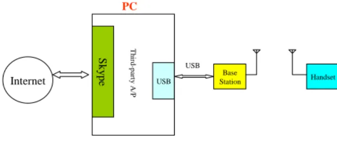
(2) Additionally, the system we proposed is also designed with a specific sleep mode to reduce the power consumption. From the physical power measurement result, our system consumes less power than the Bluetooth earphones in the market by 13%. The rest of the paper is organized as follows. In the next section, we provide an overview of our system architecture and the working principles. We also discuss some design issues such as connection mechanism between the base station and the handset. Section 3, 4, 5 describe the details of the system design. Section 6 presents the integrated system, the analysis of system performance and energy consumption. Finally, in section 7 we conclude our work and enumerate future avenues of research.. 2: System Architecture This section covers the overview of the proposed system architecture. We divide the system into two parts, the base station and the handset with three components – PC Client software, hardware and micro-controller. PC. shows the PCM implementation in our system. In the system we use 8KHz sampling rate because of the general speech frequency is ranging from 300 to 3.4KHz.. 110110101. Audio Input. Low Pass Filter. Sampling. Quantization. Third-party A/P. Skype. USB USB. Base Station. Handset. FSK Modulation. Fig. 2. PCM block diagram.. 2.2 FSK Modulation FSK modulation (Frequency Shift Key) is a method of transmitting digital signals and commonly believed to perform better in the presence of interfering signal. Two different carrier frequencies are used to represent zero and one. The logic 0 is represented by a wave at a specific frequency ωC − ωD , and logic 1 is represented by a wave at a different frequency ωC + ωD . The full equation is as following: VFSK (t ) = A cos(ωC ± ωD )t. Internet. PCM Coding. (1). where ωC is the carrier frequency and ωD is the value of carrier frequency offset. The value of A is the amplitude of FSK signal.. 2.3 Butterworth Low Pass Filter Fig. 1. The proposed system architecture. Fig. 1 shows the proposed block diagram of the different components in our Skype Phone. When the speech data is received from Internet, the Skype software transfers the data to the USB driver. The third-party application transfers the interface control parameters between the USB device and Skype by the USB HID driver. Then, PC transmits the speech data to the basestation and converts to digital data. The baseband circuit manages the speech in/out, including signal amplifier and low pass filter. The MCU converts the speech data by the ADC/DAC, enables the RF transceiver, and controls the system. In our system we employ pulse code modulation (PCM) and FSK modulation to digitize and code the voice signal for wireless communication.. 2.1 PCM In modern communication system, pulse code modulation is used comprehensively in today’s digital signal. It is a process in which analog signals are converted to digital form. The practical design of PCM always uses filtering, sampling, quantizing, and encoding to realize the physical implementation. Fig. 2. Low-pass filter in our system will pass relatively low frequency portions of the signal but filter out the high frequency ones. The Butterworth Filter we used is the filter type that results in the flattest pass band and contains a moderate group delay... 3: PC Client Software Design Most of VoIP applications either software or hardware phones need to work with the PC presently. In our system the PC client software is composed of Skype API, USB audio driver, and third-party application. Skype is a pure VoIP application that we need a third party application to transfer message between Skype and device. Fig. 3 shows the relationship between each layer and component. In the proposed system the third party application use USB interrupt to transfer state messages and control device polling signals. The Skype API is divided into two separate parts: Skype Phone API and Skype Access API. Skype Phone API is an interface that Skype uses to access devices. This API is controlled by Skype and the device-side of the API can be viewed as a driver. Skype Access API is an interface that Skype publishes to third party applications to access Skype functionality. The USB Driver which plays an important role in our. - 46 -.
(3) system includes control transfer, interrupt transfer, isochronous transfer, and bulk transfer. We use the isochronous transfer in voice data transmission and the interrupt transfer in volume and function control. Besides, since we use the USB interface to transfer voice and control the volume, we need to support HID Device Class and Audio Device Class [13][14]. Third Party Application. USB HID Driver Interrupt. perform wireless, digital, full-duplex speech compression and decompression function [11]. To design an efficient transmission in the 2.4GHz wireless band and avoid the interference are a challenge work. Therefore, we selected Nordic nRF2401 [8] as 2.4GHz RF transceiver so as to achieve small-size, low cost, low current consumption and low voltage. The output power and frequency channels of the transceiver are easily programmable and the current consumption is very low, Skype Phone API there is only 10.5mA at an output power of -5dBm and Application Layer Skype 18mA in receive mode. Application CM109 [5] is a highly integrated single chip USB Skype Access API audio controller for embedded earphone driver, booster, USB transceiver and specifically for VoIP application. It Driver Layer USB Audio is developed to enable a regular phone, handset, or Driver headset which is interfaced to the USB port on the PC. Fig. 4 illustrates the integrated architecture of the Isochronous basestation and the handset. As the Figure shows, we use the CM109 USB audio controller to be the interface USBD Driver between the PC and the base station.. 5: MCU Firmware Design. Fig. 3. System architecture of PC client software. Including the base station and the handset, the MCU design plays an important role in our system and the firmware is even more the core of the system design. In the Fig. 4 the MCU part is framed by a dotted line and we can easily find out the position in the whole system. The MCU controls the data transmission, enables the RF transceiver, ADC/DAC, and the communication with the PC and the handset.. .. Speaker. ADC. LPF. Encode. USB CM109. PC. Mic. RF Transceiver. 8051. 74595. DAC. LPF. Decode 1ms. C8051F330. USB. S O F. ISO_IN. ISO_OUT. S O F. ISO_IN. ISO_OUT. S O F. ISO_IN. 2ms. (a) System architecture of the basestation.. 1ms. Base Station. BS Send. ISO_OUT. S O F. ISO_IN. ISO_OUT. Next Freq Resend 1st. BS Send. BS Send. 300us. Handset Mic. Amp. ADC. Speaker. LPF. RF Transceiver. 8051. DAC. HS Send. 625us. Encode. Bluetooth Keypad. HS Send. Bluetooth interference. Fig. 5. The communication protocol of the proposed system.. Decode. C8051F330. (b) System architecture of the handset Fig. 4 System Architecture of basestation and handset. 4: Hardware Design The system hardware design is composed of baseband circuit, RF circuit and MCU circuit. The speech coprocessor used here is a low-power, small size and high levels of integration (on-chip ADC, DAC and 25 MIPS peak CPU) 8051 micro-controller [10]. It can. Most of wireless communication systems operate in half-duplex mode to avoid interference between transmitter and receiver. In our system the base station is the host and the handset is the terminal. The base station can send data on the line and then immediately receive data on the line from the same direction in which data was just transmitted. The communication protocol is shown in Fig. 5. We design the hopping mode like Bluetooth with 80 different channels. Considering the RF transfer/receive switch time 130us, we set the rate at 500 hopping per second. In order to transfer data correctly, synchronizing the handset to the basestation is crucial to the hopping system. This system exploits a parameter called TimeSlotCnt to count. - 47 -.
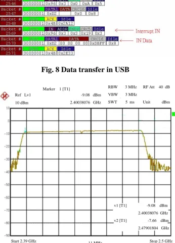
(4) time in both sides. When the data is transmitted, the TimeSlotCnt of the basestation is used to synchronize the hopping counter in the handset. We also design a data retransmission function in the proposed system for the speech performance. For the example in Fig. 5, when the data transmission is interfered with Bluetooth signal in 2.4GHz, the handset will not receive the message from the basestation. After 1ms, if the basestation still do not receive the acknowledge message from the handset, then the basestation will transmit the data again. When the data loss exceeds 2ms, the basestation and the handset will hop to the next frequency and try again. Furthermore, considering the tight power consumption of the handset we design the power saving mode. When the user presses the OFF button, the micro-controller switches off all the external current and then enters into sleep mode. The micro-controller wakes up periodically by the external RC charging and detects any button that has been pressed. Then the micro-controller sets the RF transceiver into receive mode in order to synchronize with the basestation. At last, the micro-controller examines the control field of received data and decides the next state. The complete state figure is shown in Fig. 6.. earphone. From the results, our system works in 27.34mA and the Bluetooth works in 31.41mA that we achieve about 13% energy saving. In the Fig. 8, we use the USB analyzer to acquire the data transferred in the USB bus. It shows that the third party application successfully uses the Set_Report command in the HID Device Class for transferring data.. C8051F330 MCU. RF transceiver. CM109 USB audio controller. Connect to the PC. (a) Basestation Power On. Current source for test. C8051F330 MCU MIC. Initial. Earphone Sleep Mode. Wakeup. Battery. [OFF] Receiver Mode. RF transceiver. Received data. Time Slot End Time Slot Timeout. Get Hopping Channel. ON/OFF button Transmit Mode. Keypad. Transmit data end. (b) Handset. Fig. 6. The state graph of the handset. 6: Integrated Performance. System. Outlook. Fig.7 System prototype. and. 7: Conclusion. The photograph of overall system prototype is shown in Fig. 7. The figure illustrated the outlook of the hardware structure of the basestation and the handset. The power consumption of the handset is measured by the NI DAQ (Data Acquisition) system. We placed a 10 ohm resistor in series with the test current source of the handset and sample the voltage drop across the resistor at 1000 samples/second. Then the NI Labview [16], a GUI-based data acquisition, measurement analysis, and presentation software processes the data and shows the computed current value dynamically on the screen. We also compare our result with a Bluetooth. We proposed a new style wireless 2.4GHz Skype phone to enhance the extremely limited range of USB internet phones. This system is implemented by using hopping technology, specific USB audio controller and RF transceiver. The 8051 microcontrollers are adopted as the coprocessor of the proposed system and control the client-server architecture to lower cost than Bluetooth. Unlike Bluetooth earphones the system is designed with a keypad that we can dial out by the handset device. The performance of the whole system is demonstrated. It is shown that the proposed design can produced good. - 48 -.
(5) quality with anti-interference characteristics. Furthermore, the work range is convenient enough to most of users. By means of the client-server architecture and the wireless operation feature this system can be used to derive many applications especially for convenience and mobility. In the future, we will focus on reducing the power consumption of the system and increasing the work range.. Fig. 8 Data transfer in USB RBW. 3 MHz. -9.08 dBm. VBW. 3 MHz. 2.40038076 GHz. SWT. 5 ms. Marker 1 [T1] Ref Lv1 10 dBm. v1 [T1]. RF Att. 40 dB. Unit. dBm. [4] Ruei-Xi Chen, Liang-Gee Chen, Mei-Juan Chen, and Tsung-Han Tsai, “An I-Phone System Design and Implementation with a Portable Speech Coding Coprocessor,” IEEE Transaction on Consumer Electronics, Vol. 43, No.4, pp.1262-1269, November 1997. [5] CM109 Datasheet, “CM109 USB Audio I/O Controller,” C-Media Electronics Inc, 2003. [6] S. Kaplan and J. R. Davies, “Micro-controller based Internet Phone,” Proceedings of the IEEE Africon 2004 on Digital Object Identifier, Gaborone, Botswana, , Vol.1, pp. 307-311, 15-17 September2004 [7] Bernard Sklar, “Digital Communications, Prentice Hall,” 1988. [8] Nrf24L01 Datasheet, “Single Chip 2.4GHz 2.4GHz Transceiver,” Nordic, 2005. [9] Skype, http://www.skype.com. [10] C8051F330 Datasheet, “Mixed Signal ISP Flash MCU,” Silicon Laboratories, 2005. [11] AN147 Reference Design, “Wireless Digital Full-Duplex Voice Transceiver”, Silicon Laboratories, 2005. [12] Jiang Li, Keman Yu, Gang Chen, Yong Wang, Hanning Zhou, Jizheng Xu, King To NG, Kaibo Wang, Lijie Wang, and Heung-Yeung Shum, “Portrait Video Phone,” Proceedings of the ninth ACM international conference on Multimedia, Ottawa, Canada, pp. 597-598, 2001. [13] “Device Class Definition for Audio Devices revision1.0,” USB Implementation Forum, 1998 [14] “Device Class Definition for Human Interface Device (HID) revision1.1,” USB Implementation Forum, 1998 [15] Luca Negri, Mariagiovanna Sami, David Macii, and Alessandra Terranegra, “FSM-Based Power Modeling of Wireless Protocols: the Case of Bluetooh,” Proceedings of the 2004 international symposium on Low power electronics and design, Newport Beach, California, USA, pp. 369-374, 2004. [16] National Instruments Corp. http://www.ni.com.. -9.08 dBm 2.40038076 GHz. v2 [T1]. -7.66 dBm 2.47901804 GHz. Start 2.39 GHz Date: 13.DEC.2005. 11 MHz. Stop 2.5 GHz. 17:49:44. Fig. 9. The frequency response and the power measurement. REFERENCES [1] Kundan Singh and Henning Schulzrinne, “Peer-to-Peer Internet Telephony using SIP,” Proceedings of the international workshop on Network and operating systems support for digital audio and video NOSSDAV’05, Stevenson, Washington, USA, pp. 63-68, 2005 [2] Ye Chen, Natt Smavatkul and Steve Emeott, “Power Management for VoIP over IEEE 802.11 WLAN,” IEEE Wireless Communications and Networking Conference, Vol3, pp.1648-1653, March 2004. [3] Alan V. Oppenheim and Ronald W. Schafer, “Discrete-Time Signal Processing, Prentice Hall,” 1989.. - 49 -.
(6)
數據


相關文件
Promote project learning, mathematical modeling, and problem-based learning to strengthen the ability to integrate and apply knowledge and skills, and make. calculated
Wang, Solving pseudomonotone variational inequalities and pseudocon- vex optimization problems using the projection neural network, IEEE Transactions on Neural Networks 17
volume suppressed mass: (TeV) 2 /M P ∼ 10 −4 eV → mm range can be experimentally tested for any number of extra dimensions - Light U(1) gauge bosons: no derivative couplings. =>
Define instead the imaginary.. potential, magnetic field, lattice…) Dirac-BdG Hamiltonian:. with small, and matrix
• Formation of massive primordial stars as origin of objects in the early universe. • Supernova explosions might be visible to the most
Monopolies in synchronous distributed systems (Peleg 1998; Peleg
Corollary 13.3. For, if C is simple and lies in D, the function f is analytic at each point interior to and on C; so we apply the Cauchy-Goursat theorem directly. On the other hand,
Corollary 13.3. For, if C is simple and lies in D, the function f is analytic at each point interior to and on C; so we apply the Cauchy-Goursat theorem directly. On the other hand,
