NCTUns 4.0: An Integrated Simulation Platform for
Vehicular Traffic, Communication, and Network
Researches
S.Y. Wang, C.L. Chou, Y.H. Chiu, Y.S. Tzeng, M.S. Hsu, Y.W. Cheng, W.L. Liu, and T.W. Ho
Department of Computer ScienceNational Chiao Tung University Hsinchu, Taiwan [email protected]
Abstract—In this paper, we present an integrated simulation platform, called NCTUns, for vehicular traffic, communication, and network researches. This platform combines the capabilities supported by a network simulator and those supported by a traffic simulator. With these simulation capabilities, NCTUns can be used to design protocols for Intelligent Transportation Systems (ITS) communication networks such as a wireless vehicular communication network. Besides, the novel architecture of the platform enables the real-world Linux protocol stack and any real-world application to be used in simulations of such networks. In this paper, we present the design of NCTUns for supporting ITS researches and show its scalability.
I. INTRODUCTION
Wireless vehicular communications, covering to-Vehicle (V2V), to-to-Infrastructure (V2I), and to- Vehicle-to-Person (V2P) communications, aim to increase road safety and transport efficiency, and provide ubiquitous wireless con-nectivity to the Internet. Via these different means of commu-nication, drivers and pedestrians can obtain useful and/or emer-gent traffic information (e.g., route guidance, collision avoid-ance, non-line-of-sight event detection, etc.) on the road. For this reason, wireless vehicular communications has become a very important part of intelligent transportation systems (ITS). Several outdoor wireless communication technologies have been proposed or under development with capabilities to operate in the vehicular environment, such as GPRS, IEEE 802.16 (also called WirelessMAN or WiMax), IEEE 802.11p, and so on. Based on these technologies, applications providing immediate and/or reliable traffic information can be proposed. In general, before being deployed on the road, an application must be tested thoroughly. This means that many field trials under different settings have to be carried out to verify the feasibility of an application in the real-life environment. According to the results obtained from each test, the design of a given technology or application might need to be repeatedly revised for achieving acceptable performances.
Conducting many large-scale vehicular field trials is very costly in terms of time, money, and experimenters’ personal safety. Many communication equipments, vehicles, and ex-perimenters need to be purchased, rented, and employed, respectively, for the trials. Besides, when carrying out trials
with a specifically-designed scenario, the experimenters may face potential dangers such as collisions with vehicles or pedestrians. To reduce these costs, it is highly desirable to use software simulation to perform indoor evaluations prior to outdoor field trials.
Software simulators adopted for vehicular communication researches can be roughly classified into two categories: net-work simulators and traffic simulators. In general, netnet-work simulators are used to predict the behaviors of network proto-cols and applications under different situations. One can use them to see how his/her protocols (e.g., routing protocols, medium access control protocols, transport protocols, etc.) and applications (e.g., HTTP, FTP, VoIP, etc.) would perform under various network conditions. On the other hand, traffic simulators are used to simulate drivers’ driving behavior (e.g., car following, lane changing, overtaking, etc.) when driving on different kinds of road networks (e.g., freeways, urban areas, etc.). One usually uses them on the research areas of transportation engineering, such as transportation planning and traffic engineering.
Mostly, a network simulator is dedicated only to the studies of network protocols and applications, while a traffic simulator only to the studies of transportation engineering. However, in order to satisfy the special requirement of combined simulation capabilities from both simulators, an integrated simulation platform is greatly needed. For example, some intelligent transportation systems aim to add information and communi-cation technologies into transport infrastructures and vehicles to improve safety and reduce vehicle wear, transportation time and fuel cost.
In this paper, we introduce an integrated simulation plat-form, called NCTUns, for vehicular traffic, communication, and network researches. NCTUns 1.0 was originally developed as a network simulator [1] and released as an open source package. The current released version is NCTUns 3.0 [2] and the latest version, called NCTUns 4.0, will be released soon. NCTUns 4.0 combines its unique network simulation capabilities with some traffic simulation capabilities, such as road network construction, automatic vehicle driving, etc. As such, it can be used to simulate microscopic vehicular wireless
communication networks.
The rest of the paper is organized as follows. In Section II, we survey related works about network simulators and traffic simulators. In Section III, we describe the simulation environ-ment of our integrated platform. In addition, the simulation performances of the platform are evaluated in Section IV. Finally, we conclude the paper in Section V.
II. RELATEDWORK
Several network simulators (e.g., [3]–[6], etc.) and traffic simulators (e.g., [7]–[9], etc.) have been developed. Some of them are commercial products while some of them are free and/or open source softwares. We choose some of them as examples and list them below with brief introduction.
• ns-2 [3] is a user-level and discrete-event network sim-ulator. It provides support for the simulations of TCP, routing, and multicast protocols over wired and wireless networks.
• The QualNet [4] is a commercial software that can be used to develop new communication technologies through network modeling and simulation.
• The cnet is a network simulator [5] that enables exper-imentation with various data-link layer, network layer, routing and transport layer protocols in networks con-sisting of various combination of point-to-point links and IEEE 802.3 Ethernet segment.
• The OPNET Modeler [6] is a software environment for network modeling and simulation. It allows users to design and study communication networks, devices, protocols, and applications.
• VISSIM [7] is a microscopic, behavior-based vehicular traffic simulation program. It offers a wide variety of urban and highway applications, integrating public and private transportation.
• The TransModeler [8] is a traffic simulation package applicable to a wide array of traffic planning and mod-eling tasks. It can simulate many kinds of road networks ranging from freeways to downtown areas.
• The SUMO [9] is an open source microscopic road traffic simulation package. It was primarily designed for urban street networks, but it may also be used for highway traffic simulations.
Each simulator listed above is either a network simulator or a traffic simulator. However, TraNS (Traffic and Network Simulation Environment) [10] is a simulation environment that integrates both a traffic simulator (say, SUMO) and a network simulator (say, ns-2). The main design principle of TraNS is that it provides facilities for file format translation from the moving-trace file of SUMO to that of ns-2. Thus, ns-2 can replay the vehicular moving paths generated by SUMO. The usage of TraNS is to first use SUMO for producing moving trace records for each vehicle moving on user-specified road networks. After translating the format of moving trace records into the format readable by ns-2, TraNS dumps the records into a file. Later on, ns-2 reads this file for simulating each vehicle’s
moving path. Because the simulation output produced by ns-2 cannot be passed back to SUMO in the current version of TraNS, close interactions between a road network and a communication network cannot be supported in TraNS.
In contrast, the NCTUns software presented in this paper is a highly integrated simulation platform. It fully supports close interactions between a road network and a communication network. As such, it can be used to study many advanced ITS research problems that require this capability. Unlike TraNS, which loosely combines two independent simulators, NCTUns provides a single, integrated, complete simulation environment in which users can handle their simulation works (e.g., code writing and modifying, event passing, output data sharing, etc.) more easily and efficiently.
III. INTEGRATEDSIMULATIONPLATFORM
In this section, we introduce NCTUns by presenting its major components and some application program interfaces (APIs) used among them. This section presents the architecture of this platform and shows how to use this platform to carry out researches.
A. Platform Architecture
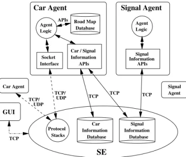
Fig. 1 shows the architecture of the platform. One sees that the architecture consists of four major components: GUI, SE, Car Agent(s), and Signal Agent(s). The roles of these components and their functionalities are described below.
• GUI (Graphic User Interface) The GUI provides users
with an environment where they can easily construct their desired road networks. For example, road segment construction/connection can be specified in a few steps of mouse operation. In addition, network protocol selec-tion/replacement and network system parameter setting can also be done in just a few operations. After all the settings of the road and network subsystems have been done, the GUI will automatically generate all configura-tion files for the other components. The GUI saves users much time in specifying a simulation case with many vehicles and roads. The GUI can play back animations of packet transmission and vehicle movement. This visual display of simulation results greatly help users check the correctness of their network protocol designs and vehicle movement behavior.
• SE (Simulation Engine) The SE is responsible for
simulating transport-layer and network-layer protocols. Besides, it stores some car and signal information for servicing the requests issued by a car agent or a signal agent.
• Car Agent A car agent is run on each car and it consists
of four components, which are (1) the agent logic, (2) a road map database, (3) socket interfaces, and (4) car/signal information APIs. The agent logic controls the automatic driving behavior of the vehicle node on which the car agent is run. The road map database stores the location/direction of roads. The socket interfaces provide TCP/UDP Internet connections for vehicles to exchange
Signal Agent Information Signal Database Information Database Car Protocol Stacks SE Agent Logic GUI Car Agent Signal Information APIs Socket Interface Agent Logic Database Road Map APIs Information Car / Signal Signal Agent TCP TCP TCP TCP/ UDP TCP/ UDP TCP Car Agent APIs
Fig. 1. The integrated platform architecture
their information on the road. The car/signal information APIs are the functions that the agent logic can call to access the car and signal information databases located in the SE. These API functions internally use TCP/IP IPC (Inter-Process Communication) connections to exchange information between the car agent and the SE.
• Signal Agent A signal agent is run up for each
cross-road. It controls the changing of the signal state of the four traffic lights located at the crossroad. It has two components: the signal logic and the signal information APIs. The signal logic governs when signal state should be changed. The signal information APIs are called by the signal agent to update the signal information database stored in the SE.
B. Road Types
NCTUns 4.0 supports different types of roads, including single-lane roads, multi-lane roads, crossroads, T-shape roads, and lane-merging roads. After constructing the desired road networks, users can obtain the road map configuration file generated automatically by the GUI. When a simulation starts, each car agent will read in this file and store the road map information into its own road map database for later uses. Fig. 2 shows a screenshot of the GUI.
C. Vehicle Movement Controls
Two approaches of vehicle movement control are supported by NCTUns 4.0. The first one is the pre-specified approach and the second is the autopilot approach. In the pre-specified approach, a user needs to specify the moving path and speed of each vehicle before a simulation starts. During simulation, each vehicle will move along its pre-specified moving path at the pre-specified moving speed(s) on a road network. In this approach, the car agent running on each vehicle does not con-trol the movement behavior of the vehicle. In contrast, in the
Fig. 2. A screenshot of the GUI
autopilot approach, a user need not specify each vehicle’s exact moving path/speed. Instead, he/she just needs to specify each vehicle’s moving parameters (e.g., initial speed, maximum speed, initial acceleration, maximum acceleration, maximum deceleration, etc.) for the car agent. During simulation, the car agent will automatically control the moving behavior of the vehicle based on these specified parameters. Each vehicle will dynamically determine its moving path and speed according to its current surrounding traffic and road conditions.
The intelligent driving behaviors coded in the agent logic of a car agent include car following, lane changing, overtaking, turning, and traffic light obeying. The intelligence used to control the first three behaviors considers the relationships between the speed and location of a given vehicle and those of each of its surrounding vehicles. The intelligence used to control the other behaviors considers the road conditions and the traffic light signal states ahead of the vehicle. On top of the default autopilot intelligence, a user can easily add more intelligence into the agent logic of a car agent. A user can also easily replace the default autopilot intelligence with more advanced autopilot intelligence.
D. Application Program Interfaces
From Fig.1, one sees that some intra- or inter-process APIs are provided to deliver requests and/or replies. These APIs can be classified into three categories as follows.
1) The intra-process APIs in a car agent are called by the agent logic to access the road map database. These APIs help the agent logic obtain the road configura-tions/conditions for making driving decisions. For ex-ample, the agent logic obtains the direction of a road ahead of the vehicle so that the vehicle can move in the correct direction. Another example is that the agent logic obtains the information of neighboring lanes so that the vehicle can safely change lanes and/or overtake other vehicles. Yet another example is that the agent
logic obtains the information of the crossroad ahead of the vehicle so that the vehicle can make a turn smoothly. 2) The signal information APIs in a signal agent are used by the agent logic to update the newest signal states onto the signal information database located in the SE. For the sake of reliability, the update data are transfered over TCP connections.
3) The car/signal information APIs in a car agent are called by the agent logic to update/access the car and signal information databases located in the SE. For each vehi-cle, its moving states are stored in the car information database. These states include current moving direction, current speed, current acceleration, current location, etc. Through the car information API functions, an agent logic regularly updates the states of its vehicle in the database and fetches the states of surrounding vehicles from the database. With these information, a vehicle can perform car following, lane changing, and overtaking without colliding with other vehicles. Through the signal information API functions, an agent logic can fetch the current states of some signals (e.g., traffic light) from the signal information database. With these information, a vehicle can either drive across a crossroad when the traffic light is green or stop at a crossroad when the traffic light is red. To ensure that these information are exchanged reliably between a car/signal agent and the SE, these information are transfered over TCP connec-tions.
E. Network Protocol Simulations
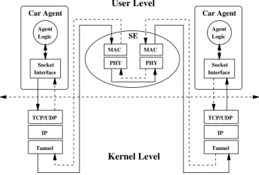
In Fig. 1, one sees that different car agents exchange Internet packets with each other over TCP or UDP connections. These TCP/UDP connections are set up by the car agents using the standard POSIX socket APIs. Fig. 3 shows how network protocol stacks and Internet connections are simulated on NCTUns 4.0. In the example, two vehicles moves on the road and they exchange Internet packets with each other. To simulate this case, two car agents are run up to control these two vehicles (one for each vehicle) and the SE is run up to simulate the MAC and PHY layers of the protocol stacks. Suppose that the left car agent sends a packet to the right car agent, the detailed packet delivery process is described below. 1) The agent logic of the left car agent uses the standard POSIX socket system calls (e.g., sendto, write, etc.) to write a segment of data into the socket send buffer in the kernel.
2) The data segment will first reach the TCP/UDP layer (which is defined as the transport layer in the OSI model). After being encapsulated with a TCP/UDP header, this TCP/UDP packet is then passed to the IP layer (which is defined as the network layer).
3) The TCP/UDP packet will be encapsulated again with a IP header and then be written into a tunnel interface. 4) Later on, the user-level SE will retrieve the IP packet
from the tunnel interface.
TCP/UDP IP Tunnel TCP/UDP IP Tunnel Interface Socket Agent Logic Car Agent Interface Socket Agent Logic Car Agent MAC PHY MAC PHY SE User Level Kernel Level
Fig. 3. The architecture of network protocol simulation
5) The media access control (MAC) protocol (which is defined as the datalink layer in the OSI model) and the physical (PHY) protocol (which is defined as the physical layer) are simulated in the SE. The fetched IP packet will be encapsulated again with a MAC header and then sent from the sending PHY to the receiving PHY under the control of the MAC protocol.
6) The MAC header of the MAC packet will be stripped off when the packet arrives at the receiving MAC. The SE then writes the packet into another tunnel interface in the kernel.
7) The kernel then delivers the IP packet from the tunnel interface to the IP layer. Although this packet is received from the (pseudo) tunnel interface, the kernel processes it in exactly the same way as it processes a packet received from a (real) network interface. The IP header of the IP packet is then stripped off at the IP layer, and then the packet is passed up to the TCP/UDP layer. 8) At the TCP/UDP layer, the TCP/UDP header of the
TCP/UDP packet is stripped off and the remaining data segment is then stored into the socket receive buffer. 9) Finally, the agent logic of the right car agent uses the
standard POSIX socket system calls (e.g., recvfrom, read, etc.) to read the data segment from the socket receive buffer.
From the above descriptions, one sees that NCTUns uses the real-life TCP/UDP/IP protocol stack in the Linux kernel to deliver packets among car agents. As such, NCTUns generates realistic TCP/UDP/IP protocol stack simulations results for wireless vehicular communication networks. Besides, one sees that a car agent is an independent user-level application program using the standard POSIX system calls to get ser-vices from the operating system. This means that it can be easily and quickly deployed in the real world without any modification once its functions have been verified in simulated environments.
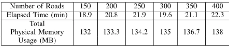
TABLE I
ELAPSED TIME AND TOTAL PHYSICAL MEMORY USAGE IN EACH CASE WITH DIFFERENT NUMBER OF ROADS
Number of Roads 150 200 250 300 350 400
Elapsed Time (min) 18.9 20.8 21.9 19.6 21.1 22.3 Total
Physical Memory 132 133.3 134.2 135 136.7 138
Usage (MB)
IV. PERFORMANCEEVALUATIONS
Due to the paper length limit, only the effects of two important system parameters are studied in this paper: the number of roads and the number of vehicles deployed in a simulated traffic network. For each simulation case, we observe the elapsed time for the simulation and the total physical memory usage.
The simulation machine used in our evaluations is an ASUS A8Jseries notebook, which is equipped with a 1.83 GHz CPU and 1 GB RAM. The simulated road topology is a rectangular single-lane highway with 6 Km of length and 6 Km of width, regardless of the number of roads deployed in a simulation case. This special arrangement of roads ensures that the vehicle density on the highway remains the same regardless of the number of roads. This property is important to fix the AODV routing protocol overhead.
Regarding the network communication scenario, no matter how many vehicles are deployed, all the car agents of these vehicles are programmed to send a 1084-byte UDP packet (1056 bytes for the data payload, 20 bytes for the IP header, and 8 bytes for the UDP header) to each of the other vehicles once per second. The AODV routing protocol [11] is used in the protocol stack of each vehicle to build packet routing paths among all vehicles. The total time to be simulated for each case is set to 500 seconds. Regarding the vehicle movement parameters, the initial speed is set to 10 m/s, the maximum speed is set to 18m/s, the initial acceleration is set to 1 m/s2, the maximum acceleration is set to 1.4m/s2, and the maximum deceleration is set to 4.5m/s2 for each deployed vehicle.
A. Number of Roads
In the first evaluation, in total 100 vehicles are deployed in each of the six simulation cases. In each case, we deploy a different number of roads — 150, 200, 250, 300, 350, and 400, respectively.
Because the total length of the deployed highway is kept the same in all cases, the density of vehicles on the highway is also the same in all cases. This makes the simulation overhead of the AODV routing protocol and the UDP packet transmissions similar in all cases. Since increasing the number of roads will increase the size of the road map database, we expect to see increased total physical memory usage and increased time for running the simulation (i.e., the elapsed time).
The results shown in TABLE I confirm the above expecta-tions. One sees that the elapsed time increases slightly with the number of roads. In addition, as expected, the total physical memory usage increases slightly with the number of roads.
TABLE II
ELAPSED TIME AND TOTAL PHYSICAL MEMORY USAGE IN EACH CASE WITH DIFFERENT NUMBER OF VEHICLES
Number of Vehicles 100 125 150 175 200 225
Elapsed Time (min) 22.3 32.2 47.4 65.6 84.3 105.1 Total
Physical Memory 138 175 207 241 276 313
Usage (MB)
B. Number of Vehicles
In the second evaluation, in total 400 roads are deployed in each of the six simulation cases. In each case, we deploy a different number of vehicles — 100, 125, 150, 175, 200, and 225, respectively.
Because the total number of roads is the same in all cases, the overhead of road map database in terms of access time and total physical memory usage is the same in all cases. Since increasing the number of vehicles will increase the vehicle density on the highway, it is expected to see increased overhead of the AODV routing protocol and the UDP packet transmissions, which should be reflected by increased elapsed time. Besides, since a car agent needs to be run up on every vehicle and each car agent needs to store the road map database, the total physical memory usage is expected to increase with the number of vehicles.
The results shown in TABLE II confirm the above expec-tations. One sees that the elapsed time and the total physical memory usage increase with the number of vehicles.
V. CONCLUSION
In this paper, we present an integrated simulation plat-form, called NCTUns, for vehicular traffic, communication, and network researches. NCTUns combines the simulation capabilities provided by both a network simulator and a traffic simulator. As such, it can simulate microscopic vehicular wire-less communication networks for advanced ITS researches. The scalability of NCTUns under different numbers of roads and vehicles is also presented.
REFERENCES
[1] S.Y. Wang, C.L. Chou, C.H. Huang, C.C. Hwang, Z.M. Yang, C.C. Chiou, and C.C. Lin, “The Design and Implementation of the NCTUns 1.0 Network Simulator,” Computer Networks, Vol. 42, Issue 2, June 2003, pp. 175-197.
[2] The NCTUns 3.0, available at http://nsl10.csie.nctu.edu.tw/.
[3] The Network Simulator - ns-2, available at http://www.isi.edu/nsnam/ns. [4] The QualNet software, available at http://www.scalable-networks.com/. [5] The cnet network simulator, available at http://www.csse.uwa.edu.au/
cnet/.
[6] The OPNET modeler, available at http://www.opnet.com/.
[7] The ptv simulation - VISSIM, whose reference link is http://www. english.ptv.de/cgi-bin/traffic/traf vissim.pl.
[8] The TransModeler traffic simulator, whose reference link is http://www. caliper.com/transmodeler/.
[9] The SUMO traffic simulation package, available at http://sumo. sourceforge.net/index.shtml.
[10] The TraNS (Traffic and Network Simulation Environment), available at http://wiki.epfl.ch/trans.
[11] C. Perkins, E. Belding-Royer, and S. Das, “Ad hoc On-Demand Distance Vector (AODV) Routing,” IETF Internet draft, draft-ietf-manet-aodv-12.txt, November 2002.