國
立
交
通
大
學
資訊工程系
碩
士
論
文
使用泛送機制為車間通訊應用程式
設計與開發繞送協定
A Flooding-based Data Forwarding Protocol for
Inter-Vehicle Communication Applications
研 究 生:黃郁文
指導教授:王協源 教授
使用泛送機制為車間通訊應用程式設計與開發繞送協定
A Flooding-based Data Forwarding Protocol for
Inter-Vehicle Communication Applications
研 究 生:黃郁文
Student:Huang Yu-Wen
指導教授:王協源
Advisor:Wang Shie-Yuan
國 立 交 通 大 學
資 訊 工 程 系
碩 士 論 文
A ThesisSubmitted to Department of Computer Science and Information Engineering College of Electrical Engineering and Computer Science
National Chiao Tung University in partial Fulfillment of the Requirements
for the Degree of Master
in
Computer Science and Information Engineering June 2005
Hsinchu, Taiwan, Republic of China
摘
要
智慧型運輸系統(Intelligent Transportation Systems,ITS)利用道路資料與 路況資訊的即時傳遞,來增進道路運輸與車輛移動的效率,進而改善交通擁擠的 程 度 , 並 提 高 行 車 安 全 以 及 促 進 相 關 的 經 濟 活 動 。 車 間 通 訊 (Inter-Vehicle Communication,IVC)為智慧型運輸系統發展的主流之一,其發展演進亦提供了許 多相關的應用。一個車間通訊網路可被視 為一個行動隨意無線網路(Mobile Ad-hoc Network,MANET)的特殊形式,現有的 MANET 相關技術可直接引用於 這類型的網路。然而,由於此類網路拓撲具有快速變化的特性,使得舊有的繞送 協定(如 AODV)不再適用。 我們應用泛送機制來發展新的繞送協定,本篇論文中具體的實驗及模擬結果 證實,應用泛送機制來繞送封包可以適應變化快速的網路。然而此機制先天上的 特性會導致重複傳送冗餘的封包及嚴重的封包脫序(Packets' out-of-ordering)問 題。我們嘗試在不影響行動效能的情況下,改善這些衍生的問題,並已獲得初步 的成果。
ABSTRACT
Inter-vehicle communication (IVC) provides useful applications in future Intelligent Transportation Systems (ITS). An IVC network is a special case of mobile ad hoc networks (MANET) with high node mobility. Although various existent MANET technologies can be applied to an IVC network directly, traditional routing protocols such as AODV can not adapt to this rapidly-changing network. To address this problem, we designed and implemented a flooding-based data forwarding protocol. The practical experiments and simulation results in this thesis showed that the proposed protocol is suitable for IVC networks. However, the derived problems such as redundant and out-of-order packets affect the performances and efficiency of the protocol greatly. This thesis also proposes several improvements for those problems.
誌
謝
首先感謝王協源教授這兩年來的指導。在撰寫這篇論文的過程中,我學到了 許多研究學問的技巧和做人處事的方法;同時也要感謝我的口試委員賴威光教 授、吳曉光教授的建議,使整篇論文更加趨於完整。 此外,非常感謝實驗室學長們的意見與指導,尤其是林志哲學長,他在這方 面的深入研究,是這篇論文的基石。此外,特別感謝他在百忙之中,仍熱心為學 弟妹們審閱畢業論文。另外也要感謝陶奎志同學,他負責了 FloodingRD 架構的 實作及相關技術的支援。還有接下來進一步發展相關應用的林仕盈學弟。謝謝你 們所有的付出與努力。 謝謝好友玉雯及詩婷,感謝你們在期末考前仍抽空為我審閱英文修詞。感謝 男友奇峰,你對我毫不保留的支持,一直是我最大的鼓勵。 最後,感謝家人對我的鼓勵,在我面臨挫折時,能夠不斷的支持我,還有所 有關心我的朋友和實驗室的同窗們,因為有你們的關懷與支持,我找到了明確的 方向,也才能將所有的努力化為動力,付諸實行。Table of Contents
摘 要 ...i
ABSTRACT ... ii
誌 謝 ... iii
Table of Contents ...iv
Figure List ...vi
Table List ...vii
Chapter 1 Introduction ...1
1.1 Motivation ...1
1.2 Organization ...3
Chapter 2 Related Work ...4
2.1 Routing Protocols on MANET ...4
2.2 Single-path Routing Protocols ...4
2.3 Multi-path Routing Protocols ...6
2.4 Flooding Techniques ...6
2.5 Discussion...8
Chapter 3 Architecture ...9
3.1 A User-Level Routing Daemon ...9
3.2 Two Overlapping Network Domains ...10
Chapter 4 Design ...13
4.1 Reliability Enhancement ...13
4.1.1 Detail of Retransmission Queue Implementation ...15
4.1.2 Parameters ...18
4.1.3 Results ...19
4.2 Redundancy Reducing ...21
4.2.1 Detail of Forward-wait Queue Implementation...22
4.2.2 Parameters ...23
4.2.3 Results ...24
4.3 Reduction of Small Packets...26
4.4 Issues about Parameters ...27
4.4.1 Components Overview and Relationship between Parameters ...27
4.4.2 How to Decide the Value of a Parameter ...29
4.4.3 Recommended Value for Main Parameters ...29
4.5 Tuning Parameters Automatically...30
4.5.1 Introduction ...30
4.5.2 Appropriate Retransmission Waiting Time ...30
4.5.4 Results ...33
Chapter 5 Implementation ...38
5.1 Packet Filter ...38
5.2 Limitations of Current NICs...39
Chapter 6 Performance Evaluation ...41
6.1 Performance Metrics ...41
6.1.1 Throughput ...41
6.1.2 End-to-End Latency ...42
6.1.3 Packet Loss Rate ...42
6.1.4 Redundancy Degree ...43
6.1.5 End-to-End Re-ordering Degree ...43
6.1.6 Mobility ...44
6.2 Experiment Environment ...44
6.2.1 Hardware and Software ...44
6.2.2 Traffic Type ...45
6.2.3 FloodingRD Configuration...45
6.3 Real Experiments Result Analyses ...47
6.3.1 Throughput ...48
6.3.2 Packet Loss Rate ...50
6.3.3 Latency ...51
6.4 Simulation...52
6.4.1 Simulations about Auto Tuning ...52
6.4.2 Integrated Simulation Result ...54
6.4.3 Road Topology Simulation ...56
6.4.4 Mobility Demonstration ...57
Chapter 7 Discussion ...59
7.1 Comparison with AODV ...59
7.2 Lessons ...60
7.2.1 Verify Every New Mechanism...60
7.2.2 Prevent Unnecessary Costs...60
7.3 Future Works...61
Figure List
Figure 1. The processing flows in the source, the forwarder, and the
destination...9
Figure 2. The architectural view of packet processing at the source... 11
Figure 3. The direction of packets ...16
Figure 4. The average TCP throughput in a chain network ...20
Figure 5. Average packet loss rate under greedy TCP traffic ...21
Figure 6. An example of inserting a packet into fwwQueue...23
Figure 7. Topology...25
Figure 8. UDP Throughput...26
Figure 9. UDP Redundancy ...26
Figure 10. The overall structural view inside FloodingRD...28
Figure 11. A simple topology to show different types of forwarders ...32
Figure 12. Average UDP throughput to compare functions of Auto Tuning35 Figure 13. Average Latency under one-way greedy UDP ...35
Figure 14. Average RTT time at the source under one-way greedy UDP....36
Figure 15. Average TCP throughput in a chain network...37
Figure 16. The scenario built up by net filters ...48
Figure 17. Average UDP Throughput by RF FloodingRD...49
Figure 18. Average UDP Throughput by AT FloodingRD ...50
Figure 19. Packet loss rate under greedy UDP...51
Figure 20. Latency under greedy UDP traffic ...51
Figure 21. Average UDP throughput by simulation ...53
Figure 22. Latency under greedy UDP by simulation ...54
Figure 23. Average UDP throughput by RF FloodingRD (simulation) ...55
Figure 24. Average UDP throughput by AT FloodingRD (simulation) ...55
Figure 25. Topology of road simulation...56
Figure 26. Snapshot of TCP throughput in road simulation ...58
Figure 27. Route Recovery Time of AODV...59
Table List
Table 1. Parameters of retxQueue...19
Table 2. FloodingRD types used in TCP experiments ...20
Table 3. Parameters of fwwQueue...24
Table 4. Types of FloodingRD ...25
Table 5. Reference value of main parameters ...30
Table 6. Types of FloodingRD ...34
Table 7. The hardware and software used in experiments ...45
Table 8. FloodingRD with different configuration used in experiments ...46
Table 9. Settings of real experiments...48
Table 10. Settings of simulation for Auto Tuning experiments...52
Table 11. Details of integrated simulations ...55
Table 12. Details of road simulations ...56
Table 13. Road simulation result with 10 nodes in 36 km/hr...57
Table 14. Road simulation result with 10 nodes in 108 km/hr...57
Chapter 1 Introduction
1.1
Motivation
ITS (Intelligent Transportation System) aims to provide travelers with a safer, more efficient, more comfortable trips. Its basic functions include instant traffic congestion notification, road condition information broadcasting, as well as emergency alert. Recently, ITS wants to provide network services to enable inter-vehicle communications (referred to as IVC) for exchanging information, sending/receiving emails and browsing web pages on the Internet, etc.
IVC has become a popular topic in the ITS research community. It enables communications among vehicles without the support of an infrastructure network, such as the ones using 802.11 infrastructure-mode access points. Each vehicle is equipped with a wireless interface, and vehicles on roads dynamically form a Mobile Ad Hoc Network (MANET) with high mobility. In an IVC network each node (vehicle) may move at a wide range of speeds and in different directions. Therefore, an IVC network is featured as extremely high mobility, which introduces many challenges for designing a routing protocol.
We have done lots of field trials with AODV (Ad-hoc On-demand Distance Vector Routing [1]) protocol on the highway and on the roads in downtown but found that such traditional routing protocols are not suitable for IVC networks. The topology of an IVC network changes rapidly so that the built paths in such a network are broken very easily. The results of these experiments exhibit that in a network with
universal mobility the available lifetime of a single-hop route is about 20 seconds, while that of a two-hop route is only around 4 seconds. As the result, the lifetime of routing paths in such a network is usually too short for data transmissions. Moreover, routes with three hops or more are almost not available in AODV.
Traditional routing protocols repair broken routes based on the propagation of messages containing the correct, freshest routing information. However, when those messages are being propagated to reflect topology changes, the information they contain is very likely to be outdated due to the nature of the frequently changed network topology. To address this issue, we propose a new routing protocol to route packets based on the flooding technique.
Flooding is featured as high reliability with minimized states so that it is suitable for high mobility networks. For this reason, we design and implement a new flooding-based data forwarding protocol to provide effective data transmission in IVC networks.
Since audio and video applications are more and more popular, we characterized the demands and requirements of those two kinds of UDP-based applications, respectively, to provide them with the best services. Audio service applications generally need less bandwidth than video applications. However, the voice quality is very sensitive to the round trip times between the source and the destination nodes.
wireless environment, using TCP for web accesses and text-mode services is still acceptable because the amount of transferred data in those applications is relatively small. FTP is another important network service, but transferring a large file in an IVC network is not a common case.
To meet the requirements needed by these different applications, our proposed protocol has to provide bandwidths at least 50 KB for UDP. The maximum bandwidth achieved by our protocol is limited by that provided by the underlying network. Currently, we evaluate our protocol in field trials based on the IEEE 802.11b network, whose theoretical maximum bandwidth is 11 Mbps only. It is possible to increase the achievable bandwidth of our scheme by using more advanced wireless technology for the underlying network. For example, IEEE 802.11a/g networks provide 54Mbps bandwidths, which is much larger than that provided by IEEE 802.11b networks.
1.2
Organization
The remaining parts of this paper are organized as follows. We briefly introduce the famous routing protocols for MANET and the commonly used flooding techniques in Chapter 2. Chapter 3 depicts the architecture of the proposed flooding-based routing mechanism. Chapter 4 itemizes the detail of our protocol design. Chapter 5 discusses related issues about implementation. Chapter 6 presents the evaluation of the performances by both practical experiments and simulations. The discussions and future works are put in Chapter 7. Finally, Chapter 8 makes a short conclusion about our works.
Chapter 2 Related Work
2.1
Routing Protocols on MANET
Recently, numerous routing protocols have been proposed for MANET. Typically, they can be partitioned as two types: single-path routing and multi-path routing. Single-path routing protocols are divided into two groups, “table-driven” and “demand-driven” protocols. Besides, a multi-path routing protocol is normally a modification from one of single-path protocols. Moreover, there are some broadcast and multicast technologies used to deliver messages on a wireless environment. In this chapter, we discuss these related techniques and how they differ from our scheme.
2.2
Single-path Routing Protocols
Traditional routing protocols for MANET are generally categorized as “table-driven” or “demand-driven.” Table-driven routing protocols maintain routing information on each node and change messages to update these information periodically. On the contrary, demand-driven routing protocols keep no topology information on hosts until there is a requirement of communication. These kinds of protocols try to find a path only when a node wants to send packet out. Popular AODV (Ad Hoc On-Demand Distance Vector [1] ) routing protocol is one of typical
periodically changes messages, named hello messages, about their local information, e.g. the states of neighbors, the number of neighbors, and so forth. These messages occupy lots of limited bandwidth. DSDV (Destination-Sequenced Distance-Vector Routing Protocol [4] ) is the standard one of table-driven protocols. Famous table-driven routing protocols include DSDV and CGSR (Clusterhead Gateway Switch Routing), etc.
CGSR derived form DSDV separates the whole network into two hierarchical architectures, the cluster head and the others. When a change occurs on a normal node or a gateway, there is no maintenance overhead. On the other hand, if a change happens on the cluster heads, the overhead will be higher then that of DSDV protocol. In IVC networks, because there is almost no fixed node and every vehicle can move out of scope of the network at any time, after applying CGSR to IVS network, it is hard to choose appropriate cluster heads. And CGSR is therefore not suitable for the IVC environments.
Compare with table-driven protocols, demand-driven (also called “reactive”) routing protocols seem to adapt to speedy IVS network. They don’t need to maintain information about the whole network. The routing path is built only when there are packets waiting for routing. The overhead of a great deal of control packets is saved. However, because the life time of a built path is too short to be useful, these protocols are still not suitable for IVC networks. Famous demand-driven routing protocols include AODV and DSR [5].
2.3
Multi-path Routing Protocols
A multi-path routing protocol, such as GeoTORA [6], discovers multiple routing paths to forward data for higher reliability. Most of them are variations derived from single-path routing protocols. For example, [7] [8] [9] [10] are extended from AODV, [11] [12] are the extensions of DSR, and [13] is a variation that combines both to achieve multi-path routing.
Although multi-path routing protocols are more adaptive than single-path routing protocols in high mobility networks, they suffer from the same problems in high mobility IVC networks, because the mechanisms behind them is similar to those behind single-path routing protocols.
2.4
Flooding Techniques
Flooding techniques are usually used to the research area of broadcast and multicast. While these studies focus on how to reach the most coverage by the least number of duplicated packets, our design apply it to forward data packets to a particular target.
Some flooding techniques that need to exchange local information by control messages will meet the same problems we have mentioned in last sections. Others that
coverage of a broadcast and the number of duplicated packets by configurable parameters, such as the dropping probability, the maximum number of rebroadcasts, and the maximum hop counts for a broadcasted packet, etc. It is difficult to fine-tune these parameters in IVC networks due to greatly frequent topology changes.
Location-based techniques usually assume that the location information of neighbors is available. Although GPS (Global Positioning System) can be used to provide local position information, it is still a difficult task to get location information of the destination and other forwarders before starting packet forwarding. Besides, the GPS support is not available all the time; it needs additional equipments and may be influenced by the weather. Therefore, we suggest that the location information can only be regarded as an additional aid while implementing a routing protocol for IVC networks.
Cluster-based schemes divide nodes in a network into three types: cluster head, gateway, and ordinary nodes. A cluster head is responsible for community inside a cluster, while a gateway delivers packages between clusters. Nodes except for cluster heads and gateways are called ordinary nodes. According to the adopted approaches of constructing clusters, cluster-based schemes can be classified into two groups: active-clustering and passive-clustering. Due to greatly high mobility in IVC networks, the procedures of electing a cluster head may be performed very frequently. Therefore, the protocols may spend most bandwidth on maintaining clusters and generate great latencies for data forwarding. Passive clustering carries the cluster-related information in data packets and doesn’t need to exchange additional control packets to maintain clusters. This scheme minimizes control message overheads but leads to a new problem of cluster head failures (or disappearances).
This problem becomes worse when the mobility of a network increases. Therefore, cluster-base techniques are not suitable for IVC networks, either.
2.5
Discussion
Because of power-consumption and bandwidth waste, table-driven protocols are not satisfactory for IVC networks. Demand-driven protocols have longer latency and can save bandwidth waste but still do not satisfy the requirement of high mobility in IVC networks. Multi-path routing protocols based on similar mechanisms with single-path protocols encounter the same problems. Flooding techniques are normally applied to research area of broadcast and multicast. The related issues can provide some hints and ideas to our study.
By analyses of these related technologies, we can conclude that: to develop a routing protocol for IVC networks, a researcher might give up techniques of traditional MANET routing protocols and should consider the extremely high mobility condition
Chapter 3 Architecture
3.1
A User-Level Routing Daemon
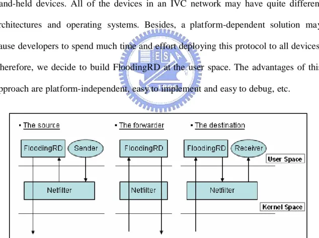
The first issue of implementing a flooding-based routing daemon is to broadcast a unicast packet. Intuitively, developers can modify the functions of the IP layer in the kernel to add a broadcast IP header in front of the original packets. However, a platform-dependent implementation is not suitable for an IVC environment. Consider that an IVC network is composed of a variety of vehicles and even pedestrians with hand-held devices. All of the devices in an IVC network may have quite different architectures and operating systems. Besides, a platform-dependent solution may cause developers to spend much time and effort deploying this protocol to all devices. Therefore, we decide to build FloodingRD at the user space. The advantages of this approach are platform-independent, easy to implement and easy to debug, etc.
Figure 1. The processing flows in the source, the forwarder, and the destination
To capture packets from applications and prevent applications from knowing the existence of FloodingRD, the net filter technology inside kernel is used to redirect packets from the user level to our daemon. Figure 1 shows the processing flows in the source, the forwarder, and the destination.
At the source, a packet is injected into the kernel by the application and then transferred to the daemon at the user level by the net filter. FloodingRD will append information needed by the protocol design to this packet. After that, this packet would be broadcasted out. An IP header with a broadcast address makes every host that can hear this packet accept it and deliver it to the FloodingRD. After receiving a packet, the daemon will exam whether this packet is for the local host or not. If it is, the original unicast packet will be extracted and then injected into the kernel. The net filter inside the kernel recognizes the packet as a local packet and brings it to the target application. Otherwise, if the packet is not a local packet, the daemon will decide whether to broadcast it again according to the protocol design with present status and information.
3.2
Two Overlapping Network Domains
To make the net filter recognize the source of incoming packets more easily, the concept of two overlapping network domains is introduced into our scheme. The first domain used by applications is the original domain, while the second domain is set for FloodingRD. The net filter redirects packets with the first domain IP address from applications to FloodingRD. On the other hand, after processing the packets, FloodingRD re-send them by the second domain IP address to let the net filter pass them through.
Figure 2. The architectural view of packet processing at the source.
Figure 2 shows the processes of delivering a unicast packet at the source node in detail. 1) Firstly, a data section is sent from an application into the kernel. Without any additional configuration, applications will use the original network domain naturally. Consequently, the IP layer encapsulates this data section with unicast IP addresses of the first network domain. Secondly, according to predefined rules, 2) this packet will be captured by the net filter and redirected into FloodingRD. And then, 3) the daemon appends a FloodingRD-specific header to this unicast packet. After some processes in FloodingRD, 4) this packet will be sent out as a UDP broadcast packet with the second domain IP address that makes the net filter pass it through.
The appended specific header contains all information needed by the protocol design, such as the sequence number, the hop count information and IP address of the host which is the last one to broadcast this data packet out. Here the last host is definitely the source. After the packet begins its traveling around the network, the last host will be the last forwarder. The sequence number cooperates with the source address recorded in the IP header is used to identify a packet. According to this
information, FloodingRD will not accept the same packet more than once.
There is another advantage of two overlapping network domains. Because the packets of the second domain are not affected by the net filter, we can use existent tools, such as the ping program, with the second domain IP address to check network condition and avoid the influence of net filter. This additional functionality is helpful to detect the network condition during the practical experiments.
Chapter 4 Design
As we mentioned early, a flooding-based routing protocol has its advantages, especially when the network topology changes rapidly. However, this kind of routing protocols has their constitutional drawbacks that the protocol designers must overcome. In this chapter, we list the main difficulties for designing such a flooding-based routing protocol and then propose our solutions.
Before our discussion, we define some terms used in this article. We call a mobile node, which generates a packet, a “source node”. And a mobile node is a “destination node” if it is the destination of the packets generated by a source node. The other hosts in the network are called “forwarders.” A forwarder may not actually forward a packet every time. But it has the responsibility and the opportunity to forward packets. Finally, a node is called “sender” if it sends/forwards a packet out. Any other modes which hear this packet are called “listeners.”
4.1
Reliability Enhancement
The IEEE 802.11 wireless network provides the reliable transmissions with a simple positive acknowledgement mechanism. In the IEEE 802.11 wireless network, every unicast data frame must be acknowledged, or the frame is considered to be lost. Every time a data frame is supposed to be lost, the 802.11 MAC protocol will retransmit the data frame again. The maximum retransmitted count is four for large packets and seven for small packets because small packets may meet collisions in higher probabilities. Moreover, in the IEEE 802.11 MAC protocol broadcasted packets are not protected by the positive acknowledgement mechanism.
Even though the designers want to implement protection mechanism in high level, it’s still impossible the figure out who should take the responsibility of answering the acknowledgement. Moreover, if every listener sends ACKs back, in a high-density network it inevitably leads to an “ACK implosion” problem and a large number of ACK frames may spend much valuable bandwidth. Therefore, the original retransmission scheme with ACK packets cannot take effect any more. This may degrade performance of upper-layer sensitive protocols, such as TCP. TCP decreases the size of the congestion window at the sender to half if a packet loss is detected. Without transmission protection, the performance becomes worse. To improve error toleration and protect these sensitive protocols, retransmission of a lost packet is necessary. For this, a protocol designer must provide other mechanisms instead of the ACKs to confirm whether a packet is transmitted correctly.
Our mechanism regards packet forwarding as a kind of responsibility delivery. We make use of the packets forwarded by next forwarders to make sure whether the transmission is correct. If a destination receives a packet, it should send a one-hop ACK back to announce that there is unnecessary to retransmit this packet or forward it further.
This method needs no additional ACK packets. Its drawback is that a sender cannot be aware of the success of the transmission immediately and must wait until a forwarder finishes processing of this packet. This delayed time will affect UDP
4.1.1
Detail of Retransmission Queue
Implementation
“RetxQueue” is a retransmission queue introduced into FloodingRD for higher reliability. This queue preserves packets which are going to be sent and packets which were already sent but not acknowledged. Each packet would be marked with a waiting time. This time counts down until FloodingRD can make sure the transmission is successful. Otherwise, if the time goes down to zero, this packet would be sent again. The queue length is limited; if one packet is inserted into retxQueue and makes the queue exceed its length, this packet would be discarded.
While implement such a queue some issues must be taken. Firstly, this queue should be separated into sub-queues by packets’ destination address to prevent HOL problem (Head-of-Line problem). Secondly, there are lots of technologies to raise efficiency by speeding up the movement of the queues. Sliding window can help this. After introducing the sliding window into retxQueue, the designer can use fast-retransmission to accelerate it.
Separated retxQueue by Destination Address
After adding retransmission functionality into FloodingRD, we observe a particular phenomenon: when a packet is delivered in a right direction, it will be transmitted faster than in a wrong direction. Figure 3 shows this fact. It is because the movement rate of retxQueue would be affected by processing speed of next forwarder. After sending a packet out, the sender will preserve this outgoing packet in retxQueue and wait for acknowledgement from destination or next forwarders. If the listener is
the destination, it will answer an ACK quickly to let the sender process next packet in retxQueue. On the other hand, if the listener is a forwarder, it takes longer time to wait for this packet to be forwarded out. However, if there is no next listener, the retxQueue on the sender will be blocked until this packet time out. Depending on the configuration of retransmission waiting time, the one-way greedy UDP throughput can be down to 10%.
Figure 3. The direction of packets
This phenomenon can help to reduce unnecessary forwarding and decrease waste of bandwidth. However, in some situation this may cause HOL problem (Head-of-Line problem). While retxQueue is blocked by a packet on its wrong way, other packets which belong to different destination behind this blocked packet should not be delayed. Therefore, we changed our earlier design and divided retxQueue into sub-queues by destination address of packets.
The Sliding-window
transfers. Famous TCP protocol uses it to enhance performance. It overlaps the waiting of acknowledgements and the transmissions of the following packets by transmitting at most the window-size number of packets at a time.
Fast-retransmit
Because of high packet loss rate, after implementing sliding window algorithm in retxQueue, the performance was still not good enough. To improve efficiency, fast retransmission mechanism was also implemented to cooperate with the sliding window algorithm.
If a packet or packet’s acknowledgement is lost, the original sliding window mechanism must wait for timeout to start retransmission. However, in some conditions even though the waiting time is not finished, once acknowledges of other packets in sliding window come back, it can be predicted that this packet may be lost and the retransmission should be launched. This design is called “fast retransmission.” It is also applied to TCP protocol.
Maintain Packets’ Ordering
Re-ordering is an important problem in a flooding network. In our implementation, there is a mechanism used to sort incoming packets at destination. Moreover, because there are lots of queues inside FloodingRD preserve packets for different purpose, FloodingRD decrease probability of re-ordering by maintaining packets’ sequence in these queues.
While inserting a packet into retxQueue, FloodingRD will seek an appropriate position for this packet instead of inserting it at the end of the queue directly.
De-retransmission Control Message
Sometimes, the reason for starting a retransmission is because the following forwarding packet encounters collision rather than the sent packet is lost. However, after being retransmitted, the sent packet will be discarded as an invalid packet at the forwarder. To prevent retxQueue on the sender from being blocked by a successfully transmitted packet, the forwarder should send a message to stop this retransmission on the sender. These controlled messages are called de-retransmission packets.
For implementation, the packet and the de-retransmission message contain information to identify the sender. This can prevent de-retransmission message from influencing regular forwarding of this packet.
4.1.2
Parameters
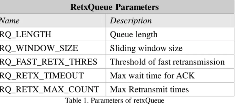
Table 1 lists the names and the brief descriptions of main configurable parameters in retxQueue. RQ_LENGTH defines the maximum length of retxQueue. RQ_WINDOW_SIZE means the size of sliding-window. RQ_FAST_RETX_THRES is the threshold for fast-transmission. If the number of returned ACKs reaches the
waiting time for ACK. Finally, the last one, RQ_RETX_MAX_COUNT, limits the maximum number of times to retransmit a packet.
RetxQueue Parameters
Name Description
RQ_LENGTH Queue length
RQ_WINDOW_SIZE Sliding window size
RQ_FAST_RETX_THRES Threshold of fast retransmission RQ_RETX_TIMEOUT Max wait time for ACK
RQ_RETX_MAX_COUNT Max Retransmit times Table 1. Parameters of retxQueue
4.1.3
Results
To make sure our retransmission mechanism really works, we conducted a simple experiment to show how retransmission influences packet loss rate and throughput. Because this mechanism was designed for sensitive protocols, we chose greedy TCP to demonstrate the performance. In this section, we only list variable factors of these experiments. Details of experiment environment are listed in section 6.2. Definitions of measure metrics are depicted in section 6.1.
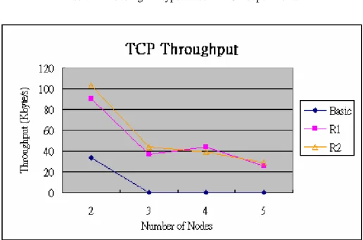
For comparing all functionalities, there are a lot of FloodingRD with different configurations to be tested in this paper. Table 8 in section 6.2.3 lists features of these daemons. There are three daemons used in this experiment. Firstly, the Basic daemon is a version without retransmission. Secondly, “R1” means retransmit lost packet only once. Lastly, R2 FloodingRD will have two opportunities to retransmit a lost packet. The topology is a chain network with 2 nodes to 5 nodes.
Symbol Describe
R1 Retransmit once R2 Retransmit twice
Table 2. FloodingRD types used in TCP experiments
Figure 4. The average TCP throughput in a chain network
Figure 4 shows the relationship between throughput and retransmission times. When the number of nodes is more than three, TCP throughput will drop to zero. Actually, the situation is not so bad in three-node cases. TCP traffic has about 20 Kbytes throughput at first 5 or 15 second. However, once the throughput drops, it will never rise again. With retransmission, the throughput sometimes falls; however, it will go up sooner or later.
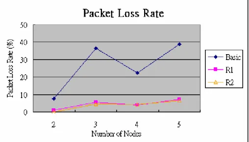
Figure 5 shows relationship between packet loss rate and retransmission times. According to these experiment results, retransmission indeed protects TCP traffic. Besides, increasing the maximum times of retransmission can’t reduce the packet loss rate more.
Figure 5. Average packet loss rate under greedy TCP traffic
4.2
Redundancy Reducing
Because of inherent drawbacks of flooding mechanism, large number of redundant packets is always a serious problem. There are lots of technologies proposed for limiting flooding packets. Some of them have been discussed in Chapter 2. However, almost all these technologies maintain status of other nodes and need additional control messages to exchange neighbor information such as related position or interval hop counts. Although additional information is really helpful for reducing redundant packets, our daemon that aims to reach high mobility should not depend on these mechanisms. Therefore, the designers have to solve this problem by another way.
When a FloodingRD is going to forward a packet, it takes a randomized value within a predefined range as the extra delay time. During this extra delay time, the daemon cancels the forwarding of this packet if it perceives a duplicate by one of the neighboring nodes. Because the extra delay is a randomized value that is only performed on forwarding packets, the designers call this period a “forward-random delay.”
For implementation, we add a queue to FloodingRD for extra delay. The designers call this queue a “forward-wait queue”, referred to as fwwQueue. As we mentioned earlier, the destination will answer an ACK for terminating the forwarding of a packet. To prevent forwarders from sending unnecessary packets before receiving this ACK, FloodingRD will delay a forwarding packet for a fixed time to see if whether the destination received the same packet. This period, named “forward fixed delay”, is also carried out by fwwQueue.
The details about implementing fwwQueue are put in next section. At the end of this portion, there are some experiment results about the performance of extra random delay.
4.2.1
Detail of Forward-wait Queue Implementation
Basic Scheme
For intuition, fwwQueue can be implemented as an aging and sorted queue. Each forwarding packet associated with an extra delay time is inserted into sorted fwwQueue according to the value of the time tag. Every time unit, fwwQueue decreases each packet’s waiting time tag. Once a packet’s time is counted down to zero, FloodingRD takes this packet out for further processing.
when a packet is inserted into the queue we let packets change their waiting time tag according to packet’ sequence number.
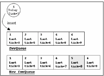
Figure 6 gives a simple example. Packet No.5 with 7 ticks waiting time is inserted into fwwQueue. During the insertion, it meets packet No. 4 with remaining 8 waiting ticks. After exchanging the waiting time tag with packet No. 4, packet No. 5 has 8 waiting ticks and would be sent out after packet No. 4. And then, it meets packet No. 6. Packet No. 5 should be inserted between packet number 4 and packet number 6, because its waiting time is shorter than packet No. 6’s. There is no need to change wait time tags further.
Figure 6. An example of inserting a packet into fwwQueue
4.2.2
Parameters
Because the extra delay time is an absolute protocol overhead, they should be minimized as much as possible. The parameters related to fwwQueue are listed in Table 3. FW_FIXED_DELAY is used to wait for ACK packets sent from destinations. FW_RANDOM_DELAY defines the range of random delay that is used by
forwarders to compete with each others. The total delay time can be computed as follows:
Extra Delay Time =
FW_FIXED_DELAY + random() % FW_RANDOM_DELAY
FwwQueue Parameters
Name Description
FW_FIXED_DELAY For waiting ACK from destinations FW_RANDOM_DELAY For competing with other forwarders
Table 3. Parameters of fwwQueue
4.2.3
Results
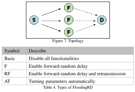
We designed a simple experiment to test the performance of forward-random delay. The topology is shown in Figure 7. There are three forwarders between the source and the destination. The traffic type is greedy UDP. Four daemons with different configuration are tested in this scenario. The briefs of these daemons are listed in Table 4. Configuration details are listed in section 6.2.
The daemon Basic has been used in last experiment in section 4.1.3. The daemon F enables forward-random delay while the daemon RF enables both forward-random delay and retransmission mechanisms. The daemon AT is a FloodingRD with ability of turning parameters automatically. The name of this daemon means “Auto Tuning.” In this scenario, technology Auto Tuning lets the forwarders compete with each others.
Figure 7. Topology
Symbol Describe
Basic Disable all functionalities F Enable forward-random delay
RF Enable forward-random delay and retransmission AT Turning parameters automatically
Table 4. Types of FloodingRD
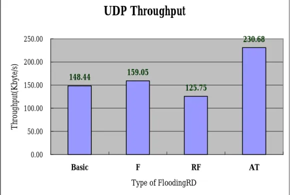
Figure 8 illustrates comparison among these four daemons about UDP throughput while Figure 9 shows the condition of redundancy. Daemon F applied forward-random delay but doesn’t reduce the redundancy. Because the configuration was set for daemon RF, 40 ms as FW_RANDOM_DELAY for daemon F was not enough to cancel transmission on other forwarders.
Although daemon RF can reduce redundancy, its UDP throughput was the lowest. Because of the high collision probability, UDP throughput suffered from retransmission mechanism. When the value of RQ_RETX_TIMEOUT got longer, FloodingRD should wait longer for a lost packet and the circumstance would become worse.
Here we provide two related experiment result as contrasts to Figure 8. Daemon Basic can get average throughput of 177.60 Kbytes/s under the same environment without additional forwarders, while daemon AT can reach 226.65 Kbytes/s. According to these experiment results, we can conclude that Auto Tuning indeed reduce redundancy and the additional overhead.
UDP Throughput
148.44 159.05 125.75 230.68 0.00 50.00 100.00 150.00 200.00 250.00 Basic F RF AT Type of FloodingRD T hr ou gh pu t( K by te /s )Figure 8. UDP Throughput
Redundancy
33.55 32.53 25.78 11.55 0.00 5.00 10.00 15.00 20.00 25.00 30.00 35.00 40.00 Basic F RF AT Number of Nodes R ed un da nc y( % )decrease throughput of whole system. To reduce the influence of these small packets, the designers merged these small packets with large data packets or combined them together into a large one.
Although our early study proved its potency, to minimize variable factors during developing period, this functionality has been disabled for a long time.
4.4
Issues about Parameters
4.4.1
Components Overview and Relationship
between Parameters
Before discussing about the parameters, the overview of components and relativity among them should be given firstly. As shown in Figure 10, there are two kinds of data packets: the packets from other hosts are “forwarded packets,” while the others are called “local-out packets.” In addition to data packets, there are control messages transferred in our system. At present there are only two types of control message: de-retransmission message and ACK packets.
Figure 10. The overall structural view inside FloodingRD
Forward-wait Queue delays forwarded packet for waiting ACK packets from destinations and preserves them for a random period for redundancy reduction. Because local-out packets need not be applied extra delay, they will be put into retxQueue immediately.
RetxQueue is responsible for retransmitting lost data packets. Users can configure its length and the maximum retransmission times as well as the period for waiting ACK packets. This functionality is designed for sensitive protocols, such as TCP. However, throughput of greedy UDP will suffer from the waiting time of lost packets. Increase of retransmission times (RQ_RETX_TIMES) and extension of waiting period (RQ_RETX_TIMEOUT) influence greedy UDP throughput seriously. Fortunately, according to experiment results shown in section 4.1.3, retransmitting lost packet once is effective. Moreover, doubling retransmission times can not improve TCP performance further.
The minimum valid value of RQ_RETX_TIMEOUT is mainly affected by processing time of the next host. The related factors are operating speed and other parameter configurations of FloodingRD. The operating time of a machine is influenced by CPU speed, NIC efficiency, and the traffic load as well. Parameters that influence how long FloodingRD would preserve a packet include forward-fixed delay, forward-random delay, length of retxQueue, size of sliding window and other
Extending the length of retxQueue and the window size may adapt FloodingRD to high-variant traffic. But now there is no practice experiment result to certify this. Moreover, increasing these parameters will decrease greedy UDP throughput.
At the bottom, there is a “Merger” used to merge small packets into a large one. This functionality is disabled for a long time. RQ_RETX_TIMEOUT must be extended for this functionality, because the merger will preserve packets for a short time.
4.4.2
How to Decide the Value of a Parameter
There are two methods to decide the value of a parameter. One is to evaluate it directly by practical experiments, and another is to deduce it by other related parameters’ values and the logical relationship between them. Although practical experiments can reach an accurate result, the perfect settings would lose efficacy after environment changed. Theoretical values can help developers to discover faults inside implementation. If there are conflicts between the practical results and the logical values, developers must examine the design and implementation carefully.
4.4.3
Recommended Value for Main Parameters
Table 5 lists proposed values of main parameters. Settings of fwwQueue are evaluated by practical experiments under greedy UDP traffic. Configuration of retxQueue considers both UDP traffic and TCP traffic. RQ_RETX_TIMEOUT is a logical value inferred by the setting of other parameters. The time unit is millisecond.
RQ_LENGTH 5 RQ_RETX_MAX_COUNT 1 RQ_WINDOW_SIZE 3 FW_FIXED_DELAY 8 RQ_FAST_RETX_THRES 2 FW_RANDOM_DELAY 40 RQ_RETX_TIMEOUT 80
Table 5. Reference value of main parameters
4.5
Tuning Parameters Automatically
4.5.1
Introduction
As aforementioned, the performances of a network are influenced by many factors, including the hardware properties, the network load, as well as the values of various system parameters. Automatically adjusting system parameters according to the network conditions usually results in better performances than fixing values of those system parameters. Such a technique is called “Auto Tuning.” At present, Auto Tuning can tune the retransmission waiting time to an appropriate value dynamically and prevent unnecessary extra forward delays.
4.5.2
Appropriate Retransmission Waiting Time
FloodingRD makes use of forwarded packets from intermediate nodes and ACK control messages from destination nodes as acknowledgements of transmitted packets. If the next hop of a packet is the destination node for that packet, the RTT (Round
According to the analyses of the experiment results, we select the double time of RTT as the basis of RQ_RETX_TIMEOUT. A small constant value is added to prevent from unnecessary retransmissions. For a node, the measured RTT of a packet is updated each time when its corresponding ACK returns.
4.5.3
Reasonable Forward-delay time
Section 4.2 describes how an extra forward delay helps reduce redundancy. The forward-fixed delay is used to prevent forwarders from sending unnecessary packets that can be canceled by ACK messages from the destination node. However, this delay time is purely an overhead for the forwarders far away from the destination node. Similarly, the forward-random delay is also unnecessary for forwarders that have no contenders aside them.
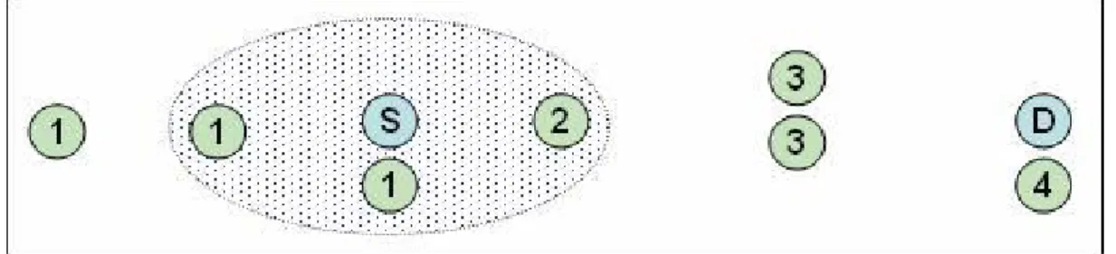
Figure 11 shows a simple topology that depicts all kinds of situations for forwarders. The light-blue nodes marked with “S” or “D” stand for the source and the destination nodes, respectively. Other nodes marked with different numbers represent different types of forwarders. FloodingRD in a forwarding machine analyzes incoming packets and messages during a unit period (currently, the unit period is set to one second) to decide which type of forwarders it is. Note that a FloodingRD may play different types of forwarders for different connections that have different source and destination nodes, individually. As such, a forwarder is able to apply reasonable extra forwarded delays to packets that to be forwarded based on which forwarder type it is for a connection.
Figure 11. A simple topology to show different types of forwarders
Type-1 nodes represent forwarders that are in the direction opposite to the destination node. There is a common feature among these nodes: the rate of the successful packet forwarding is less than other types of nodes. On these nodes, retxQueue would be blocked and therefore reduce the waste of bandwidth. More bandwidth can be further saved by extending FW_FIXED_DELAY to aggravate the blocking of retxQueue. Rather than cancel all transmissions on these forwarders, this method consumes little bandwidth but recovers regular functionality more quickly.
A type-2 node stands for forwarders who should not apply any extra forward delay since the destination node is far away from it, and there is no other forwarder nearby.
Type-3 forwarders can notice the existence of each other by receiving duplicate forwarded packets. If another nearby forwarder exists, these adjacent forwarders begin competing the forwarding of a packet. Firstly, each one selects FW_RANDOM_DELAY in a predefined range. Then, the forwarder with smallest random delay will cancel the forwarding of others and become the winner who takes
Type-4 nodes are the nodes that are next to the destination node. A type-4 node has to apply the fixed delay to wait for the acknowledgements of the forwarding packets. If it detects that the fixed delay is not long enough, the delay time should be extended.
Because determining the forwarder type of a node must collect the required information during a unit period, the reaction time is not as instant as the former one. Besides, since the measurement of those RTTs require the transmissions of data packets and their acknowledgements, Auto Tuning mechanism may not work well when the network traffic load is low. However, under this situation the problem of redundant packets is not severe.
4.5.4
Results
We have shown how Auto Tuning changes parameter settings to adapt to the network conditions in the experiment results shown in section 4.2.3. The results presented in this section are the integral improvements of the performances, such as greedy UDP throughputs, TCP throughputs, and latencies.
Table 6 lists FloodingRD with different configurations used in these experiments. The RF daemon is provided as a contrast, which enables all functionalities with fixed parameter settings. The AT_RTT daemon modifies RF to determine the waiting period for an ACK (by the parameter RQ_RETX_TIMEOUT) dynamically. AT_FFD determines the value of FW_FIXED_DELAY by the number of ACK packets from the destination node. The AT_FRD daemon extends the value of FW_RANDOM_DELAY by detecting the existence of other forwarders aside it. The AT daemon enables all functionalities described above.
Symbol Describe
RF Enable forward-random delay and retransmission AT_RTT Decide the waiting period for an ACK dynamically AT_FFD Decide the value of FW_FIXED_DELAY automatically AT_FRD Decide the value of FW_RANDOM_DELAY automatically AT Enable all Auto Tuning functions
Table 6. Types of FloodingRD
Because Auto Tuning can change the value of RQ_RETX_TIMEOUT to fit the requirements of different network environments, the value of this parameter is reduced to be 40 instead of the original value 80. However, this value is similar to that used by AT_RTT, and the performances of daemon AT_RTT are therefore similar to those of daemon RF.
Figure 12 presents the average throughput for greedy UDP connections in a chain network with 2 nodes to 5 nodes. In 2-node cases, only the AT_RTT and AT daemons raise the throughput performance. Because the extra forward delay mechanism only takes place on forwarders, it can not provide any improvements when no forwarders exist in 2-node cases. Generally, the reduction of the values for the FW_RANDOM_DELAY parameter can improve the average throughput more than that for the RW_FIXED_DELAY parameter. Besides, the AT daemon can double the average throughput in 3-node cases. These improvements become less and less significant while the number of nodes increases.
Auto Tuning, the RTT time will be decreased by taking off the extra unnecessary forward delay overhead, and the retransmission timeouts can therefore be reduced further and raises the UDP throughputs.
UDP Throughput
0.00 50.00 100.00 150.00 200.00 250.00 300.00 350.00 400.00 450.00 2 3 4 5 Number of Nodes U D P T hr ou gh pu t ( K by te /s ) RF AT_RTT AT_FFD AT_FRD ATFigure 12. Average UDP throughput to compare functions of Auto Tuning
UDP Throughput
0.00 50.00 100.00 150.00 200.00 250.00 300.00 350.00 400.00 450.00 2 3 4 5 Number of Nodes U D P T hr ou gh pu t ( K by te /s ) RF AT_RTT AT_FFD AT_FRD ATFigure 13. Average Latency under one-way greedy UDP
Figure 13 presents the measured latencies in the same experiment settings with Figure 12. These results prove that Auto Tuning functionalities indeed reduce the latencies. On the other hand, the results also provide an evidence of the relationship
between latency and UDP throughput in our scheme. We can observe that the daemon, which can reduce latency, can raise UDP throughput as well.
The average RTT time is measured on the source node. Figure 14 organizes these data in the same experiment settings and provides another evidence of the relationship between latency and UDP throughput.
Average RTT Time
0.00 10.00 20.00 30.00 40.00 50.00 2 3 4 5 Number of Nodes A ve ra ge R T T T im e (m s) RF AT_RTT AT_FFD AT_FRD ATFigure 14. Average RTT time at the source under one-way greedy UDP
Figure 15 illustrates the average TCP throughputs in the same topology. Unlike UDP, the throughput of TCP is limited by the protocol design rather than our retransmission scheme. Therefore, the reduction of latencies influences TCP performance slightly.
Chapter 5 Implementation
Our system is built on Linux platform. Chapter 3 has described the architecture of our scheme. The related issues and the existing technologies used for implementation are given here.
5.1
Packet Filter
There are lots of existent net filter technologies for the packet redirection. “Netfilter” in Linux and “divert socket” in FreeBSD are both famous tools to intercept the desired packets. Generally, a net filter is used to build the internet firewalls or to apply the translation of network address and port (NAT). We used netfilter and related technologies such as iptables and libipq library to intercept the packets passed by the kernel.
Netfilter and iptables are building blocks of a framework inside the Linux 2.4.x and 2.6.x kernel. Netfilter can be considered as a set of hooks inside the Linux kernel that allows the kernel modules to register callback functions with the network stack. Iptables provides a set of commands as an interface between user and netfilter. Users can use iptables commands to tell netfilter what to do with the passing packets. Netfilter may buffer packet a special queue, and libipq is a development library that
The following example is the configuration that we used on Linux for the field trials.
iptables -N flood_buffer
iptables -A OUTPUT -d 1.0.1.0/24 -j flood_buffer iptables -A flood_buffer -d ! 1.0.1.n -j QUEUE
Our experiments took the subnet 1.0.1 (netmask 0xffffff00) as the original network domain and added a new subnet 1.0.2 for FloodingRD. The number “n” is an identified id of a host. The first rule defines a new queue named flood_buffer. The second rule lets all normal unicast packets be placed in flood_buffer queue. Finally, the last rule inspects the packets in flooding_buffer queue. If a packet is for the local host, it will be passed through to avoid infinite loops. Other packets will be collected into a predefined queue provided by Netfilter, and FloodingRD can receive packets from this queue by the functions defined in libipq library.
To make a NIC receive or send packets with two different network subnets, a common technology, “IP aliasing”, is used to configure the NIC with two IP addresses. Typical uses of IP aliasing are virtual hosting of Web and FTP servers and reorganizing servers without having to update any other machines. The following commands can make a NIC simultaneously receive packets from 1.0.1.x and 1.0.2.x.
ifconfig wlan0 inet 1.0.1.n netmask 0xffffff00 ifconfig wlan0:0 inet 1.0.2.n netmask 0xffffff00
5.2
Limitations of Current NICs
To be backward with earlier 802.11 products, the broadcast transmission rate is fixed at 2Mbps rather than 11Mbps for unicast packets. This feature limits the maximum throughput of our scheme. To enhance the transmission rate of broadcasts,
some modifications for the drivers of NICs are required. Fortunately, there are still some NICs that provide the ability for configuring the transmission rate for broadcast. Thanks to the existence of this kind of NICs, we can save efforts to modify the drivers.
Chapter 6 Performance Evaluation
Functionalities of FloodingRD and their efficacy have been demonstrated in Chapter 4. However, these experiment results are generally for a specific purpose. What we want to present in this chapter are the integral performances, such as the maximum throughput, the latency and the packet loss rate for different traffic types.
At the beginning, an introduction of various performance metrics is given. Section 6.2 briefs the environment of these experiments. Section 6.3 shows the practical results. Because the circumstances of large scale networks are hard to get by real experiments, simulation is used to help us observe the operation of our scheme in large networks. The related results are given in section 6.4. At the end of the simulation section, there is an evidence for the ability of FloodingRD to get adapt to high mobility environments
6.1
Performance Metrics
While developing a routing protocol, how can we judge it is good or bad? What are the important features of a good routing protocol? Here we define some performance metrics by that we can quantify and measure the efficiency of a routing daemon. These metrics include the average throughput, the packet loss rate, the end-to-end latency as well as the redundancy degree, etc.
6.1.1
Throughput
write these records into a log file. By analyzing these log files, we can get the average throughput easily.
6.1.2
End-to-End Latency
Latency is defined as the period from the time a packet is sent out from the source and the time it is received by the destination. A short latency is required by video and audio communication services. The stg/rtg programs, a pair of traffic generators, record the delay time of each received packet. However, this mechanism needs to synchronize the system time on the source node and the destination node. Even after correcting the system time on hosts by time services, the difference between each host is still too large to provide accurate latency time.
We exchange the role of the two end hosts and record packet latencies twice. By averaging these two recorded values, the latency can be measured precisely.
6.1.3
Packet Loss Rate
Each packet passed by FloodingRD is marked with a sequence number. This number can be used to calculate the packet loss rate:
6.1.4
Redundancy Degree
The redundancy degree is defined as follow:
($packet_count - $valid_packet) * 100 / $packet_count) The $valid_packet is defined in the last section. The $packet_count is the total number of received packets. Under an unfavorable condition, the redundancy degree may exceed 100%.
6.1.5
End-to-End Re-ordering Degree
We record the end-to-end re-ordering degree by the processes as follow:
if($c_snum < $snum ){ $c_snum = $snum; }else{
$difference = $c_snum - $snum; }
The $snum is the sequence number of each received packet, while the $c_snum stands for the current accepted sequence number. The $c_snum is updated by an incoming packet that has a larger sequence number. Once a valid packet with a less sequence number arrives, the difference between the $c_snum and the $snum will be recorded.
After collecting the difference values, the re-ordering degree can be calculated as follow:
The $valid_packet is the total number of valid packets.
6.1.6
Mobility
Unlike average throughput or end-to-end redundancy degree, mobility is hard to be quantified. However, by analyzing the snapshot of TCP throughput under high speed environment, we can still prove that FloodingRD has the ability to overcome the topology which changes rapidly and frequently.
Section 6.4.4 demonstrates the TCP performance reached by FloodingRD under a high speed environment.
6.2
Experiment Environment
6.2.1
Hardware and Software
Table 7 lists hardware and software used in real experiments and simulations. These 802.11b NICs can be configured to broadcast packets at transmission rate of 11 Mbps. Because the performance results about large scale topology are hard to get by practical experiments, we therefore use NCTUns network simulator [22] to observe the behavior of our protocol in large networks.
packaged with NCTUns) (2) ttcp
Routing Daemon FloodingRD Simulator NCTUns 2.0
Table 7. The hardware and software used in experiments
6.2.2
Traffic Type
We chose one-way greedy UDP, two-way greedy UDP, and greedy TCP traffics to validate the performance of FloodingRD. Because the TCP traffic is naturally a kind of two-way traffic, it is not necessary to test our daemon with two TCP traffics.
The two-way UDP traffic type lets two nodes in the network send packets to each other. By observing the behavior of the two-way UDP, we can look into the traffic condition of the TCP links. Because TCP is a sensitive and complicated protocol, to detect error with the TCP traffic is a hard work. If some mistakes damage the two-way UDP traffic, we can conclude why the TCP traffic can’t work in the same environment and then try to solve the problem.
6.2.3
FloodingRD Configuration
The parameter settings of FloodingRD are almost the same with Table 5. The only difference is that the RQ_RETX_TIMEOUT is changed to 40. Because Auto Tuning can modify this parameter according to the circumstance of network environment, we need not choose a large waiting time that damages the UDP performance.
Besides, for observing how the performance is influenced by different functionality, there are lots of FloodingRD with different configuration used in
various experiments and simulations. Table 8 lists the details and differences among them.
The first column of Table 8 is the name of each FloodingRD, and the functionalities are listed at the top of the table. “FFD” means the value of FW_FIXED_DELAY, while “FRD” means the value of FW_RANDOM_DELAY. “Retx Times” is the configured maximum retransmission times. Functionality “AT_RTT” enables a daemon with the ability to change retransmission waiting time dynamically. Function “AT_FFD” and “AT_FRD” adjust the value of FW_FIXED_DELAY and FW_RANDOM_DELAY respectively.
Functionalities Name
FFD Retx Times FRD AT_RTT AT_FFD AT_FRD Basic 8 0 0 R1 8 1 0 R2 8 2 0 F 8 0 40 RF 8 1 40 AT_RTT 8 1 40 On AT_FFD 8 1 40 On AT_FRD 8 1 40 On AT 8 1 40 On On On
Table 8. FloodingRD with different configuration used in experiments
The Basic daemon that has no additional functionality but the overhead of forward-fixed delay is provided as a contrast. The daemon R1 and R2 was used to prove how retransmission protects TCP traffic in section 4.2.3, while the daemon F