Journal of Magnetism and Magnetic Materials 209 (2000) 220} 223
Geometric shape dependence of coercivity for patterned
magnetic thin "lms
Te-Ho Wu
!,*, J.C. Wu", C.S. Wu", Bing-Mau Chen#, Han-Ping D. Shieh#
!Department of Humanities and Sciences, National Yunlin University of Science and Technology, Touliu 640, Taiwan, ROC"Department of Physics, National Changhua University of Education, Changhua 500, Taiwan, ROC #Institute of Electro-Optic Engineering, National Chiao-tung University, Hsinchu 300, Taiwan, ROC
Abstract
The micro-strips with patterned magnetic domains using electron beam lithography have been made to study the geometric shape dependence of coercivity. The size of the micro-strip is 10lm]30 lm with 0.5 lm periods hole arrays pattern. Arrays with di!erent types of geometry, such as square-, circle-, and ellipse-shapes have been made. Amorphous rear-earth transition-metal (RE-TM) thin "lms with magnetic perpendicular anisotropy were deposited on the micro-strips. The extraordinary Hall e!ect has been employed to measure the hysteresis loop and the coercivity of the sample. We have found that for the same deposited material, the magnitude of coercivity for various shapes are dissimilar. For example, the coercivity of the ellipse-shaped hole arrays is much larger than the coercivity of the square-shaped hole arrays. In addition, we observed that the coercivity of the patterned sites was larger than the sites without patterns for RE-dominated compounds and the coercivity of the patterned sites was smaller than the sites without patterns for TM-dominated compounds. The magnetic moments canting between RE and TM subnetworks will be used to explain the observed phenomena. ( 2000 Elsevier Science B.V. All rights reserved.
Keywords: Coercivity; E-beam lithography; Micro-structure; Shaped-dependence; Canting
1. Introduction
A major concern usually encountered in descriptions of the magneto-optical write and erase processes is the coercivity of the thin "lm material. Technically, the co-ercivity H# is de"ned as for a hysteresis loop as the value of applied "eld at which the net magnetization becomes zero. Coercivity, however, is an ill-de"ned concept which may be useful in the phenomenology of bulk reversal, but its relevance to the phenomena occurring on the spatial and temporal scales of thermomagnetic recording must be seriously questioned. To begin with, there is the prob-lem of distinguishing the nucleation coercivity from the coercivity of wall motion. Then there is the question of speed and uniformity of motion as the wall expands beyond the site of its origination. Finally one must
ad-* Corresponding author. Tel.: 886-5-534-2601 ext. 3166; fax:
886-5342601 ext. 3166.
E-mail address: wuth@#ame.yuntech.edu.tw (T.-H. Wu)
dress issues of stability and erasability, which are inti-mately related to coercivity, in a framework wide enough to allow the consideration of local instabilities and par-tial erasure. It is fair to say that the existing theories of coercivity [1}3] are generally incapable of handling the problems associated with magneto-optical recording and erasure. We have shown in previous publications that the patterned magnetic "lms possess di!erent coercivity compared with "lms without patterns [4,5]. In addition, the various shapes of the patterned hole arrays also displayed di!erent coercivity. In our view, the direct vehicle for conducting the coercivity investigations is via experimental methods. Thus, it inspired us to use micro-strip structures with di!erent geometric hole arrays to explore the origins of coercivity.
2. The experimental methodology
Several magnetic micro-strips with various geometric hole arrays have been made. The fabrication procedures 0304-8853/00/$ - see front matter ( 2000 Elsevier Science B.V. All rights reserved.
Fig. 1. Cross-sectional view of fabricated layer structure: sili-con/SiN(200 nm)/DyFeCo(50 nm)/SiN(30 nm) in the holes and silicon/SiN(200 nm)/Au(30 nm)/DyFeCo(50 nm)/SiN(30 nm) otherwise on the gold ridges.
of these magnetic devices with arti"cial pinning sites are described as follows. A 10lm wide gold strip with vari-ous geometric holes arrays were "rst fabricated on a Si3N4-coated silicon substrate by a lift-o! process using electron beam lithography. The thickness of the gold strips is 30 nm. The square-, circle-, and ellipse-shaped hole arrays with a lateral dimension of 0.5lm and a periodicity of 1lm were produced along the gold strips. The elliptical holes have 1.0lm on long axis and 0.5lm along short axis. A second step of electron beam lithography was employed for making a long trench in the electron resist, in which the trench covered the gold strip. This process is necessary for the further lift-o! procedure, after the magnetic "lm deposition, to take away the area without patterns to make the magnetic micro-strip. Trenches for the current and voltage leads were made at this time as well. The MO active layer DyFeCo with a thickness of 50 nm was then DC mag-netron co-sputtered onto the pre-formatted pinning patterns, and a 30 nm thickness of SiN layer was subsequently deposited to protect the MO layer. In order to make the magnetic micro-strip a second lift-o! process was performed to remove the area without any patterns. The "nal layer structures is shown in Fig. 1. The mag-netic micro-strip with arti"cial pinning sites for the square-shaped hole array image taken from SEM is dis-played in Fig. 2. An external magnetic "eld perpendicular to the "lm plane is applied and the extraordinary Hall e!ect has been employed to measure the hysteresis loop and the coercivity.
3. Results and discussions
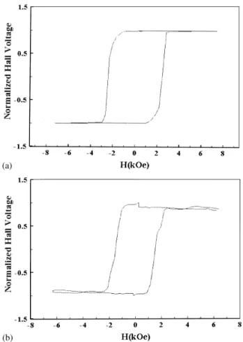
Fig. 3 shows two V}H (Hall voltage versus ex-ternal applied "eld) hysteresis loops for "lm Dy26.9(Fe80Co20)73.1. The "lm without pattern is shown
Fig. 2. An image taken from SEM; the magnetic micro-strip with arti"cial pinning sites for the square-shaped hole array image taken from SEM.
Fig. 3. Shows two V}H hysteresis measurements for sample Dy26.9(Fe80Co20)73.1: (a) the "lm without patterned hole ar-rays; (b) ellipse-shaped pattern.
in Fig. 3(a) and the "lm with ellipse-shaped pattern (with long axis 1.0lm and short axis 0.5 lm) is displayed in Fig. 3(b). The shape of the hysteresis loops (not shown) of the "lm with square- and circle-shaped are similar to Fig. 3(b). Table 1 summaries coercivity values versus di!erent geometric shapes for various compounds of
Table 1
Coercivity values versus di!erent geometric shapes for various compounds of Dyx(FeCo)1~x
Sample Dy26.9(Fe80Co20)73.1 Dy21.0(Fe80Co20)79.0 Dy22.3(Fe80Co20)77.3
RE-rich TM-rich TM-rich
Shape Ellipse Circle Square No pattern Ellipse Circle Square No pattern Ellipse Square No pattern
H# (kOe) 16.78 14.77 12.55 6.88 1.37 1.53 0.23 2.51 3.54 3.51 5.5
Dyx(FeCo)1~x. We found that coercivity was enhanced the most for a RE-rich "lm with ellipse-shaped patterns. Among various patterned geometric shapes, the magni-tude of coercivity in sequence is H# (ellipse)'H# (circle)'H# (square); and the coercivity for a "lm with-out any pattern gave the smallest value. In addition, the hysteresis loop for thin "lm without pattern shows good squareness (see Fig. 3(a)), while for the patterned micro-strips, the scheme of hysteresis loops are quite di!erent; curvatures on both top and bottom parts of the loop have been observed, as shown in Fig. 3(b). The hysteresis behaviors of Fig. 3(b) is described subsequently. When the applied "eld was increased positively the Hall signal decreased "rst (points o to a), then increased linearly until the applied "eld ended (points a to b). Special attention should be paid when the applied "eld is reversed; the Hall signal increases and reaches to a maximum value (points o to c), then decreases monotonously until the magne-tization reversal process begins (points c to d). The rea-sons for the aforementioned phenomena were due to three facts. The "rst cause was because of the presence of canting between RE and TM sub magnetic components [6]; the second reason was that the contributed EHE signal mainly comes from the TM sub magnetic compo-nent [7]; and the third reason was due to the existence of magnetic moments perpendicular to the side-wall around the hole arrays. A detailed theoretical model will be published on another paper.
The magnetic moment canting behavior also contri-buted to the coercivity sequence of H# (ellipse)'H# (circle)'H# (square)'H# (without pattern). The reason for the patterned thin "lms possessing larger coercivity is due to the magnetization reversal processes being im-peded by two coercive forces, one from the nucleation coercive force, and the other from the anisotropy coercive force. Due to the large canting angle, the an-isotropy coercive force will impede the magnetization reversal process, thus increasing the coercivity value. This explains that the coercivity of the patterned "lms is larger than the "lm without pattern. Moreover, the rea-son for the ellipse-shaped pattern coercivity being larger than the circle- and square-shaped is as follows. For ellipse-shaped geometry, when the applied "eld pushes the canting angle on the short axis (the same radius as
Fig. 4. Shows two V}H hysteresis measurements for sample Dy21.0(Fe80Co20)79.0: (a) the "lm without patterned hole array; (b) ellipse-shaped pattern.
that of the circle-shaped hole) reaching the maximum angleh#, the canting angle of the long axis still has not reachedh#. Thus, more external applied "eld is needed to reverse the magnetic moments to the other direction compared to the circle- and square-shaped patterns. As a result, the coercivity of the ellipse shape is larger than the circle and square shapes.
Fig. 4 shows two V}H hysteresis measurements for sample Dy21.0(Fe80Co20)79.0. The "lm without pat-terned hole arrays is shown in Fig. 4(a) and the "lm with ellipse-shaped pattern (with long axis 1.0lm and short 222 T.-H. Wu et al. / Journal of Magnetism and Magnetic Materials 209 (2000) 220}223
axis 0.5lm) is displayed in Fig. 4(b). For TM-rich sam-ples, however, the situations are much di!erent from the RE-rich sample. As summarized in Table 1, the coercivity for a "lm without any pattern gives the largest value for samples Dy21.0(Fe80Co20)79.0 and Dy22.3(Fe80Co20)77.7. In addition, "lm with compound near compensation composition shows that the ellipse-shaped pattern has comparable coercivity with the square-shaped pattern. Moreover, the schemes of hysteresis loops, unlike the Dy-rich thin "lm, show better #atness on both top and bottom curves. These results could also be explained by the previously mentioned three facts. We conjecture that the reason that the hysteresis loops shows better #atness might be due to the exchange coupling strength and anisotropy energy, for Dy21.0(Fe80Co20)79.0 sample is larger compared with Dy-rich sample [8]. As a result, the canting behavior of side-wall moments of the hole is not apparent. Thus, the hysteresis loops show #atness.
4. Concluding remarks
We have made a series of RE}TM amorphous micro-strip samples to study the relationships among di!erent geometric shapes, compounds of "lm, and coercivity. We have found that, for RE-rich samples, among various geometric patterned shapes the magnitude of coercivity in sequence is H# (ellipse)'H# (circle)'H# (square)'
H# (without pattern). For TM-rich samples, however, the
situations are quite di!erent. The coercivity for a "lm without any pattern gives the largest value and "lm with compound near compensation composition shows that the patterned ellipse-shape has comparable coercivity with the patterned square-shape. All the aforementioned phenomena can be explained by the magnetic moment canting behaviors between RE and TM subnetworks.
Acknowledgements
This work is supported by the National Science Council, the Republic of China, under contract No. NSC 88-2112-M-224-001.
References
[1] R. Friedberg, D.I. Paul, Phys. Rev. Lett. 34 (1975) 1234. [2] D.I. Paul, J. Appl. Phys. 53 (1982) 2362.
[3] A. Sukiennicki, E. Della Torre, J. Appl. Phys. 55 (1984) 3739. [4] Te-Ho Wu, J.C. Wu, Bing-Mau Chen, Han-Ping D. Shieh,
J. Appl. Phys. 85 (8) (1999) 5980.
[5] Te-Ho Wu, J.C. Wu, Bing-Mau Chen, Han-Ping D. Shieh, J. Magn. Magn. Mater. 202 (1999) 62.
[6] S. Rinaldi, L. Pareti, J. Appl. Phys. 50 (1979) 7719. [7] Te-Ho Wu, Hong Fu, R.A. Hajjar, T. Suzuki, M.
Man-suripur, J. Appl. Phys. 73 (3) (1993) 1368.
[8] Wein-Kuen Hwang, Te-Ho, Han-Ping D. Shieh, J. Appl. Phys. 81 (11) (1997) 7437.