國 立 交 通 大 學
電 機 與 控 制 工 程 學 系
碩 士 論 文
以 CAM 為基礎之樣式累加向量法
在車牌字元辨識系統之應用
A CAM-Based License Plate Character Recognition
System Using the Pattern Accumulated Vector Method
研 究 生:張 仲 賢
指導教授:陳 永 平 教授
以 CAM 為基礎之樣式累加向量法
在車牌字元辨識系統之應用
A CAM-Based License Plate Character Recognition
System Using the Pattern Accumulated Vector Method
研 究 生:張仲賢 Student:Chung-Hsien Chang
指導教授:陳永平 教授 Advisor:Prof. Yon-Ping Chen
國 立 交 通 大 學
電機與控制工程學系
碩士論文
A Thesis
Submitted to Department of Electrical and Control Engineering
College of Electrical and Computer Engineering
National Chiao Tung University
In Partial Fulfillment of the Requirements
For the degree of Master
In
Electrical and Control Engineering
June 2006
Hsinchu, Taiwan, Republic of China
中華民國九十五年六月
以 CAM 為基礎之樣式累加向量法
在車牌字元辨識系統之應用
學生:張 仲 賢
指導教授:陳永平 教授
國立交通大學電機與控制工程學系
摘 要
車牌字元辨識系統,是交通執法系統、電子道路收費系統等眾多
交通相關應用領域上的關鍵技術。然而,絕大多數已經研發完成的車
牌辨識系統由於採用相當複雜的演算法,而不得不藉由電腦輔助環境
來運作。
本 論 文 將 車 牌 字 元 辨 識 系 統 建 構 於 DSP 實 驗 板 上 ( 型 號 :
EP20K1500EBC652-1X),旨在驗證完全交由硬體系統來獨立完成之
可能性。該系統不僅使用內容可定址記憶體來取代傳統記憶體,更採
取所謂的樣式累加向量法來進行車牌字元辨識。透過模擬實驗,該系
統不但可達到 99.78% 之辨識率,所需時間也比使用傳統記憶體的對
照組還要短。這證明了車牌字元辨識系統在硬體化上的可行性。
A CAM-Based License Plate Character
Recognition System Using the Pattern
Accumulated Vector Method
Student: Chung-Hsien Chang
Advisor: Prof. Yon-Ping Chen
Department of Electrical and Control Engineering
National Chiao Tung University
ABSTRACT
License plate character recognition system becomes the key to many traffic related applications such as the traffic enforcement systems and the electronic toll-collection systems. However, most of the developed license plate recognition systems are PC-based due to the use of complicated algorithms.
This thesis implements the license plate character recognition on the DSP board (SN: EP20K1500EBC652-1X) to verify the potential of a hardware system other than PC-based. The system adopts a specific storage called the Content Addressable Memories to replace the common RAM and recognizes the license plate characters by the so-called Pattern Accumulated Vector method. Through series of simulations and experiments, the recognition reaches a rate of 99.78% and is faster than the RAM-based system. This confirms that the proposed system has potential and is feasible in the future.
Acknowledgement
本篇研究論文能夠順利完成,首先必須感謝指導教授 陳永平老師於 作者在大學時進修專題到碩士修業等這三年多來孜孜不倦的教誨。使作者 在研究方面、求學態度與待人處事上有所啟迪,在此謹向老師至上最高的 謝意和敬意。同時,也感謝口試委員 林進燈教授與 林昇甫教授對於本 篇論文所提出的寶貴意見以及改進之處,使本論文得以更趨完備。 此外,感謝實驗室倪豐洲學長、同學、學弟們對於學業上的討論及生 活上的照顧。也要感謝陪伴作者度過研究所與大學階段的所有好友們,包 括守裕、建成、炯廷、孟軒、宏銘、山田真弘、精佑、丞師 等,與交大 動畫社的夥伴們。對於辛苦養育、教育作者二十餘載的父母更是難以感謝 二字表達由衷的感激。 僅以此篇論文獻給所有關心、照顧我的人。 張仲賢 2006.6.17Contents
Chinese Abstract
i
English Abstract
ii
Acknowledgment iii
Contents iv
List of Figures
vi
List of Tables
viii
Terminologies ix
Chapter 1 Introduction
....………...……….……. 11.1 Motivations .…………..………...……….……. 1
1.2 Problem Statements .…………..………...………. 2
1.3 Flow Chart of the Proposed System …….………... 6
1.4 Contents Organization ………..…………...………... 7
Chapter 2 Design of Content Addressable Memory
..…….…...….. 82.1 Motivation …..………..………... 8
2.2 Fundamentals .………..………... 10
2.2.1 Basic Block Diagram ………... 11
2.2.2 Time Efficiency ………... 12
2.3 Architecture of CAM …………..……..…….……… 15
2.3.1 Specific Use of the Mask Register …...………....……..…..………… 17
2.3.2 The Word Select Register versus the Mask Register ………... 18
2.4 VHDL Design of CAM …………..……..….……… 21
Chapter 3 The PAV Method for Character Recognition
..……….. 303.1 Motivation …….………. 31
3.2 Pattern Block………...………... 33
3.3 Fundamentals of the PAV Method ……….……… 36
3.4 Recursive Selection of the Principal Pattern Blocks…... 39
3.4.1 Threshold Decision of the Criteria ………....……..……...…… 43
3.5 The Basic PAV Method………... 46
3.6 The Improved PAV Method………... 55
Chapter 4 Simulations and Experiment Results
………....……….. 674.1 Database ………..…..…………. 68
4.2 The Recognition Result of the Basic PAV Method ……..…………. 69
4.3 The Recognition Result of the Improved PAV Method ………. 70
4.4 The Recognition Rate Comparison ………...…. 71
4.5 The Processing Time Comparison ………….………...…. 73
Chapter 5 Conclusions
………..………..……….……….. 75List of Figures
Figure 1-1 The typical PC-based LPR system ……...… 5
Figure 1-2 The typical portable DSP-based LPR system ….………..……...… 5
Figure 1-3 Flow chart of the proposed system …………..………..…...…6
Figure 2-1 The basic block diagram of CAM……… 11
Figure 2-2 The typical architecture of CAM …...……….. 15
Figure 2-3 The coordination between the mask register and the word select register ……...………...………... 19
Figure 2-4 Pin assignment of the 9-bits 512-words CAM ………..….. 24
Figure 2-5 The function test of the proposed CAM ………..….... 25
Figure 2-6 The flow chart of the binarization test ………..…..….... 25
Figure 2-7 CAM function test – Store the image “A” ……….……….. 27
Figure 2-8 CAM function test – Search the pattern …….……….. 27
Figure 2-9 CAM function test – End of multiple-matched addresses sequence ………... 28
Figure 2-10 CAM function test – Write a new image “B” …..……….... 28
Figure 3-1 The pattern blocks in the top three rows of the template “2” ….…….. 35
Figure 3-2 The pattern blocks combination of the template “2” ….……..…..….. 35
Figure 3-3 The binary standard templates …..……….……... 38
Figure 3-4 The recursive selection of the principal pattern blocks …..………... 42
Figure 3-5 The max recognition rate distribution of x selected pattern blocks …. 47 Figure 3-6 The max recognition rate distribution in 20 selected pattern blocks ... 47
Figure 3-7 The PAV of templates “0” to “3” ………....…….. 51
Figure 3-8 The PAV of templates “4” to “7” ………....……….... 51
Figure 3-10 The PAV of templates “C” to “F” ………....……….... 52
Figure 3-11 The PAV of templates “G” to “J” ………...……….... 53
Figure 3-12 The PAV of templates “K” to “N” ………....……….... 53
Figure 3-13 The PAV of templates “O” to “R” ………....……….... 54
Figure 3-14 The PAV of templates “S” to “V” ………....……….... 54
Figure 3-15 The PAV of templates “W” to “Z” ………...……….... 55
Figure 3-16 The max recognition rate distribution of x improved pattern blocks ... 57
Figure 3-17 The max recognition rate distribution in 20 improved pattern blocks ………... 58
Figure 3-18 The improved PAV of templates “0” to “3” ………..………..……... 61
Figure 3-19 The improved PAV of templates “4” to “7” ………..………..……... 61
Figure 3-20 The improved PAV of templates “8” to “B” …..…..………..……... 62
Figure 3-21 The improved PAV of templates “C” to “F” ……...………..……... 62
Figure 3-22 The improved PAV of templates “G” to “J” ………..………..……... 63
Figure 3-23 The improved PAV of templates “K” to “N” .….…..………..……... 63
Figure 3-24 The improved PAV of templates “O” to “R” …..…..………..……... 64
Figure 3-25 The improved PAV of templates “S” to “V” …..…..………..……... 64
Figure 3-26 The improved PAV of templates “W” to “Z” ….…..………..……... 65
Figure 3-27 The blocks overlap storage way of an image to a CAM …....……….. 66
Figure 4-1 Some of the 1800 input binary images ………..…..…..….. 68
Figure 4-2 The recognized details of different methods ………..…..…..….. 72
List of Tables
Table 2-1 Sample data in the memory.………...………. 12 Table 2-2 The compilation results of 6 candidates of CAM ….…..…….………. 22 Table 3-1 Different types of pattern block ……….…..…….………. 33 Table 3-2 The matching results of 512 patterns with 36 templates ……..………. 38 Table 3-3 The distribution of the amount of successful recognition cases ……... 45 Table 3-4 12 principal pattern blocks for 36 standard templates ………... 49 Table 3-5 The distribution of the amount of recognitions for improveddatabase……….. 56 Table 3-6 16 improved principal pattern blocks for templates database ………... 59 Table 4-1 The recognition results of the basic PAV method ………..……... 69 Table 4-2 The statistical recognition results of the basic PAV method ………... 69 Table 4-3 The recognition results of the improved PAV method ………...……... 70 Table 4-4 The statistical recognition results of the improved PAV method …... 70 Table 4-5 The failures in the improved PAV method ……….……... 71 Table 4-6 The recognition rates of three different recognition methods ….……... 72 Table 4-7 The average processing time of CAM-based and RAM-based
Terminologies
(a1a2a3) : The serial number of a pattern block, where ai = 0, 1, 2, …, 7, for i = 1, 2, 3.Bn : The n-th binary template image with dimension h×w.
B : The binary template image with dimension h×w.
dt,n : The Euclidian distance between two pattern accumulated vectors vt and vn.
h : The height of the extracted character image. l : The length of the pattern block.
m : The total number of the principle pattern blocks. n : The order of the binary template image.
(aaa N ) 3 2 1 3 2 1
: The info of the pattern block (a1a2a3) related to all the templates Bn .
Pi : The i-th principal pattern block.
P : The set of the principal pattern blocks { Pi }.
un : The feature vector of Bn .
ut : The feature vector of the test binary image.
vn : The pattern accumulated vector of Bn .
vt : The pattern accumulated vector of the test binary image.
w : The width of the extracted character image.
x : The number of chosen pattern blocks among 512 pattern blocks.
(aaa),n
λ : The coefficient of the pattern block (a1a2a3) to Bn .
(aaa
λ )
3 2
1 : The maximum difference between any two λ(a1a2a3),n.
n i,
Chapter 1
Introduction
1.1 Motivations
During the past two decades, Intelligent Transportation Systems (ITS) has been a worldwide movement of using advanced technology to make our surface transport more efficient, less congested, safer, and less polluting [17]. ITS applications have four typical sensors: acoustic, radar, laser, and machine vision. Among them, machine vision is the most important part to ITS [16]. The first three sensors, acoustic, radar, and laser, are all active type to emit signals and measure the travel time of the reflected signals. An implementation of active sensors must take not only the interference among the same type into account, but also the wide variation in reflection. On the contrary, machine vision is a passive sensor and never cause the potential problems associated with the above active sensors. In addition, it is machine vision that can detect lane markings, traffic signs, and even the license plate of each passing vehicle, without any road infrastructure modifications.
One of the most practical topics in machine vision of ITS is the license plate recognition, which is called LPR for short [4]. LPR systems have been adopted in
many facilities in the recent years, such as the traffic enforcement system and the electronic toll-collection systems, etc. It has been proved that different algorithms utilized in the recognition process would directly affect the recognition rate [8]. Besides, some environmental problems also lower the recognition rate, such as outdoor illumination variety, blur license plate image of a moving vehicle, dirty or inclined license plates, and so on. To handle the kinds of problem, many methods or algorithms have been proposed [4][20]. This thesis will also propose a license plate recognition system based on the technology of Pattern Accumulated Vector method, or the PAV method for short, to deal with the inclined variety and noised situations on the character images. In the further step, this thesis will adopt a specific storage called the Content Addressable Memory, to improve the time efficiency in the character recognition, reduce the power consumption, and finally, achieve the equipment portability.
1.2 Problem Statements
In ITS, LPR systems have become the key to many traffic related applications, such as road traffic monitoring and access control of parking lots. A large number of techniques of license plate recognition have been presented in the past two decades. Several systems have been applied in the practical world; for instance, the
management for a parking lot and highway ETC control, or the monitor for a vehicle entry at some building.
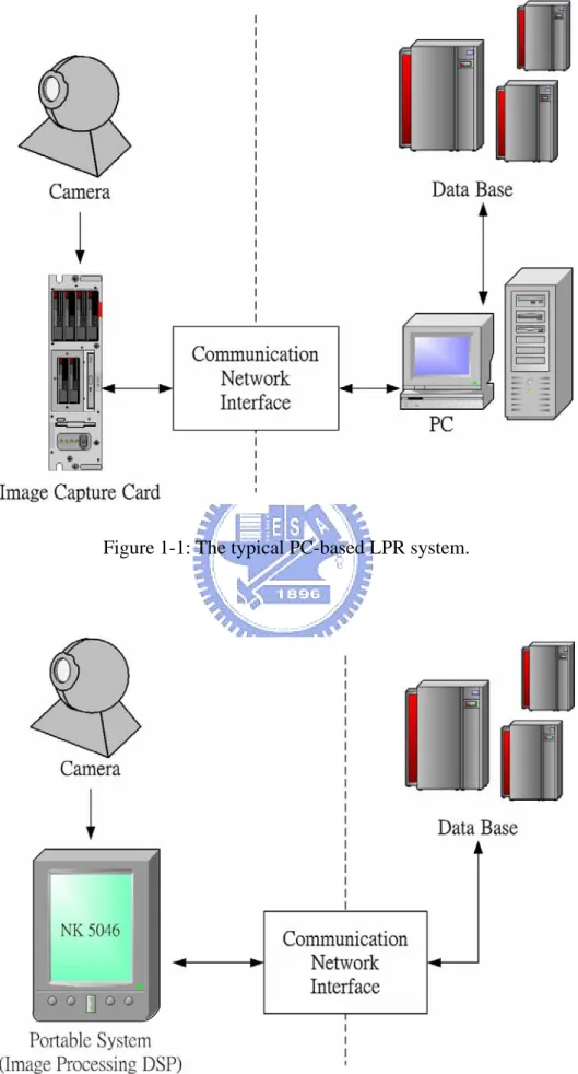
Usually, the recognition algorithm including complicated mathematical operations, such as Neural Fuzzy techniques, is processed under a PC-based architecture. The typical PC-based LPR system is schematically shown in Figure 1-1, which indicates the relationship between each component. A PC-based LPR system acquires images from the sensor same as the process of machine vision, and then transfers these images to the PC through the communication network interface such as ethernet, RS-232, etc. However, there are some other problems along with the PC-based system. For example, the use of the PC makes the LPR system too huge to be portable and the senor area limited and inflexible. In addition, the PC-based LPR system requires high power consumption. In the past two decades, the recognition rate has been obviously raised by a lot of improved algorithms, such as Neural Network [4]. However, the power consumption has also been getting larger and larger. Although the large power consumption doesn’t affect the recognition rate, it would be a problem when taking it into practical consideration.
An effective way to reduce the power consumption is to make the scale of the LPR system smaller and adopt a less complicated image recognition algorithm. Fortunately, in the late two decades the DSP card has been developed and capable for
the problem. An LPR system with an image DSP card will no longer need a PC, and it can also access the database at any time by the communication network. With the DSP architecture, the LPR system can become hardware based and thus totally portable. The typical DSP-based LPR system is shown in Figure 1-2, and the scale of the system has now been reduced successfully.
A PC-based LPR system has a general problem of the power consumption, though it could do complicated operations to obtain a higher result. To solve the problem, a DSP-based LPR system is used and importantly with a high recognition rate.
This thesis will implement the license plate character recognition on the DSP board to verify the potential of a hardware system without the use of PC. The proposed system adopts a specific storage called the Content Addressable Memory, not a common RAM. With the Content Addressable Memory, the time required for the character recognition can be improved. Moreover, to deal with the inclined variety and noised situations on the character images, the proposed system adopts the Pattern Accumulated Vector method, or the PAV method for short, for the license plate character recognition.
1.3 Flow Chart of the Proposed System
It is assumed that the license plate extraction and the character segmentation have been done, and the proposed system focuses on the character recognition. The LPR system is established by the VHDL code, and all of the design is compiled by Altera○R
-Quartus○R
II and Modelsim SE○R
, and is simulated on the development board of EP20K1500EBC652-1X, which is one of the family of DSP device APEX 20KE developed by Altera○R
. The flow chart of the proposed system is shown in Figure 1-3.
1.4 Contents Organizations
The proposed system uses PAV method for the 30×15 pixels character image recognition, and adopts a specific memory called Content Addressable Memory for the storage to replace the common RAM. This thesis is organized as follows. The principle of the Content Addressable Memory is introduced in chapter 2, including the details of the architecture and the implementation procedure.
In chapter 3, an efficient character recognition approach called the Pattern Accumulated Vector method will be proposed. The adopted pattern accumulated vector is the proposed feature vector for the image. Before the establishment of the pattern accumulated vector corresponding to each input image, a suitable set of pattern blocks representing each license plate character template must be found. Therefore, the recursive selection of the principal pattern blocks will also be developed in this chapter.
In chapter 4, the database adopted in the proposed system will be introduced, and then some simulations and experimental results will be shown. Finally, the conclusion about the proposed system and the discussion of the future work are both presented in chapter 5.
Chapter 2
Design of Content Addressable Memory
In this chapter, we focus on two major concepts about Content Addressable Memory, or CAM for short. The first one is the principle of CAM, and the second one is the reason why we use the CAM instead of the common RAM in the proposed LPR system. Then, the details of the VHDL implementation to satisfy the specification for the proposed LPR system will be shown. Finally, an image binarization simulation leading to the summary of the proposed architecture of CAM will be proposed.
2.1 Motivation
Fifty years ago, John von Neumann first proposed the concept of memory and stated that a memory is a storage device for both instructions and data used in computer programming [2]. At the present day computer architecture has been faced with a variety of types of memory when implementing his concept into hardware. The most common type among all storage devices is the random-access memory (RAM), which stores data as an array with indexed data. RAMs are established to have the features that each location can be independently accessed and the access time for each
data in the memories is constant.
In general procedure of searching data stored sequentially in a RAM, the first step is to choose a sequence of successive address corresponding to the memory, and then read out the content from the memory one by one. The searching procedure would stop while the data currently searched is matched [15]. Because of the serial nature of the processing in a RAM, each piece of information should be handled sequentially. Moreover, in a RAM the searching time increases at a rate depending on the memory size, and then it would take multiple clock cycles to complete the above procedure as the memory size increases [12]. As a result, the time consumption would rise up if a more elaborate comparison, such as data correlating or data sorting, is needed during searching.
However, there are more and more data-processing applications which require searching data in RAMs, such as image processing [7], database retrieval [19][26], cache design [21][11], data compression [14][18], and so on. That means the use of searching algorithm with elaborate comparison in a RAM could slow the performance, especially when the size of data on processing is getting larger and larger.
In order to deal with the above drawbacks, this thesis employs the parallel storage method instead of RAM, which is called Content Addressable Memory and will be introduced in next section.
2.2 Fundamentals
In general, the data stored in the RAM must be indexed before further processes, such as data searching or data sorting. It is known that the Content-Addressable Memory, or CAM for short, is based on the RAM technology [5]. Hence, the data stored in the CAM are also indexed similarly. However, different to the RAM with data accessed by their indices, it is not necessary to locate the data in the CAM via their indices, since the CAM considers much more about each data itself rather than its physical index. Besides, the stored data in a RAM are located in sequential, while the CAM searches the stored data in parallel in only one clock cycle and then returns the data’s indices if found [6].
Due to the features of the data content addressability and the parallel capability in data searching, the total required processing time in applications with CAM would be saved. The following will present a simple block diagram and an example table to introduce the above two basic concepts.
2.2.1 Basic Block Diagram
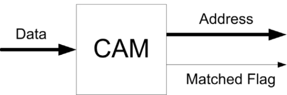
Figure 2-1 shows the basic block diagram of CAM, where the boldface arrows of “Data” and “Address” indicate that their sizes are in bytes. In a general searching procedure, an objective word will be sent into the CAM through the “Data” input. If a word in the CAM matched to the objective word is found, the CAM will release a logic high to the “Matched Flag” and simultaneously send out the corresponding address of the matched word through the “Address” output. Note that the time required to complete the searching procedure is the same no matter where the matched word lies in. In case that there are more than one word matched to the objective word, the CAM, besides releasing a logic high through the “Matched Flag,” will simultaneously send out all the addresses of these matched words sequentially through the “Address” output. In other words, the CAM is purposely designed for parallel searching in words.
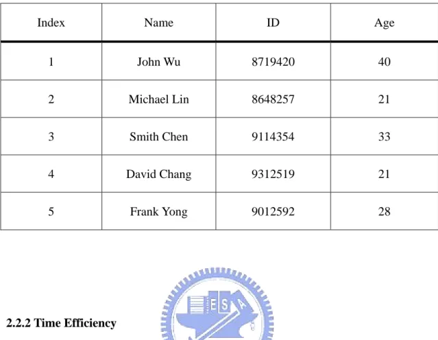
Table 2-1: Sample data in the memory.
Index Name ID Age
1 John Wu 8719420 40 2 Michael Lin 8648257 21 3 Smith Chen 9114354 33 4 David Chang 9312519 21 5 Frank Yong 9012592 28 2.2.2 Time Efficiency
It is known that the search ability of CAM is much better than that of RAM. To clearly describe such advantage of CAM, the searching procedures adopted for CAM and RAM will be first introduced respectively.
For simplicity, let’s consider Table 2-1 as an example, whose data have been stored in a computer’s memory with four sub categories: index, name, ID number, and age. If we want to find out how old David Chang is, we must search the data of David Chang before reading out his age. With CAM, the query word “David Chang” is sent into the “Data” input, and then the CAM simultaneously examines all entries in the table and selects the one that matches the given word, and it finally takes one time
unit to complete the procedure. From the conceptual perspective, “David Chang” can also be considered as the access address which is equivalent to the index “4” to the CAM, and it thus directly access the 4th index to read out the content.
With RAM, the index plays an important role, but unfortunately the content could never be equivalent to it, so the search procedure must be done in sequence. Except the corresponding index of a content in the RAM has been known, the sequential search algorithm for the query word “David Chang” would take the consuming time up to four times longer than the parallel one with the CAM. As the size of the storage data is getting larger, the searching time efficiency with CAM would be more competent than with RAM.
CAM is superior to RAM not only in the above single data matched condition, but also in dealing with the multiple data matched issue. Now let’s consider a special feature of CAM when the multiple data matched problem occurs, and this time we give another question about who is 21 years old, i.e., the query word “21” is sent into the “Data” input to read out the content in the name category, whose corresponding age category is 21. With CAM again, the word is simultaneously examined with all entries in parallel in the table to target the 2nd and 4th indices immediately, i.e., all the matched data and the locations of them are found at the first time, and then the contents, Michael Lin and David Chang, would be read out sequentially. On the other
hand, the search procedure of the query word “21” is done in serial with RAM, so the total number and the locations of matched data must be obtained after the searching through the whole table is accomplished. It means that the location to search of a storage word would badly affect on the searching efficiency of RAM. However, such situation would never happen with CAM.
The parallel-searching feature of CAM would improve the time efficiency, especially for the multiple data matched problem, which always occurs in the image recognition. To speed up the searching process, the use of CAM to the license plate system would be more competitive than the use of RAM.
2.3 Architecture of CAM
The typical architecture of CAM is shown as Figure 2-2 [9][13]. It indicates that the essential components in a CAM include the memory array, the responder and contention logic, the comparand register, the mask register, the word select register, and the output register.
The major function of each component is stated as follows: The memory array provides the storage containing the associative words with contents relative to its address, which is an exceptional feature of the CAM. The comparand register contains the input data, which is called the pattern, to be compared with the words in the memory array. The mask register is to mask off some bit positions in the input pattern while they are treated as “don’t care bits” in several searching commands. For example, if the input pattern is 01001101, but only the least four bits (bit 3 ~ bit 0) are needed for the further search procedure, then the mask register is enabled and set as 11110000. The word select register could generate signals based on input addresses in order to select the locations to be searched of associative words in the memory array. Note that the responder and contention logic would indicate the success or failure after the search operation by setting or resetting the matched flag. Additionally, it is capable for simultaneously receiving all the corresponding matched indices, and resolving the contention of them to send out sequentially, when more than one word in the memory array is matched. As for the output register, it is employed to read out the matched data in the memory array.
To declare more clearly, the comparand register is functioned as a general input buffer, and the mask register covers the useless bits of an input pattern. On the other hand, the word select register chooses the locations of the storage in a CAM, and the
responder and contention logic plays a role of an arbiter. Including the output register, these five components would form the complete architecture of CAM. To make the CAM work correctly, the functions and the relations between the mask register and the word select register must be designed elaborately, which will be described in the follow.
2.3.1 Specific Use of the Mask Register
The provisions for masking the input pattern can be applied in several operations. The most important one may be in the searching on selected categories which are parts of the pattern. Just like Table 2-1, the data in the CAM may be composed of several fields to describe different characteristics, and thus a subset of them can be formed by unmasking the search argument correspondingly.
Besides, another important use of the mask register is the writing of new data into memory locations which happen to be vacant. Because a list of the occupied positions in the memory array usually cannot be maintained, the empty places must be found automatically and intelligently. For this purpose there could be an additional field of vacancy indicator bit in each data which is comparable to the rest data bits. In an empty location the vacancy indicator bit is initially 0, and it is marked 1 when a data is stored. After deletion of the data the bit is again reset to 0.
As a consequence, the blank places can now be found by masking all other bits except the vacancy indicator bit, and it will obtain remarkable performances in saving the capacity of our CAM.
2.3.2 The Word Select Register versus the Mask Register
It has been shown that both the word select register and the mask register search their objects in the same memory array. Here, the way of how they search will be explained. In addition, their searches are designed one after the other, to avoid the possible collision, which will be shown below.
The search form to the pattern would be affected by the mask register, but on the other hand, the search area through whole addresses in the memory array would be set by the word select register. If the possible result of the matched address, which is supposedly output after the effect of the mask register, must be canceled because of the influence of the word select register, the collision in time would come out and make the output signal “unknown”. According to [6], the word select register is purposely designed prior to the mask register. Thus it can avoid the conflict between the two functions of them.
Figure 2-3 is an example to show when the collision condition happens, and how a typical CAM would deal with it. The figure indicates that there are six data already
in the memory array, and the common search operation is adopted. At first, the pattern “00110010” is input and stored in the comparand register, and then the mask register is enabled and set as “00001100” to make the bit 2 and bit 3 “don’t care,” which means the two positions will be ignored in the further processing. In the mean while, the three indices of {000, 001, 010} are also sent into the word select register, denoted as Iws, to enable it and further cover the useless locations in the memory array.
The search operation is going to start. For the first condition, let’s disable the function of the word select register. Then the mask register enables, and it would make the search “0011XX10” in the CAM. Without the effect of the word select register, there would be two possible addresses {000, 100} sent out through the “Matched Address” pin, which is denoted as maddress in our design, and the “Data Output” pin, denoted as data_out, would also send out the corresponding data.
In the contrary, if the mask register is disabled and the word select register takes part in the operation, the latter would cover certain memory arrays, which is shown as the grey area in Figure 2-3, to ignore them when the search operation begins. Without the effect of the mask register, it would take the pattern “00110010” itself to search only through indices “000” to “010” in the memory array due to the effect of the word select register. In such condition, it would get no matched response, i.e., the output signals are mfound = ‘0’ and maddress = “XXXXXXXX”. This is totally different from the result only with the influence of the mask register. If the priority order between the mask register and the word select register were not defined, the CAM would get confused with the outputs once they are both enabled, and hence the contradictory situation occurs.
It is necessary to set the priority of the word select register higher than the mask register [6]. From the physical meaning, the search area is limited usually before the
search form being created. As a result, the word select register takes effect before the mask register. Finally, there is only one answer mfound = ‘1’ with data_out = “00110110” and maddress = “000” in Figure 2-3. The search operation is now truly accomplished.
2.4 VHDL Design of CAM
In this thesis, the DSP development board of EP20K1500EBC652-1X developed by Altera○R
is used for simulation. The board provides a specific memory unit called Embedded System Block, or ESB for short, for simulate measurement, and therefore the design of the architecture of CAM is based on the ESB usage. The details of the CAM design process will be shown in the following.
2.4.1 Embedded System Block
The Embedded System Block could be viewed as the heart of the development board, which is a kind of MultiCore embedded architecture developed by Altera○R
. According to Altera○R
, Each ESB contains 2,048 programmable bits that can be configured as various kinds of storage, such as the proposed CAM.
applicable amount of ESB is 446,328 / 2,048 = 216. For the optimal condition of the proposed LPR system, there are 36 templates of characters containing of “0” to “9” and “A” to “Z” with dimension 30×15 restored and processed in each CAM respectively, and thus there are at most 216 / 36 = 6 ESBs in the critical use for the optimal CAM. Besides, the input image pixel size is fixed, so the most suitable CAM, which could cover the 30×15 pixels image, is needed to be created. From the above considerations, a lot of types of CAM have been tested and 6 candidates among them have been chosen. The compilation reports of the 6 types of CAM by the Altera○R
-Quartus II○R
are shown in Table 2-2.
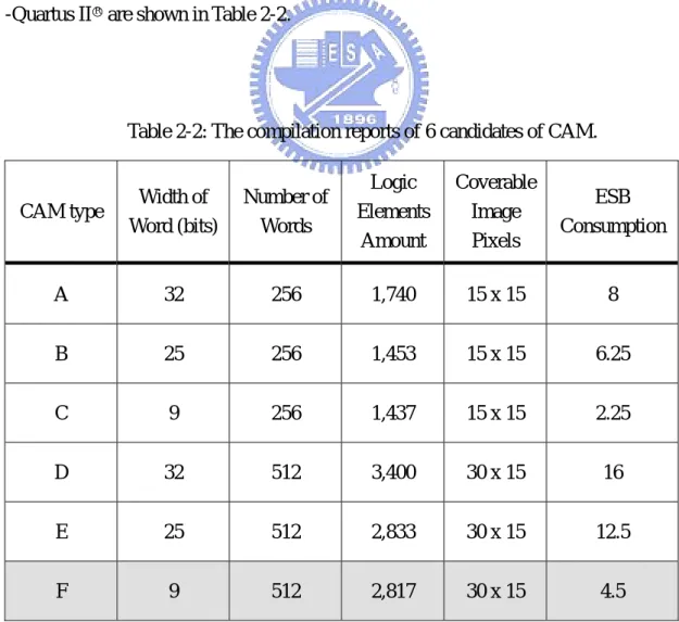
Table 2-2: The compilation reports of 6 candidates of CAM.
CAM type Width of Word (bits) Number of Words Logic Elements Amount Coverable Image Pixels ESB Consumption A 32 256 1,740 15 x 15 8 B 25 256 1,453 15 x 15 6.25 C 9 256 1,437 15 x 15 2.25 D 32 512 3,400 30 x 15 16 E 25 512 2,833 30 x 15 12.5 F 9 512 2,817 30 x 15 4.5
Table 2-2 indicates that each CAM has its largest storage as the number of words, and each word in the CAM is fixed in width. The logic elements amount shows the estimation of the basic logic gates usage of each CAM, and it could be the reference for the gate counts optimization in the future synthesis. The coverable image pixels are estimated by the number of words according to the adopted input image pixels, 30×15, and therefore only type D to type F could cover the whole input image. The final and the most important information in Table 2-2 is the ESB consumption, and it shows that only type F could reach the optimal condition. Hence, type F, the 9-bits 512-words CAM, is the chosen type of CAM in the proposed LPR system.
2.4.2 Pin Assignment and Function Test
The details of the pin assignment of the 9-bits 512-words CAM is shown in Figure 2-4. The pins wren and wraddress denote “Write Enable” and “Write Address” respectively, and they could allow the system input data in any appointed addresses in the CAM. The pin mstart indicates that a search operation is begun and forces the signal maddress to the first matched location. Then, maddress is moved to the next address by setting the input signal mnext high. The output signal mfound will stay high during the sequential transmission of maddress signals, and it will be reset to low once the transmission is over. The other pins, inclock, inclocken, and inaclr, are the
communication ports to the DSP control unit of the LPR system, and they enable the CAM to receive the clock signal and the signal from the DSP. Because the asynchronous clear operation is no need in the system now, the signal inaclr is reset to low as default. After the 9-bits 512-words CAM is constructed, it is necessary to check whether the searching function works well or not.
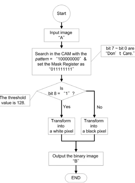
It is assumed that a 24bits, grey-level, and 30×15 pixels image “A” is needed to be transformed into a new binary image “B.” The presentation of the example is shown in Figure 2-5, and the flow chart of the test is shown in Figure 2-6. First, the image “A” is stored in the 9-bits 512-words CAM as shown in Figure 2-7. In fact, since “A” is a grey-level image, whose R value is equal to the G and B values, it is the 8 bits R value (bit 8 ~ bit 1) with an additional dummy bit “0” (bit 0) that stores in the CAM. From Figure 2-7 it is obvious to see the patterns are “C00” and “780” in the hexadecimal form at corresponding locations, the wraddress, of the CAM.
Figure 2-5: The function test of the proposed CAM.
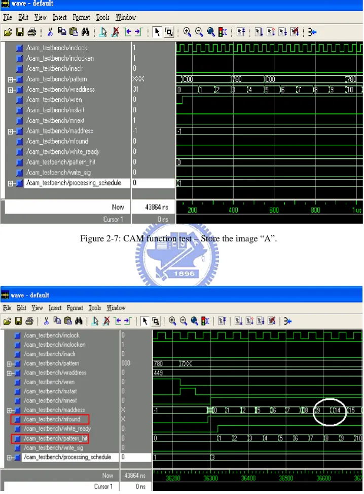
After “A” is stored, the search operation then starts. The CAM runs the multiple-matched mode by setting the mstart signal to high and searches the pixels with the grey-level value bigger than 128 as shown in Figure 2-8. Since the threshold 128 for the binarization means that the top bit of the pattern is “1,” other bits will be set “Don’t Care” in the operation, i.e., pattern = “100000000” and the Mask Register is enabled as “011111111.” As a result, the pin pattern shows a hex value “XXX,” i.e., the binary value “1XXXXXXXX” in the figure.
A great performance in search efficiency of CAM is shown in Figure 2-8. The highlighted signals mfound shows that after one clock of the multiple-matched start mstart, the matched data addresses maddress output in serial with a high mfound signal. The indices of the matched data are obtained just after one clock of mfound, so the number of matched data, the pattern_hit signal, could be counted right now. Therefore, the CAM saves much time in the data search procedure. Note that the addresses in the white circle area are “9” and “14” which show that the parallel search has done and the CAM would waste no more clocks to output the fitful indices.
The end of the multiple-matched addresses output sequence is shown in Figure 2-9. It clearly indicates that the final matched locations are the 447th to 449th pixels in the image “A.” Finally, the binary image “B” is created since the write_sig signal goes high, as shown in Figure 2-10. This function test is accomplished within 44μs.
Figure 2-9: CAM function test – End of multiple-matched addresses sequence.
This chapter has introduced the principle and the architecture of the Content Addressable Memory. A 9-bits 512-words CAM has been created for the storage of the LPR system. Since the CAM saves the processing time consumption of the proposed system, such performance will improve the Pattern Accumulated Vector method, which will be introduced in next chapter.
Chapter 3
The PAV Method for Character Recognition
In this chapter, the structure of CAM based on Pattern Accumulated Vector technique will be applied to the character recognition of a license plate. In general, there are three fundamental steps to fulfill an LPR system, including the license plate extraction, the character segmentation, and the character recognition. Since the structure of CAM is suitable for recognition problem [7], this chapter will focus on the character recognition in the LPR system. As for the license plate extraction and character segmentation, both are assumed well processed before the character recognition discussed in this chapter.
The license plate extraction and the character segmentation have been developed in the decades [1][4]. In Addition, the character recognition followed by the license plate extraction and the character segmentation also plays an important role in the LPR system. Pattern Accumulated Vector method, or PAV method for short, adopted for the robust character recognition will be introduced in this chapter.
3.1 Motivation
A basic and simple recognition method for the license plate characters recognition could reach the recognition rate of 80% per character. For example, a rate about 85% per character is typical for the template matching algorithm [24]. However, such a recognition rate is only for well-extracted characters. In practice, it is frequently hard to extract the license plate characters perfectly in outdoor environments, especially on roadways or highways. Although several methods have been proposed and obtained better results in character extraction, the extracted license plate characters couldn’t be always perfect [10][24]. That means some characters would be under-segmented or over-segmented under certain conditions, especially for the soiled characters, the dirty license plates, the blurred or over exposed license plate images. The characters in such kinds of environments usually have fragmented strokes, undesired shifted image, pared character images, or unwell-normalized images, and so on. Due to these uncertainties, if a basic recognition method is used, the recognition rate of these extracted characters may be reduced to less than 70% per character.
As a consequence, to establish robust character recognition algorithm is the most important part for the LPR system. This thesis presents a new type of feature vector called Pattern Accumulated Vector, or PAV for short, to represent each template. The PAV method adopts several suitable pattern blocks to accumulate the matched amount respectively in an image, and then reforms them into a feature vector type.
The pattern blocks have been widely utilized in the image compression [23] and video coding techniques [27]. In the image compression, the pattern blocks transforms 2-D local area color information into 1-D vectors for the similarity identification [3][22]. In the video coding field, the pattern blocks are adopted to check the moving and the still region in a series of frame images [25].
This chapter will show that the pattern blocks are also reliable for our LPR system since the pattern blocks haven’t been adopted in the character image recognition. This thesis utilizes the pattern blocks to develop the PAV method, and then uses the proposed method to recognize license plate characters. The fundamental of the pattern blocks and the principle of the PAV method will be introduced in the following.
3.2 Pattern Block
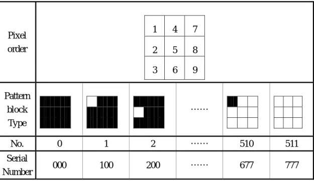
A pattern block is given as an l-by-l square binary image and then there are 2l types of pattern blocks. In this thesis, the size of a pattern block is chosen to be 3-by-3, which results in 29 = 512 types of pattern blocks as shown in Table 3-1. Each pattern block is denoted by a serial number (a1a2a3) where ai = 0, 1, 2, …, 7, for i = 1, 2, 3,
and is determined from the order of the pixels in the i-th column. For example, a serial number (206) represents a pattern block with pixels in the 1st column being 0, 1, 0 downwards, pixels in the 2nd column being 0, 0, 0 downwards, and pixels in the 3rd column being 0, 1, 1 downwards. Note that any sub-block of size 3-by-3 in a binary character image can be mapped to one of the 29 pattern blocks. Therefore, with these 29 pattern blocks, the character recognition based on binary image can be fulfilled.
Table 3-1: Different types of pattern block.
Pixel order 1 4 7 2 5 8 3 6 9 Pattern block Type …… No. 0 1 2 …… 510 511 Serial Number 000 100 200 …… 677 777
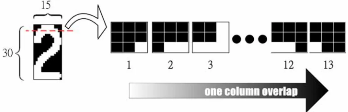
In the proposed LPR system, each pattern is yielded by a 3-by-3 overlap moving block. Let B be the binary input image with dimension h×w. This thesis adopts the binary image with dimension 30×15, i.e., h=30 and w=15. An example of the pattern obtainment process is shown in Figure 3-1. In the top three rows of the template “2,” we can divide the sub image into thirteen 3-by-3 pattern blocks by overlap one column in each move. After completing the procedure by overlapping one row or one column in each move, a 30×15 image will be separate into (30-2) × (15-2) = 364 pattern blocks since the 3-by-3 window cannot move over the image.
The result of the example is shown in Figure 3-2. It means that the template “2” could be extracted into all 512 types of pattern blocks. Furthermore, the amount of each type implies the importance of such pattern block corresponding to the template. As a consequence, this thesis uses the amount of the pattern block to develop the PAV method, which will be introduced in next section.
Figure 3-1: The pattern blocks in the top three rows of the template “2.”
3.3 Fundamentals of the PAV Method
The PAV method is based on a specific feature vector of an image called Pattern Accumulated Vector (PAV), whose entries are the accumulated amount of certain pattern blocks matching to the input image. The PAV method is used to identify the character of a test image. First, determine the distances between the PAV of the test image and the PAVs of all the template images in multiple dimension feature space. Since the distance is treated as a similarity index, the smaller the better, the character of the test image will be identified as the character of the template image with minimum distance. Once the minimum distance is obtained, the character recognition of the test image is completed.
The basic concepts about the proposed method are described as follows. There are 36 binary templates for the license plate characters, “0” to “9” and “A” to “Z,” denoted as B1 to B36 in order. These binary standard templates are shown in
Figure 3-3. Each 3-by-3 pattern block, given as (a1a2a3), would match all the binary
templates in an overlap way. The amount of 3-by-3 sub blocks in a binary template matched to the pattern block (a
n
B 1a2a3) is accumulated, and finally the matching
results of 512 patterns with 36 templates are shown in Table 3-2. Then, let (aaa),n
3 2 1
λ
be the matched amount of the pattern block (a1a2a3) to the binary template Bn in
Table 3-2. Once all the (aaa),n
3 2 1
vector
u
n of the template Bn is defined to have 512 components and eachcomponent is given as
( )
i
=
( 1 2 3),,
0
≤
i
≤
511
u
nλ
aa a n (3.1)where (a1a2a3)=(000) for i=0, (a1a2a3)=(100) for i=1, (a1a2a3)=(200) for i=2, and so
on. Define as the feature vector of the test input binary image, and its distance to is computed as t
u
nu
(
) (
)
[
]
, 1 36 dt,n = ut −un 2 = ut −un T ut −un ≤n≤ (3.2) which is the Euclidian distance. Finally, the character of the test binary image will berecognized as the character of whose distance is minimal. This accomplishes the character recognition, and is the fundamentals of the PAV method.
k
B dt ,k
However, if the entire 512 pattern blocks are adopted in the above procedure, i.e., is in a 512-dimensional vector space, the time consumption will increase tremendously and slow down the recognition process. Fortunately, Table 3-2 shows that most of the pattern blocks have nothing to do with the features of all the templates, such as the pattern block (200), and thus these kinds of pattern blocks can be deleted to improve the computation.
n
u
After the deletion of some useless pattern blocks, the improved computation is the so-called PAV method. In other words, the PAV method first chooses the most useful pattern blocks and then forms the pattern accumulated vectors for the further
character recognition. Without the pattern blocks choosing procedure, the method will become time consuming extremely. Such procedure is called the recursive selection of the principal pattern blocks, which will be developed in next section.
Figure 3-3: The binary standard templates.
Table 3-2: The matching results of 512 patterns with 36 templates. Templates Pattern SN 0 1
B
1 2B
2 3B
… 9 10B
A 11B
B 12B
… Y 35B
Z 36B
(000) 73 85 91 … 76 50 73 … 132 107 (100) 1 0 11 … 1 2 2 … 2 7 (200) 0 0 0 … 0 0 0 … 0 0 . . . . . . . . . . . . . . . . . . . . . . . . . . . (773) 5 0 14 … 5 5 6 … 4 9 . . . . . . . . . . . . . . . . . . . . . . . . . . . (677) 7 2 13 … 8 5 7 … 2 9 (777) 126 211 94 … 98 125 135 … 78 112 total 364 364 364 … 364 364 364 … 364 3643.4 Recursive Selection of the Principal Pattern Blocks
The selection of the principal pattern blocks consists of two major steps. Step one is to delete the useless pattern blocks and then form a set of pattern candidates. In Step two, further choose the principal pattern blocks from the set of pattern candidates. The selection of the pattern candidates is based on several criteria to make the recursive procedure more efficient in computation. The selected principal pattern blocks will make the PAV method reliable in the character recognition.
Since a 3-by-3 pattern blocks includes totally 512 types and some types such as pattern block (200) would never match any one of the templates, it is needed to reduce the usage of pattern blocks. Besides, there must be several principal pattern blocks among 512 types to distinguish the entire 36 license plate characters. To achieve the goal, the criteria for the pattern candidates selection in Step one have been developed. The criteria are presented as below:
1. At least one (aaa),n
3 2 1
λ in the same pattern block (a1a2a3) is non-zero.
2. In the same pattern block (a1a2a3), the largest difference between any two
(a1a2a3),n
λ is 5 or over.
3. The pattern block (a1a2a3) matches only 1 or 2 templates.
where the 1st and 2nd criteria are the necessary conditions, except for the particular condition of the 3rd criterion. Before the details of the criteria, some parameters must
be introduced.
According to the (aaa ),n
3 2 1
λ shown in Table 3-2, an important information of the pattern block (a1a2a3) related to all the templates Bn is assigned by the number defined
below ( )
∑
(
( ))
= = 36 1 3 2 1 3 2 1 i ,i a a a a a a signλ N (3.3) where(
( ))
1 3 2 1aa i = a , signλ for ( ) 0 3 2 1aa i> a , λ and(
( ))
0 3 2 1aa i = a , signλ for ( ) 0 3 2 1aa i= a , λ . is limited to 1 or 2 for the 3(a1a2a3 N ) 3 2 1 rd
criterion. Moreover, the matched numbers corresponding to different templates by a certain pattern block are usually distinct, and the feature would improve the recognition result. Therefore, we define the maximum difference between any two λ(aaa ),n in the same pattern block (a1a2a3) as
(a1a2a3)
=
max
{
λ
(a1a2a3),n1−
λ
(a1a2a3),n2}
,
1
≤
n
1≠
n
2≤
36
λ
(3.4) where (aaa ),n 1 3 2 1 λ and (aaa ),n 2 3 2 1 λ are two (aaa),n 3 2 1 λ corresponding to different Bn inthe same pattern block (a1a2a3). After Step one the candidate will increase, so we
define the i-th principal pattern block candidate as
(
a1a2a3Pi=
)
(3.5)which is each component of the candidate set P. After P is formed, pick off each one in order at a time and re-check the recognition rate. The candidate is kept in P if the recognition rate decreases. After Step two, all candidates in P are checked and all pattern blocks (a1a2a3) are tested, and then the recursive selection is completed and
the final pattern blocks candidates are yielded. Therefore, the set P would be the set of the principal pattern blocks as
{ }
, 0≤ ≤ −1 = P i mP i (3.6)
where m is the total number of the principal pattern blocks in P. The number and the type of the principal pattern blocks would change due to different templates.
The flow chart of the recursive principal pattern block selection criteria is shown in Figure 3-4. It indicates that there are two sub-loops in a single procedure, which are Step one and Step two. The first sub-loop could be viewed as the selection of a single pattern block (a1a2a3), while the second one is the final adjustment of P to decide the
m principal pattern blocks. After the accomplishment of the selection, the principal pattern blocks will be chosen. The fixed thresholds in each criterion are made by some analyses, which will be introduced in next section.
3.4.1 Threshold Decision of the Criteria
There are three threshold values adopted in the recursive selection procedure, the lower bound of the amount of non-zero (aaa),n
3 2 1
λ in the same pattern block (a1a2a3),
the value ( ) 5
3 2 1aa =
a
λ , and the summation ( )
{ }
1,23 2 1aa =
a
N . Before setting them, a statistics about the distribution of the amount of successful recognition cases has been established in Table 3-3, and the recognition is tested with 36 license plate template characters. The table obviously indicates that there are 416 types of pattern blocks useless for the character recognition, so only 96 types of the pattern blocks are available. As a result, the first step is to delete the pattern blocks that match none of the templates by setting the lower bound ( ) 1
3 2 1aa n=
a ,
λ . The second threshold is the lower bound of (
3 2 1aa
a
λ ). A general way of recognizing more objects in certain dimension is to make the minimum distance between them be larger and larger. Since each (aaa),n
3 2 1
λ in the same pattern block (a1a2a3) is fixed, it is needed to find a suitable pattern block (a1a2a3) with the λ(a1a2a3)
big enough. In addition, different Bn usually brings different λ(a1a2a3),n in the same
pattern block (a1a2a3), and Table 3-2 shows that a small change of the number of
(a1a2a3),n
λ usually yields the construct of other Bn . Therefore, the threshold of λ(a1a2a3)
The final threshold is the limitation of . From Table 3-3 it shows that there are 11 and 31 types of pattern blocks which could recognize only 1 and 2 characters, respectively. Although their recognition rates are very low, they could be viewed as the particular patterns corresponding to the recognized characters. In other words, the 3 (a1a2a3 N ) ) 3 2 1 rd
criterion is the particular condition, which is contrary to the 2nd one as the general condition. To spotlight the uniqueness of such pattern block, the value of
is limited to the amount of 1 or 2 after the judgment of the 2
(aaa
N nd criterion.
After the decision of the criteria, the recursive selection of the principal pattern blocks starts. The candidate pattern blocks are chosen during the flow chart displayed in Figure 3-4. Finally, the m principal pattern blocks are obtained, which will be shown in next sections.
Table 3-3: The distribution of the amount of successful recognition cases. Total character recognition amount
(Total:36)
Number of capable pattern blocks 0 416 1 11 2 31 3 26 4 7 5 7 6 2 7 3 9 3 11 1 12 1 14 2 15 1 16 1 Sum : 512
3.5 The Basic PAV Method
To get the principal patterns through the recursive pattern selection procedure, the 36 templates from “0” to “9” and “A” to “Z” are input as the references. Furthermore, the input templates shown in Figure 3-3 are standard without any inclined, fragmented, and shift conditions, etc. Thus, the principal pattern blocks for the standard templates will be obtained, and the method with these standard templates is called the basic PAV method.
A traditional method, which tests the entire possible pattern sets in 512 pattern blocks, can finally get the principal pattern blocks, too. But, the largest disadvantage of such method is that it is tremendously time consuming. In the standard templates case, all the possible combination of pattern blocks among totally 512 pattern blocks are tested and their recognition rates are recorded. Let x be the number of selected pattern blocks, and there will be possible sets in the x-th stage combination. Then, the max recognition rate and the corresponding combinations of each stage are picked up, and the max recognition rate distribution of x selected pattern blocks is shown in Figure 3-5. It implies that the recognition rate could reach 100% even when x<50. The x-axis is then zoomed in as shown in Figure 3-6, and it clearly indicates that the recognition rate reaches 100% at x=12. As a result, the basic principal pattern blocks are finally decided, although there are more than one decided sets. However,
512
this traditional way costs too much time, almost 24 hours, to complete. In other words, it is not an efficient way to get the basic principal pattern blocks.
Figure 3-5: The max recognition rate distribution of x selected pattern blocks.
The recursive selection of the principal pattern blocks in section 3.4 is an efficient method to obtain the needed principal pattern blocks. It deletes the useless pattern blocks at first, and then chooses the principal pattern blocks from the set of pattern candidates. After the recursive procedure, the basic principal pattern blocks for the standard 36 templates are yielded and listed in Table 3-4. Obviously, the total number of the principal pattern blocks by the recursive procedure is the same as the number by the traditional way, i.e., m=x=12. In addition, the proposed selection costs less than 3 hours to accomplish. That is, the recursive selection in Figure 3-4 is a systematic and efficient method to decide the m principal pattern blocks.
The 12 principal pattern blocks in Table 3-4 could be clustered as three categories due to their black and white region relations. These categories are bar, special, and triangle forms; each of them contains four pattern blocks. The recognition capability of each single pattern is also listed in the table, and then all principal pattern blocks are sorted in descending order by the amount of recognized characters.
Table 3-4: 12 principal pattern blocks for 36 standard templates.
Category Pattern SN.
Amount of recognized characters
Data of recognized characters
bar 077 16 1, 3, 7, A, C, D, E, H, J, M, N, R, V, W, Y, Z bar 770 15 0, 1, 4, 7, 9, B, D, H, J, K, L, Q, U, V, W special 773 14 0, 2, 4, 5, 6, 8, B, F, L, N, Q, W, X, Z special 677 14 0, 2, 4, 5, 8, 9, B, H, N, O, S, W, X, Z bar 333 12 5, 6, 7, 8, E, F, H, I, P, R, T, Z bar 666 11 2, 3, 5, 6, B, E, G, J, L, S, Z special 740 9 0, 3, 8, A, I, K, N, S, X triangle 731 7 2, 3, 6 , C, J, O, Q triangle 764 7 5, 9, G, L, P, S, Y triangle 467 7 0, 2, 8, 9, M, O, U triangle 137 6 0, 2, 6, B, O, S special 047 5 4, A, O, U, Z
The basic PAV method is stated as below. Since the 12 basic principal pattern blocks are chosen as Table 3-4, equation (3.5) would be updated to ,
,
( )
077 0= P( )
770 1= P P2=( )
773 , P3=( )
677 , P4=( )
333 , P5=( )
666 , , ,( )
740 6= P( )
731 7=P P8=
( )
764 , P9=( )
467 , P10=( )
137 , and P11=( )
047 . Hence, the vector given in equation (3.1) would be changed ton
u
( )
i
=
,,
0
≤
i
≤
11
v
nλ
in (3.7)where
v
n is the so-called pattern accumulated vector of the template Bn , and λi,nis the coefficient of Pi corresponding to Bn . Further Define as the pattern accumulated vector of the test binary image, and its distance to given in (3.2) is now updated as t
v
n t , d(
) (
)
[
]
, 1 36 dt,n = vt −vn 2 = vt −vn T vt −vn ≤n≤ (3.8) which is still the Euclidian distance. Finally, the character of the test binary image willbe recognized as the character of whose distance is minimal. That is, the pattern accumulated vectors of all 36 standard templates are obtained after equation (3.7) and shown in Figure 3-7 to Figure 3-15, and the basic PAV method is accomplished by equation (3.7) and (3.8).
k
Figure 3-7: The PAV of templates “0” to “3.”
Figure 3-9: The PAV of templates “8” to “B.”
Figure 3-11: The PAV of templates “G” to “J.”
Figure 3-13: The PAV of templates “O” to “R.”
Figure 3-15: The PAV of templates “W” to “Z.”
3.6 The Improved PAV Method
In the previous sections, the basic PAV method has been introduced. Additionally, the 12 principal pattern blocks for the standard templates have been developed. In this section, the improved principal patterns for the deformed templates will be discussed, and they will deal with the problems such as the inclined, noised, over-segmented, and under-segmented license plate characters. The method using the improved
The templates database in Figure 3-3 is now increased from the original 36 standard characters to the improved 108 character templates containing the rightward and leftward directions of 30 degrees inclined conditions. Hence, the raw data about the distribution of recognition amount is shown in Table 3-5. Although the total capable number of patterns is the same, the distribution has changed from the results of Table 3-3.
Table 3-5: The distribution of the amount of recognitions for improved database. Total character recognition amount
(Total:36) Number of capable pattern blocks
1 17 2 35 3 16 4 8 5 6 6 3 7 3 9 4 11 1 12 1 13 2 15 1 16 1 Sum : 96
The traditional way presented in the previous section could be applied here again, and then the max recognition rate distribution of x improved pattern blocks is shown in Figure 3-16, and the x-axis is further zoomed in as shown in Figure 3-17. The latter clearly indicates that the recognition rate reaches 100% at x=16. As a result, the improved principal pattern blocks are finally decided, and the amount of them is 16. Since the traditional way still costs too much time, the recursive selection of the principal pattern blocks is adopted to replace it.
Figure 3-17: The max recognition rate distribution in 20 improved pattern blocks.
After the recursive procedure, the improved principal pattern blocks for the deformed templates are obtained and shown in Table 3-6. They could be clustered as four categories: bar, special, triangle, and box forms; each of them contains four pattern blocks. Obviously, the total number of the principal pattern blocks by the recursive procedure is the same as the number by the traditional way, i.e., m=x=16. Moreover, the recursive selection still costs much less time than the traditional way. That is, the proposed recursive selection could find a suitable principal pattern blocks set for the templates in an efficient way.