T. S. Liu
J. Y. Lee
Department of Mechanical Engineering, National Ciiiao Tung University, Hsinctiu 30010, Taiwan
A Similarity IVIetliod for
Miniature IVIobile Robots
Taking advantage of a piezoelectric material to fabricate miniature mobile robots, this study presents a similarity method, fabrication process, and walking experiment method. A curved piezoelectric material is first analyzed for vibration behavior in order to provide a basis for deriving model laws. Since the behavior of miniature mobile robots is not amenable to modeling, the similarity method is carried out to obtain model laws. A prototype for the miniature robot is further scaled down in different geometric sizes to conduct walking experiments. Experimental results that are primarily concerned with walking speeds comparison among robots of different sizes serve to verify model laws.
1 Introduction
Applications of microelectromechanical systems (MEMS) are emerging in optics, medical, chemical and biological pro-cesses, measurement and instrumentation, and robotics. To real-ize MEMS in practice, not only microsensors but also micro or miniature actuators are demanded. Miniature mobile robots, if equipped with microsensors, are anticipated to undertake in-spection, maintenance, and diagnosis in such compact environ-ments as telecommunication tubes, power plants tubes, petro-leum tubes, turbojet engines, human organs, etc. To this end, it is desired to scale down or redesign mobile robots to accommo-date compact environments that have been intangible to humans. There have been papers on the design of and experiments with miniature robots (Aoshima et al., 1993; Okada and Sanemori, 1987). However, due to their unusual dimensions compared with conventional machines, theoretical analysis is difficult and remains scarce.
The current study aims to present similarity methods for min-iature mobile robots. Since minmin-iature robots in this paper are made of a piezoelectric material, their motion is caused by the converse piezoelectric effect and controlled by voltage. Owing to the friction force that acts between the miniature robot and contact surface, the miniature robot can walk on a surface. This study develops the similarity method to predict performance of miniature robots in different weights, sizes, and input voltages. Walking experiments that are primarily concerned with walking speeds are carried out to verify theoretical results.
The similarity method has been used for a variety of applica-tions such as physics (Mansour and Chigier, 1991), mechanical design (Schnittgar, 1988), vibration systems (Stachowiak and Brodzinski, 1985), and solid mechanics (Brodich, 1993; Alex-eyev et al., 1992) in addition to numerous works on thermal and fluid systems (e.g., Russell and Canfield, 1972; Shannon, 1973).
The similarity method provides the following advantages: 1. Whenever a machine is scaled or system modeling is not
easily established, the similarity method can lead to model laws such that physical performance can be pre-dicted.
2. If equations of motion are too complex to solve, it is feasible to obtain crucial information without solving equations.
The similarity method may become an important tool for the development and design of miniature robots and actuators (Pust,
Contributed by the Dynamic Systems and Control Division for publication in the JOURNAL OF DYNAMIC SYSTEMS, MEASUREMENT, AND CONTROL. Manuscript received by the DSCD July 12, 1995. Associate Technical Editor; T. Alberts.
1993). Playing the central role in the similarity method, model laws can be obtained by either introducing scale factors into differential equations or via the Pi theorem.
The remainder of this paper is organized as follows. Section 2 formulates vibration equations for piezoelectric material in order to characterize the miniature robot vibration. Section 3 describes the similarity method. Section 4 presents the fabrica-tion process of miniature robots. Experimental results for walk-ing speeds at various excitation frequencies and voltages are carried out. Experimental results serve to validate the similarity method. Section 5 concludes this study.
2 Vibration Equation
To carry out the similarity method, vibration equations are formulated first. Since the miniature robots fabricated in this study are in an archlike geometry, as shown in Fig. 1(a), they can be treated as curved beams. Considering an element of the piezoelectric film shown in Fig. \{b), with applied forces its equation of motion in the radial direction has the form
dS ,, , d'-u
ae dt"- (1)
where S denotes the shear force, N the normal force, 6 the curved angle, m' the mass per unit length, r the radius of the centroidal axis on film cross section, and u the inward radial deflection for the piezoelectric film. The equation of motion in the tangential direction is written as
ON „ , a v
(2)where w denotes the tangential deflection. The moment equation is written as
dM,
+ Sr = 0 (3)
where Mi, denotes bending moment and the rotary inertia is neglected.
The inextensionality condition along the centroidal axis re-quires that w and u be related by
dw
'89 (4)
Moreover, the bending moment Mj is related to the change in curvature by (Davis et al., 1972)
( a )
N + d N
Mb+dMfc \
o
( b )Fig. 1 Photo of the proposed miniature wallcing robot and definitions of deflection, force, and moment for an element of piezoelectric film
, , EI / d^u
(5)
where E and / denote Young's modulus and second moment of inertia for the film, respectively. As a result, Eqs. (1) - (5) lead to a sixth-order partial differential equation in terms of w, i.e..
EI
1-2 1
Q6 " a/)4 Qo2 dt^e'' (6) Assuming that both ends (^ = 0 and (f>) are free, boundary conditions based on shear forces, normal forces, and moments can be expressed by (Aoshima et al., 1993)
Shear force: S = -EI fd\v
89'*
de'
= 0at e = 0,<t> (7) XT , f ,, , d^w El/d'w d'w\ ^ Normal force: A^ = m r r -I—r — - H = 0
at e = 0,(1) (8) Moment: M = - \^— + ^ j = M,„ sin Qt
at e = Q,(p (9) where M„„ = (bhdjiEr^V,„)/EI represents the maximum of the bending moment M„ due to applied voltages. Note that d^i
de-notes a piezoelectric strain constant, b the width of the miniature robot, h its thickness, and Ki the amplitude of input sinusoidal voltages.
Assume the solution of Eq. (6) is of the form
w(9,t) = H{e)-T(t) (10)
Substituting Eq. (10) into Eq. (6) gives, with fi being the resonant frequency. ffW ^ 2//(*) + 1 where
— uAH" + — n'H=0 (11)
EI I EI
T + n^T
( ) ' = — ( ) and (•) = - ( ) do dt (12)From Eq. (11) one can define
EI
n'
(13)where 6^ is a positive constant. Following the similarity method (Sedov, 1993), Eq. (13) will be used to formulate a model law.
3 Similarity Method
In setting up experiments, the concept of similarity can be used to scale up or down for a prototype. The similarity method that is based on the dimensional analysis has become an im-portant mathematical technique. The dimensional analysis not only can reduce the number of experimental variables and hence save time in experimental procedures, but can also help us ascertain mutual relationships among physical parameters.
Among several systems of fundamental dimensions, two main systems are the MLT system (in terms of mass, length, and time) and the FLT system (in terms of force, length, and time). Depending on the ease of computing dimensional matri-ces, either the MLT or FLT system is employed. If the system dealt with is not only related to mechanical fields, but also involves electrical effects, an additional fundamental quantity should be incorporated. Therefore, a new dimensional symbol Q is employed in this study to represent electric charge and the standard unit of electric charge is Coulomb.
Similarity is defined as follows (Bridgman, 1931): a function / ' is similar to a function/, provided the ratio/ 7 / is a constant, when the functions are evaluated for homologous times. The constant K„ = n'/n is called the scale factor for the function/. Using the similarity method (Murphy, 1950; Baker, Westine, and Dodge, 1973; Sedov, 1993) important information can be uncovered based on the formulation for dynamic equations but without solving them. This method not only characterizes scale factors, including the mass, length, time, and electric charge, but also preserves the original form for equations of motion.
The Pi theorem (Buckingham, 1914) forms the basis for investigating physical relationships within the framework of similarity. According to Bridgman (1931) for the Pi theorem, if (l)(a, p, y, — ) = 0 is a complete equation, the solution has the form F(IIi, II2, II3, — ) = 0 where the Pi terms IPs are the n-rank independent products of the arguments a, P, 7,
etc., which are dimensionless in fundamental units. The Pi theorem demands that every physical relationship be-tween n physical quantities be reduced to a relationship bebe-tween k = n-rank mutually independent dimensionless groups, where rank represents the rank of the dimensional matrix, made up of physical quantities of interest and generally equal to the number of basic quantities contained in them. In order to determine the
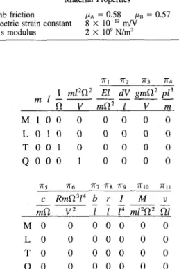
Table 1 Parameters for miniature mobile robots
Parameter Symbol Unit Fundamental Dimension Category
Young's modulus Piezo strain constant Mass
Density
Damping coefficient Piezo stress constant Resistivity
Width Length Radius
Second moment of inertia Curved angle Coefficient of friction Voltage Angular frequency Moment Walking speed E d m P c g R b I r I
e
A* Vn
M V N W mA' kg kg/m' N-S/m V-m/N Ohm/m' m m m m^ 1 1 V 1/s N - M m/s M'L-'T-^Q" -] M-'L-'T^Q' ^iLO-pOgO M ' L - ' T V M'L°T-'Q'' M V T O Q - ' M'L^T-'Q-^ J M^L'TV -M^L'T-'Q" M^L'T^Q" M V T V— J
•— _ M'L^T-^Q-' MVT-'Q" J M'L^T-^Q" M'-L'T-'Q" J Material Properties Geometric Shapes Environment factors Input Responserank of a dimensional matrix, one can use linear algebra. The rank can be prescribed as follows (Pust, 1993):
1. rank = 2 corresponds to kinematic and static problems; 2. rank = 3 corresponds to dynamic problems;
3. rank = 4 corresponds to mechatronic problems.
The majority of physical quantities can be divided into five categories: 1. geometric parameters 2. material parameters 3. environment factors 4. input parameters 5. response parameters
In this study, the pertinent physical parameters are expressed by
(/)(£, d, g, m, p, c, R, I, b, r, I, 9, fi, V, ft, M, v) = 0 (14) where d denotes the piezoelectric strain constant, g stress con-stant, p density, c damping coefficient, R resistivity, / robot length, V input voltage, M bending moment, and v robot walking speed. These seventeen parameters needed to define the system are summarized in Table 1, where their fundamental dimensions include mass M, length L, time T, and charge Q. Since the miniature robot belongs to an electromechanical system, the rank of the dimensional matrix is four. It follows from k = n-rank that due to this group of seventeenth parameters, thirteen Pi terms can be created. This list of parameters can be reduced from seventeenth to thirteen by calculation. It is found in Eq. (14) that two Pi terms, namely, curved angle 6 and friction coefficient jx have already been nondimensional and thus can be ignored. The remaining fifteen quantities with their fundamental dimensions M,L, T, and Q are arranged in matrix form:
Piezoeleotrio B i m o r p h
C y l i n d e r
«! a^ a-i 04 Us Uf, 07 ag Qg aio an a\i ai3 AH «I5
E d g m p c R l b r l Q . V M v
M l - 1 0 1 1 1 1 0 0 0 0 0 1 1 0 L - 1 - 1 2 0 - 3 0 0 1 1 1 4 0 2 2 1 T - 2 2 0 0 0 - 1 - 1 0 0 0 0 - 1 - 2 - 2 - 1 Q O 1 - 1 0 0 0 - 2 0 0 0 0 0 - 1 0 0 To deal with this matrix, interchange the fifteen columns, so that 04, flg. «i2. and a^ are moved to the first four columns for ease of subsequent manipulation; i.e.,
at, at ai2 a^ Oi 02 a, a^ a^ a^ ag a^ an au a,,
m I U V E d g p c R b r I M V M l O O 1 1 - 1 0 1 1 1 0 0 0 1 0
L O l O 2 - 1 - 1 2 - 3 0 O i l 4 2 1 T 0 0 - 1 - 2 - 2 2 0 0 - 1 - 1 0 0 0 - 2 - 1 Q O O O - I O 1 - 1 0 0 - 2 0 0 0 0 0 First develop an identity submatrix by devising appropriate products of the parameters, m,l,Q,, and V. The resulting identity submatrix is contained in the following matrix:
, 1 m I — MlOO L 0 1 0 T 0 0 1 e 0 0 0 V 0 0 0 1 E d g 1 - 1 0 - 1 - 1 2 - 2 2 0 0 1 - 1 P 1 - 3 0 0 c 1 0 - 1 0 R b r I 1 0 0 0 0 1 1 4 - 1 0 0 0 - 2 0 0 0 M 1 2 - 2 0 V 0 1 - 1 0 To obtain Pi terms, the last eleven columns are combined with the first four columns by conducting divisions and multipli-cations to make the resulting product nondimensional. The di-mensional matrix that contains eleven Pi terms can thus be expressed as
Electrical Adhesive Tape
S c o t c h Adhesive Tape
Fig. 2 Piezoelectric bimorph on a piece of Scotch adhesive tape around
Table 2 Geometric and material properties for miniature mobile robots
Miniature mobile robot Length Width Thickness Coulomb friction Geometry A 3.3 cm 2 cm 80 ^m Material Properties Piezoelectric strain constant
Young's modulus //A = 0.58 2.5 1.5 80 MB = 8 X 10~'^ m/V 2 X 10' N/m^ B cm cm fj,m 0.57 C 1.65 cm 1 cm 80 /^m Mc = 0.61 7^2 TTa TTA m I M 1 0 L 0 1 T O O Q 0 0 •n-s c mO M 0 L 0 T 0 Q 0 1 0 0 0 1 0
mPn
V 0 0 0 1 TTaRmnY
V
0 0 0 0 ' El TTv b I 0 0 0 0 0 0 0 0 TTg r I 0 0 0 0 dV gmQ.^ I V 0 0 0 0 •Kg I I' 0 0 0 0 0 0 0 0 TTlo Mml'n^
0 0 0 0 pi' m 0 0 0 0 7I"ll V Q.I 0 0 0 0T h e remaining eleven columns represent exponents associated with each of the eleven Pi terms. It is observed that the parame-ter E associated with ai appears only in the numerator to the first power. This parameter will appear in none of the other Pi terms. T h e same observation can be made for the other parame-ters. From the formulated Pi terms in the above dimensional matrix, dimensional analysis for Eq. ( 1 4 ) yields
/ El dV
gmO."-\mQ,^ ' I ' V
M
mi^n^' ni
0 (15)Voltage (V)
Fig. 5 Measured walking speed variation with frequency and voltage for miniature mobile robot B
N e w Pi terms concerning response parameters may be ob-tained by combining Pi terms anew. Hence,
7ri2 TTB - TTiTT^TTn TTzTTsTTio vEKr
v
MRmdn^ EVLet TTii be replaced by TTU and TTIO by TT^, Eq. ( 1 5 ) hence yields
j,( El dV gmQ^ pl^ _c_ RmVlY \mVl^' I ' V ' m ' mft' V^ '
b r I MRmdfl^ vERl^
I' I' I'' EV = 0 (16)
In order that the unknown function f i has the same value for the model as that for the prototype, the corresponding Pi terms of both systems must be equal; i.e..
El ^ E'l' dV^d^ gmn^ ^ g'm'Q^
mfi^ m ' Q ' 2 ' / " / ' ' V ~ V ' " " ®"^' In terms of scale factors K„ = n'/n with n = E, d, g,m, p, c,
500 1000 Frequency (Hz)
500 1000 Frequency (Hz)
Fig. 4 Measured walking speed variation with frequency and voltage Fig. 6 Measured walking speed variation with frequency and voltage for miniature mobile robot A for miniature mobile robot C
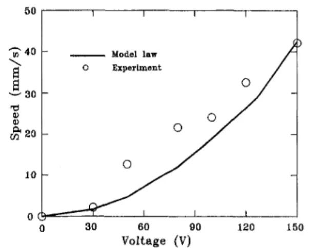
50 130 T3 10 -1 D 1 - Model law Experiment 1 1 1
/u
1 1 -30 60 90 Voltage (V) 120 150Fig. 7 Walking speeds under different voltages for miniature mobile robot A 50 •40 30 20 10 ^(^ Model law Experiment o o o o 60 90 Voltage (V) 120 150 Fig. 9 Walking speeds under different voltages for miniature mobile robot C
/?, /, fo, r, 1, Q,, V, M, and v, the mutual relationships of scale factors are written as
KEKI = K,„Kn', KgK,„Kii = Kv; Kc = K^KQ, Kb = Kr = Ki; KMKRK,„K^KQ = KEKV , KgKgK^Ki = Kv KdKv = Ki KpKi ~ K,„ KRKIIIKQKI = Kv K, = K1 (17)
Consequently, Eq. (17) constitutes model laws used to predict dynamic behavior for miniature robots. In a similar manner, Eq. (13) leads to a model law expressed by
K'„K,Kn — KgKi (18)
4 Walking Experiments
The miniature mobile robots fabricated in this study are made of polyvinylidene fluoride (abbreviated as PVDF or PVF2) that is a semicrystalline piezoelectric polymer (Broadhurst, 1980). PVDF is characterized by such properties as flexibility, softness, having low mass, and relatively low acoustic impedance. When PVDF films are injected with a controlled voltage, several types of deformation will appear such that the films may uniaxially
or biaxially stretch or shrink, transverse expansion, bend, and twist.
The exploration of PVDF applications based on the electro-mechanical energy-conversion principle has increased rapidly. PVDF films are used in various fields such as microactuators (Wang et al., 1989; Brei and Blechschmidt, 1992), intelligent actuators (Crawley and Luis, 1987), micromanipulators (Ume-tani, 1978), active vibration control (Baily and Hubbard, 1985; Tzou and Gadre, 1988), and scanning sonars (Gallantree,
1983).
4.1 Experimental Setup and Fabrication. In the setup of walking experiments, a function generator is connected to a power supply and the output AC voltage of the power supply is applied to a miniature mobile robot that is placed on a hori-zontal table. Five major steps are undertaken in fabricating each miniature robot:
1. Measurement of the Maximum Strain Direction. The maximum bending direction, which is perpendicular to the max-imum strain direction, is identified to facilitate walking.
2. Film Cutting. The piezoelectric material PVDF is in the presence of electrode layers on both surfaces. When cutting out the PVDF film, there is a risk of a permanent short circuit since the edge of the PVDF electrode layers may be damaged during cutting.
3. Determination of Film Polarity. To bond together two PVDF films, the polarity of each film has to be determined first.
50 40 10
s
^ 3 0 T3 10 -1 A . Model law Experiment 1 A y A y 1 A / 1 ' -— 30 60 90 120 150 Voltage (V) Fig. 8 Walking robot Bspeeds under different voltages for miniature mobile
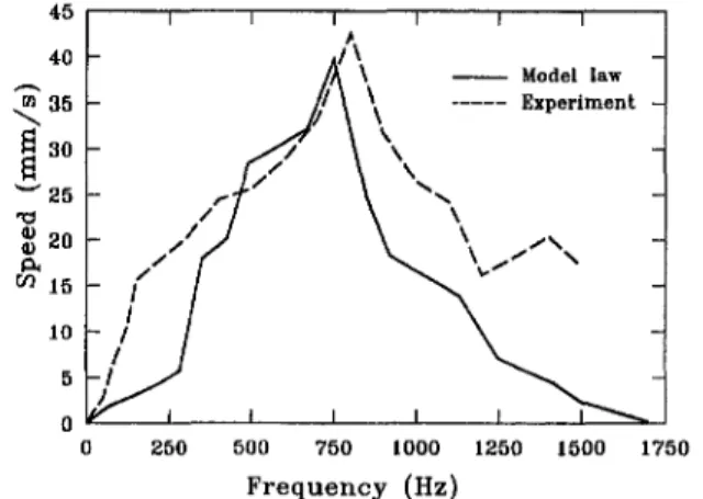
Model law Experiment
Frequency (Hz)
Fig. 10 Comparison of theoretical and experimental results under 150 V for miniature mobile robot B
30
2000
Frequency (Hz)
Fig. 11 Comparison of theoretical and experimental results under 100 V for miniature mobile robot B
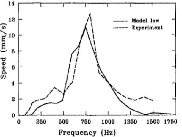
0 250 500 750 1000 1250 1500 1750
Frequency (Hz)
Fig. 13 Comparison of theoretical and experimental results under 150 V for miniature mobile robot C
4. Bonding of Films. It is important to ensure that the bonding layer be as soft as possible to avoid allowing the bond-ing layer stiffness to influence bendbond-ing deflection.
5. Curved Forming. The piezoelectric bimorph is wrap-ped tightly around a cylinder, for instance, a pencil, and secured with a Scotch tape as shown in Fig. 2.
4.2 Experimental Results. The electrical adhesive tape in the bonding layer is pasted off the center of gravity of the piezoelectric film, as depicted in Fig. 3, such that the center of gravity of the entire robot is located at the rear. This makes kinetic friction, between the table and film, at the rear larger than that at the front. Accordingly, the miniature mobile robot can walk forward. Moreover, three miniature mobile robots namely A, B, and C having different geometric sizes are fabri-cated. Their geometric sizes are specified in Table 2, Walking performance is examined in two aspects; namely speed versus frequency and speed versus voltage.
Whenever a robot is excited at its resonant frequencies, its walking speed may reach a maximum value. The maximum speed is almost the same as shown in Figs. 4, 5, and 6 for robots A, B, and C, respectively. Concerning the average speed, robot C is the fastest, since its weight is the lightest and hence its friction force is the smallest. Comparing Figs. 4, 5, and 6, the frequency values are C > B > A at respective maximum speeds. According to Eq. (13), this result is reasonable in view of the fact that robot C is the lightest while A the heaviest. In addition, when the output frequency of the function generator remains constant, the larger the AC voltage is, the faster the robot can walk. The speed versus voltage relationships, as shown in Figs. 4, 5, and 6, are almost linear.
Experimental results serve to verify model laws. Treating robot A as a prototype, scale factors of B and C in terms of both length and width are 0.75 and 0.5, respectively. In Table 2 that accounts for robot dimensions in experiments, the thick-nesses are not scaled in the same way as their lengths and widths, since we met difficulty in obtaining 60 and 40 lira thick PVDF sheets for fabricating robots B and C, respectively. Even if so, the consistency between the experimental and model law results will show that the thickness is not actually an important factor in the dynamic response of the robots. Two kinds of experimental results will be predicted by model laws. When geometric sizes remain the same whereas applied voltages are varied (i.e., for a given robot), the model law KEKRK^KI = K\ in Eq. (17) is employed and reduced to
K„ — Ky (19)
since KE = KR = Ki = 1 under the specified condition. Equation (19) can be stated as u' = {vlV^)iV'^). At each robot's reso-nant frequency, D and V represent the maximum experimental voltage and corresponding velocity, respectively. Accordingly, Figs. 7 to 9 compare results between model law Eq. (19) and experiments. The error for robot C appears to be the largest since it is the Ughtest. It requires the smallest driving force and, at input voltages lower than 100 V, can walk faster than the other two. Secondly, to deal with various geometric sizes at a constant voltage, substituting model laws K^ = KpK], K^ = Ki, and K, = Kj in Eq. (18) and using K^, = KE = I due to unchanged density and Young's modulus for the same PVDF results in 7 6 0) 3 P. 2 _
ij
J
7/ 1/ 1 ,tb
\\v
1 1 1 ^ s . ^VT A
1 1 — Model law Experiment -1 -1 400 BOO 1200 1600 Frequency (Hz) 2000 30 25 20 -"S IS 10 I 1 ~ ^^'/ /
/ /
1 / 1 / 1 / 1 ^^ J-^ 1 1 1 1 1 1 ^ Model law / \ ExperimentA '^
/ \ \
7 \ \ \ \ \ \V \
X ^ V 1 1 ^ 1 — -~Fig. 12 Comparison of theoretical and experimental results under 50 V for miniature mobile robot B
0 250 500 750 1000 1250 1500 1750
Frequency (Hz)
Fig. 14 Comparison of theoretical and experimental results under 100 V for miniature mobile robot C
Model law Experiment
0 250 500 750 1000 1250 1500 1750 F r e q u e n c y ( H z )
Fig. 15 Comparison of theoretical and experimental results under 50 V for miniature mobile robot C
Kn = KT'" (20)
In a similar manner, substituting Ky = 1 for constant voltage and KE = KR = 1 due to unchanged Young's modulus and resistivity for the same PVDF into the last model law
KEKRK^KI = Kl in Eq. (17) gives
^ l i — Kl (21)
Now that Kl = 0.75 and 0.5 for robots B and C, respectively, Eqs. (20) and (21) can be used for predicting their resonant frequencies fJ and walking speeds v from data depicted in Fig. 4 to compare with experimental results as shown in Figs. 10 to 15. Both resuhs are consistent. Therefore, Eqs. (20) and (21) and model laws from which Eqs. (20) and (21) are derived are correct without the thickness being scaled. The difference between the model law and experimental resuhs is caused by two reasons. Firstly, the areas of the conducting tapes in robots A, B, and C are not in proportion to areas of piezoelectric films in the three robots and secondly, A > B > C in output forces due to film area differences. Hence, the effect of bonding layer stiffness on dynamic performance is the most significant in C whereas it is the least significant in A. Again, materials of the bonding layer should be as thin and soft as possible; otherwise, they affect bending deflections in such a way that model laws and experimental results lead to severe discrepancy. Moreover, the error for robot C is found to be more than that for B due to C's smaller geometric size and lighter weight.
5 Conclusion
The similarity method has been carried out to obtain model laws, demonstrating its capability in predicting and analyzing dynamic response of miniature robots. To investigate miniature robots, this study deals with similarity in geometrical dimen-sions and voltage magnitude only. Increasing the applied volt-age increases the walking speed according to both experimental results and model laws. Since weights of the three miniature mobile robots are different, the maximum walking speeds at resonant frequencies are also different. Experimental results val-idate model laws that are formulated from the similarity method. Hence, the similarity method provides a viable approach to
prediction and analysis for behaviors of miniature robots. Pre-sumably, it can be further applied to micromechanisms and even nanotechnologies wherein phenomena are too complex to construct mathematical models. The consistency of theoretical and experimental results presented in this paper verifies that the similarity method is a promising tool in such new technical fields.
References
Alexeyev, N. M., Kuzmin, N. N., Trankovskaya, G. R., and Shuvalova, E. A., 1992, "On the Similarity of Friction and Wear Processes at Different Scale Levels," Wear, Vol. 156, No. 2, pp. 251-261.
Aoshima, S., Tsujimura, T., and Yabuta, T., 1993, " A Miniature Mobile Robot Using Piezo Vibration for Mobility in a Thin Tube," ASME JOURNAL OF DYNAMIC SYSTEMS, MEASUREMENT, AND CONTROL, Vol. 115, No. 12, pp. 270-278.
Bally, T., and Hubbard, Jr., J. E., 1985, "Distributed Piezoelectric Polymer Active Vibration Control of a Cantilever Beam," AIAA Journal of Guidance and
Control. Vol. 8, No. 5, pp. 605-611.
Baker, W. E., Westine, P. S., and Dodge, F. T., 1973, Similarity Methods in
Engineering Dynamics, Hayden Book Co., NJ.
Brei, D. E., and Blechschmidt, J., 1992, "Design and Static Modeling of a Semicircular Polymeric Piezoelectric Microactuator," IEEE J. Micro. Sys., Vol. I, No. 3, pp. 106-115.
Bridgman, P. W., 1931, Dimensional Analysis, Yale University Press, New Haven.
Broadhurst, M. G., and Davis, G. T., 1980, "Piezo and Pyroelectric Proper-ties," Electrets, Sessler, G. M., ed.. Topics in Appl. Phy., Vol. 33, Springer-Verlag, Beriin, pp. 285-319.
Brodich, F. M., 1993, "Hertz Frictional Contact between Nonlinear Elasticani-sotropic Bodies," International Journal of Solids and Structures, Vol. 30, No. II, pp. 1513-1526.
Buckingham, E., 1914, "On Physically Similar Systems: Illustrations of the Use of Dimensional Equations," Physics Preview, Vol. IV, No, 3, p. 345.
Crawley, E. F., and Luis, J., 1987,' 'Use of Piezoelectric Actuators as Elements of Intelligent Structures," AIAA Journal, Vol. 25, No. 10, pp. 1373-1385.
Davis, R., Henshell, R. D., and Warburton, G. B., 1972, "Constant Curvature Beam Finite Elements for In-Plane Vibration," Journal of Sound and Vibration, Vol. 25, No. 4, pp. 561-576.
Gallantree, H. R., 1983, " A PVDF Array for a 360° Scanning Sonar," IEEE
Proceedings of The Ultrasonics Symposium. Vol. 12, pp. 757-759.
Kawai, H., 1969, "The Piezoelectricity of Polyvinylidene Fluoride," Japanese
J. Appl. Phys., Vol. 8, pp. 975-976.
Mansour, A., and Chigier, N., 1992, "Dynamic Similarity between Liquid Sheets and Hard Spring Systems," NIST Special Publication, No. 813, pp. 1 8 1
-187.
Murphy, G., 1950, Similitude in Engineering, Ronald Press, New York. Okada, T., and Sanemori, T., 1987, "MOGRER; A Vehicle Study and Realiza-tion for In-Pipe InspecRealiza-tion Tasks," IEEE Journal of Robotics AutomaRealiza-tion. Vol. RA-3, No. 6, Dec.
Pfist, L., "Similarity Methods in Micromechanisms," Proc. 1st IFToMM
Inter-national Micromechanisms Symposium, pp. 55-59.
Russell, L. H., and Canfleld, J. A., 1972,' 'Quantification of Some Heat Transfer Parameters Relevant to a CyUnder Immersed in a Large Aviation Fuel Fire," ASME Journal of Heat Transfer, Vol. 94.
Schnittgar, J. R., 1988, "Dimensional Analysis in Design," ASME Journal of
Vibration, Acoustics, Stress, and Reliability in Design, Vol. 110, No. 3, pp. 401
-407.
Sedov, L. I., 1993, Similarity and Dimensional Methods in Mechanics, CRC Press.
Shannon, R. L., 1973, "Thermal Scale Modeling of Radiation-Conduction-Convection Systems," AIAA Journal of Spacecraft and Rockets, Vol. 10, pp. 485-492.
Stachowiak, G. W., and Brodzinski, R. P., 1985, "Dimensional Analysis of Vibratory Systems," Mechanical Engineering Transactions-Institution of
Engi-neers, Australia, Vol. ME 10, No. 2, pp. 143-150.
Tzou, H. S., and Gadre, M., 1987, "Active Vibration Isolation by Polymeric Piezoelectric with Variable Feedback Gains," AIAA Journal, Vol. 26, No. 8, pp. 1014-1017.
Umetani, Y., 1978, "Principle of a Piezo-Electric Micro-Manipulator with Tactile SensibiUty," 8th International Symp. on Industrial Robots, pp. 406-413.
Wang, Z. X., Jouaneh, K., and Domfleld, D., 1989, "Design and Characteriza-tions of a Linear Motion Piezoelectric Microactuator," IEEE Conf. Robotics and