Performance analysis of
ASK optical receivers in
the presence of optical channel noise
M.-S. Kao J. Wu
Indexing terms: Optics, Receivers, Noise and interference
Abstract: The performance of an optical ASK receiver is analysed with the consideration of optical channel noise. Three noises are considered : the LO-channel noise, the signal-channel noise, and the shot noise. Their statistical properties and spectral distributions are investigated. Using correlation functions and a conditional probabil- ity scheme, we prove that the noises are indepen- dent Gaussian distributions. Through spectral analysis, the effect of optical filter bandwidth on the receiver performance is examined. The study reveals that the receiver performance degrades if a wide bandwidth optical filter is employed. In addi- tion, there may exist an optimum amplifier gain to obtain a maximum signal-to-noise ratio when a high gain receiver preamplifier and a wide band- width optical filter are employed. The bit error probability is also evaluated. The results show that systems with little laser phase noise are subject to degradation by optical channel noise than those with larger phase noise.
1 Introduction
The progress of semiconductor laser and single-mode fibre technologies directs the optical communications research from intensity modulation systems toward sophisticated coherent systems [ 11. The introduction of coherent schemes not only improves the receiver sensi- tivity but also enhances frequency selection capability which makes a densely multiplexed optical network pos- sible [2]. Many theoretical efforts were devoted to the analysis of coherent receivers to find appropriate ways to combat various noises C3-61. Usually the noises under consideration are the phase noises of the signal and local oscillator (LO), circuit noise, and photodetector (PD) shot noise, whereas the optical channel is assumed to be noise free.
As communication distance extends, optical amplifiers such as fibre Raman amplifiers [7, 81 or semiconductor laser amplifiers [9, lo] can be used as in-line amplifiers to optically amplify the signal. When optical amplifiers are used, spontaneous emission noise is introduced which comes along with the signal and reaches the receiver. On the other hand, the optical amplifier can be employed as a receiver preamplifier to improve performance in inten- sity modulated systems [ l l , 123. For an ideal heterodyne
Paper 74695 (E7, E8, E13), first received 13th July 1989 and in revised form 20th March 1990
The authors are with the Department of Electrical Engineering, Nation- al Taiwan University, Taipei, Taiwan 10764, Republic of China IEE PROCEEDINGS, Vol. 137, P t . J , N o . 5 , O C T O B E R 1990
detection coherent system there is little benefit in using optical preamplifiers such as a semiconductor laser amplifier under the condition that the LO power is high. However, the special feature of long range amplification of a backward fibre Raman amplifier can be adopted in preamplifier application which is expected to further extend the system transmission distance. In this case the spontaneous emission noise is also received by the coher- ent receiver. Under both conditions the received signal consists of not only phase noise but also optical channel noise. Because of the nonlinear optical-to-electrical con- version process, the optical channel noise may have a complicated effect on the receiver performance. The per- formance of an amplitude shift keying (ASK) coherent system employing an in-line semiconductor laser ampli- fier was analysed by Olsson [ 131, where a basic formula- tion similar to a direct detection system was presented for coherent systems. Here we analyse the performance of a heterodyne ASK optical receiver in the presence of optical channel noise from a rather different aspect. We concentrate on the statistics and the spectral behaviours of the various noises generated in the photodetection process and evaluate their impacts on system bit error probability.
2 Analysis
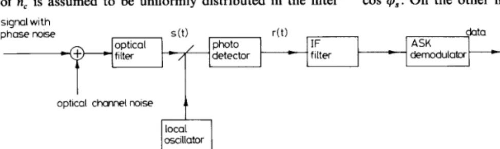
The system block diagram of the optical ASK receiver in a noisy optical channel is shown in Fig. 1. For simplicity and because the spontaneous noises are randomly gener- ated with spectral distributions usually much wider than a coherent signal, we assume that the optical channel noise is white Gaussian. The optical filter at the input of the receiver is used to limit the noise spectrum. After passing through the optical filter, the signal and channel noise are incident on the photodetector (PD) to produce photocurrents. A bandpass filter is used to eliminate outside-of-band noise and an ASK demodulator is employed to recover the baseband signal.
2.1 Time domain analysis
A heterodyne detection optical receiver is polarisation- sensitive. Here we assume the signal and LO polarisa- tions are well controlled to be the same and consider the part of channel noises along the same polarisation as the signal and LO. Let the optical filter be centred at the signal frequency with bandwidth BW, which is assumed to be sufficiently wide to pass the signal undistorted. The output of the optical filter can be written as
s(t) = b , J ( 2 ~ , ) cos (w,t
+
4,it))
+
n, (1) where P,,
w,, and +,(t) are the power, angular frequency, and phase noise of the signal, nc is the part of opticallyfiltered channel noise with the same polarisation as the signal, and bk takes the values of '1' or
'U.
The spectrum of n, is assumed to be uniformly distributed in the filter sianal withwhere RnAz), R,(z), &k(T), RAT), respectively, represent the
autocorrelation functions of n i , cos (wIF t
+
4,),
bk , and cos 4,. On the other hand the crosscorrelation functionphoto IF
detector = filter
ASK demodulatw
t
optical channei mise local oscillator
Fig. 1 System block diagram of an optical ASK receiver in the presence of optical channel noise
passband with two-sided spectral density N,/2. We can expand n, at the carrier frequency as [ 141
n, = ni cos w,t
+
n,, sin w,t ( 2 )where ni and n4 are independent Gaussian processes with uniform spectral density N , within baseband bandwidth B W O . The LO output is expressed as
Jw)
= J(2PL) cos (w,t+
( 3 )where P , , we, and
4,
are the power, angular frequency and phase noise of LO. To simplify the notation, the time dependence of phase noises is dropped if it is irrelevant. The PD output current can be written asr(t) = R [ s ( t )
+
ut)]'
+
nsh(44
where R is the responsivity of the P D and nsh is the shot noise. By neglecting the optical frequency terms, whch are irresponsive to the PD and the low frequency terms,
r(t) can be expressed as an intermediate frequency (IF)
signal plus four noises, given by r(t) = 2bk RJ(Ps p L ) cos ( W I F
+
4)
ni"
+ n:+
n,+
n,+
nSk (4b) 2+ R where
n, = Rbk,/(2PS)(ni cos
4,
- n,, sin4,)
nL = R J ( 2 P d n i COS (WIF t+
4,)
( 5 )
-
nq sin ( w I F t+ 431
(6) Here4
=4,
-
4,
is the phase difference between the signal and LO and wIF = w, - w, is the intermediate angular frequency. For simplicity the circuit noise is neglected. The first term of eqn. 4b denotes the I F signal, whereas the second term is the self-product of channel noise which is a result of the incident channel noise power on the PD. The third results from the cross- product of the signal and channel noise, denoted as signal-channel noise n,; the fourth term is the cross- product of the LO and channel noise, denoted as LO-channel noise n,; and the last term is the P D shot noise n,,, which is a consequence of the quantum nature of the photodetection process. For a system with appropriate bit error probability, P , and P , should be much larger than n? and n,". Thus we neglect the term (n?
+
n,")/2 in the following discussion.At first we investigate the statistical properties of n, and n,. The autocorrelation functions of n, and n,, denoted as RnL(7) and R,,,(z), are given by (see Section 7)
RnL(7) = 4R'PL R n X 7 M 7 ) (7)
R&) = 4R'Ps Rbk(r)Rni(7)RB(7) (8)
334
of n, and n, is formulated as [see Section 71
R,(z) = 0 (9)
Hence n, and n, are uncorrelated.
n,
.
By definition we haveLet P(n,) denote the probability density function of
P(nJ =
Krn
P(nLI
4L)P(4L)d 4 L
(10) where P(nLI
4,)
denotes the conditional probability of n, given4,.
For a fixed I$,, we can express nL by an envelope function asnL = u COS ( w I F t
+
4,
+
0) ( 1 1 ) Because n, and n4 are independent Gaussian random variables, thus U is the well known Rayleigh distributionwith variance o:, given by
0; = 2R2PLu,' (12)
where 0,' is the variance of n, and n,, which is equal to
N , B W , . 0," is also the power of spontaneous noises
which polarise along the signal polarisation. And 0 is uniformly distributed within [--n, n] [lS]. After some mathematical manipulations, we can prove that the con- ditional probability is Gaussian distributed and, most importantly, independent of
4,
as [ 151= W L ) (13)
Thus we conclude that n, is a zero mean Gaussian vari- able with variance 0;. Similarly, based on a conditional
probability scheme we can again prove that n, is a zero mean Gaussian variable with variance 0,' as
of = 2bk R'P, 0,' (14)
Since n, and n, are Gaussian distributed and uncor- related, they are also mutually independent [ 141. Because the P D shot noise n,,, depends on the incident optical power only, it is independent of
4,
and4,.
Practically the channel noise power is much smaller than the signal and LO, nSh is therefore independent of n, and n4. Thus nsh is independent of both n, and n,. We thus treat the three noises n,, n,, and nSh as mutually independent Gaussian noises.2.2 Spectral analysis
We proceed to examine the power spectral densities (PSD) of the noises and use this information to further investigate their respective impact on the receiver per- formance. The PSDs of n, and n,,, which are identical, are baseband distributed with bandwidth B WO and density
N , , given by
L L
= 0 elsewhere (15)
The PSDs of cos ( w I F t
+
$L) and sin ( w I F t+
4L)
aregiven by [ 3 ]
(16) where B, denotes the LO laser linewidth in terms of Hz and
fiF
is the intermediate frequency. Eqn. 16 indicates that S , ( f ) is composed of two Lorentzian distributions centered at + f r F . From eqn. 7 we can obtain the PSD ofn, as
S n L ( f ) = 4R2PL
sndf)
*
S u U ) (17) where an asterisk denotes convolution. Mathematically we expect that Sn,(f) has its maximum at + f I F andspreads over BW,, if BWo & B , . From eqns. 15-17, S n L ( f ) is readily calculated as
-
tan-l(f
- f I F - B w O / 2 )BL.12
On the other hand, the PSDs of cos
4,
and sin4,
are again the same, given by [ 3 ](19) where B, is the signal laser linewidth in terms of Hz. It is easy to see that S , ( f ) is Lorentzian distributed at base- band. Referring to eqn. 8 the PSD of n, is readily obtained as
s n s ( f ) = 4 R 2 P s S b k ( f )
*
sndf)
*
s & f )
2 R 2 P , N w
f
+
BWOP-
- x S b k ( f )
*
[tan-1( B ~ 2)
where & ( f ) is the PSD of b, , given as
where S ( f ) is the Delta function and T is the bit dura- tion.
We assume that the PD shot noise is a white Gaussian process with PSD as
s n , h ( f ) = eR(P,
+
p,) --CO < f < CO (22) where e is the electron charge, equal to 1.6 x Coulomb. Since P , and P , are assumed to be much larger than the channel noise power so that the shot noise owing to channel noise is neglected in eqn. 22. An illus-IEE PROCEEDINGS, Vol. 137, P t . J , N o . 5, O C T O B E R 1990
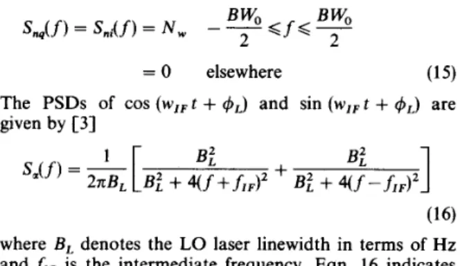
trative example of the PSD of the three noises is shown in Fig. 2. In this and the following examples we consider an optical ASK system with bit rate (Br) = 140 Mbit/s, P , = 1 mW, BL = B, = 10 MHz, and R = 1 A/W. The Figure shows that n, is a baseband noise which depends
X1622
76t
S",Cf)-2000 -1500 -1000 -500 0 500 1000 1500 2000 frequency,MHZ
Fig. 2 Illustrative example of PSD for the three noises
P, = -7 dBm; BW, = 1 GHz; f,, = 700 MHz; N , = 3e W/Hz
on the channel noise and signal phase noise while n, is a bandpass noise centered at k f I F and depends on the
channel noise and LO phase noise. Since the signal locates at + f r F , nL is expected to be a critical noise to the
system. However, depending on the bandwidth of the optical filter and the received signal power, n, may also degrade the system performance.
We place a linear bandpass filter (BPF) after the PD to eliminate outside-of-band noise. It is well known that a linear transformation of Gaussian random variable yields Gaussian random variables [ 1 4 ] . Since the three noises are independent Gaussian random variables, they are expected to be independently Gaussian distributed at the BPF output. Thus we can calculate their variance at the BPF output through spectral domain. For simplicity we take the BPF as an ideal rectangular filter centered at
IF
with bandwidth BW, and transfer functionL L
= 0 elsewhere (23)
After passing through the BPF, the noise powers of n,,
n,, and nsh , denoted as N , , N , , and N,, , are obtained by integrating their PSD within the passband of BPF, given, respectively, as I IF + B W d 2 IF + B W e / 2 NL =
j
S n L ( f ) d f +j
S n L ( f ) df (24) I ~ F - B W d 2 - . f l ~ - B W d 2 f l F + B W e / 2 - f r ~ + B W d 2 ~s =j
s n s ( f ) d f +j
SflXf) df (25) I I F - B W e / 2 IF- B W 4 2 (26) N,, = 2eR(P,+
PL)BWeN , , N,
,
and N,, not only denote the filtered noise power but also represent the variance of the three Gaussian noises which are critical factors to evaluate the bit error probability. Figs. 3 and 4 illustrate the dependence of N , and N , on the optical filter bandwidth. The rapid increase of N , as SWo increases toward 4fIF is a result of spectrum folding of Sn,(f). This results in a factor of 2increase in N , . The same phenomenon occurs for N , . However, the increase of N , is caused by the extension of
the baseband spectrum Sn,(
f)
toward the BPF passband as BW, increases toward2fIiF.
Also note that N , is essen- tially zero for small BW, since there is no noise power within the BPF passband.0
omitted. For N , = 10 e, N , dominates and S N R suffers about 3 dB decrease as BW, increases toward 4 I F
because of band folding of S,,(f). In this case a narrow band optical filter is helpful to increase S N R .
,
_ -
1 34l
I 0 2 4 6 8 10 12 14 16 18 20 SW, IBW, Fig. 3 BW, = 240 MHz; N , = e W/Hz N , as a function of BW,/BW, Fig. 4 BW, = 240 MHz; N , = e W/Hz; P , = -50 dBm N , as a function of BW,/BW, 3 DiscussionWe assume that BW, is wide enough to pass the signal undistorted in the presence of phase noise. Thus at the BPF output the problem can be formulated as a binary AM signal plus three independent Gaussian noises. With channel noise, the IF signal to noise ratio is written as
2R2P, P ,
S N R =
NL
+
N ,+
N,,Here we consider two cases. First, let the optical channel noise be induced by repeater optical amplifiers so that the received signal power P , is much smaller than P , . In this case it is clear that N , $ N , . For N , = 0.1 e (note that the unit of N , is W/Hz, is different from that of e), because N,, dominates the noise terms so that S N R is nearly independent of BW, as shown in Fig. 5. Thus the optical filter has little benefit to the system which can be
336 101 0 2 ' 4 6 8 10 12 14 16 18 20 BWolBWe Fig. 5 vaiues of N , EW, = 240 MHz; f,, = 700 MHz; P , = -50 dBm
Relation between S N R and optical filter bandwidth for several
Secondly, we are concerned with the case where the optical channel noise is introduced by an optical pre- amplifer. For example, a fibre Raman amplifier (FRA) can be used to extend transmission distance. Since the spontaneous emission noise induced by an FRA is a wideband noise and proportional to the amplifier gain in the linear gain region [16], we can model the output noise PSD of an FRA as an equivalent input noise PSD amplified by the FRA. Thus the output noise PSD and signal power are written as
N , = G N , (28)
P , = G P ,
(29)
where N o , P , , and G express the equivalent input noise PSD, the input signal power, and the gain of the FRA, respectively.
The relation between S N R and BW, in the presence of an optical preamplifier is shown in Fig. 6. We observe
251
235t
23 22 q,2 21 5- 21-
2 0 5 - 201 0 2 4 6 8 10 12 14 16 18 20 BW,IBWe Fig. 6 amplifier gains BW, = 240 MHz; N o = 0.1 e W/Hz; f,, = 700 MHz; P, = -60 dBmRelation between S N R and opticalfilter bandwidthfor two pre-
that a narrow band optical filter can eliminate N , and prevent band folding of SnL(
f )
so as to increase S N R . The dependence of S N R on G is depicted in Fig.7.
For agiven P , and N o . It is easy to see that the I F signal power and N , are proportional to G because they are, respectively, proportional to P , and N , . On the other hand, since S , , ( f ) is proportional to both P , and N , , N , is proportional to G 2 while N,, is proportional to
33 3 2
-
- SW, SW, arnplifiergain,dB Fig. 7 BW, = 240 MHz; N o = 0.2 e W/Hz; f,, = 700 MHz; P, = -50 dBmS N R as a function of preampli$er gain
-111 , , , , , , , , , , 10 0 1 2 3 4 5 6 7 8 9 10 N , le Fig. 8 BW, = 240 MHz; P , = -50 dBm; f,, = 700 MHz Degradation of P , against channel noise PSD
P ,
+
G P , . If the optical filter bandwidth is narrow enough, for example a narrow band tunable optical filter is employed, n, can be completely filtered by the BPF. In this case only N , and N,, are significant. When G is small, N,, dominates because e % N , and P , % G P , sothat the noise power is nearly independent of G. As a result, SNR increases with G. When G is large enough, N, dominates so that S N R increases little with G . On the
IEE PROCEEDINGS, Vol. 137, P t . J , N o . 5, OCTOBER 1990
other hand, if a wide bandwidth optical filter is used, the contribution of n, should be taken into account. When G is small, S N R increases with G. Because of the G 2 depen- dence of N , we can expect that N , will dominate the
t
10’’\ \ \&\
-60 -58 -56 - 5 4\ #
-52\
-50, \
- 4 0\,
Ps,dBrn Fig. 9 BW, = 240 MHz; P , = -50 dBm; f,, = 700 MHz P , as a function of P , for U+ = 0noise contribution if G is large enough and S N R decreases as G increases. Consequently there exists an optimum amplifier gain to achieve maximum S N R as shown in Fig. 7. Because of the
G2
dependence of N , , a narrow bandwidth optical filter should be used to elimi- nate this noise when the preamplifier gain is large.We use a synchronous ASK demodulator after the I F filter to recover the baseband data. Here we consider an ideal case where the I F carrier can be tracked from the signal and used to reproduce the baseband waveform. The bit error probability P , of such a synchronous detector had been circumstantially derived in Reference 5 which can be expressed as a function of IF S N R . For simplicity we set the threshold at the middle of ‘0’ and ‘l’, thus P , can be written as
p , =
1
7c [ ~ ~ e - x z e - ~ z dy d xwhere
g ( x ) = J(SNR)[O.5 - COS (J(2)0+ x)] (31) and 0:is the variance of
4.
Fig. 8 illustrates the bit errorprobability with respect to N,. It is seen that the bit error rate degrades seriously when N , is large, particu- larly for small U @ . We can use a narrower bandwidth
optical filter to reduce the impact of the channel noise but cannot completely eliminate it since the LO-channel noise possesses the same spectrum as the I F signal.
The degradation of P , from shot noise limited curve owing to channel noise is presented in Fig. 9. We see that there is about 3 dB degradation from the shot noise limit for N , = e. Thus the parameter e is a good parameter to estimate the degradation of P , in the presence of optical channel noise.
4 Conclusion
We have theoretically analysed the performance of an optical ASK receiver in the presence of optical channel noise. The channel noise can come from repeater optical amplifiers or receiver preamplifiers. Two new noises, characterised as signal-channel noise and LO-channel noise, which result from the multiplication of channel noise with the signal and local oscillator lasers in the optical-to-electrical conversion process, are introduced. The statistical studies show that these noises are indepen- dent and Gaussian distributed, and are independent of the shot noise. Through spectral analysis we have made clear the effect of optical filter bandwidth on the system performance. The results show that a narrow band optical filter is necessary to suppress channel noise if strong channel noise is present, while it is less useful if the channel noise is weak since shot noise dominates. We also find that there exists an optimum preamplifier gain which results in a maximum signal-to-noise ratio if wide bandwidth optical filter is used. The examples reveal that strong channel noise can seriously degrade the system performance. However, it can be partly relieved by using a narrow bandwidth optical filter.
5 Acknowledgment
The authors would like to express their sincere gratitude to Prof. Hen-Wai Tsao for his helpful discussions. This work is supported by the National Science Council of the Republic of China.
6 References
1 OKOSHI, T. : ‘Recent progress in heterodyne/coherent optical-fiber communications’, IEEE J. Lightwave Technol., 1984, LT-2, pp. 2 LINKE, R. A.: ‘High-capacity coherent lightwave systems’, IEEE J. 3 SALZ, J.: ‘Coherent lightwave communications’, A T & T Tech. J., 4 GARRETT, I., and JACOBSON, G.: ‘Theoretical analysis of het- erodyne optical receivers for transmission systems using (semiconductor) lasers with nonnegligible linewidth’, IEEE J. Light- wave Technol., 1986, LT-4, pp. 323-334
5 FRANZ, J.: ‘Evaluation of the probability density function and bit error rate in coherent optical transmission systems including laser phase noise and additive Gaussian noise’, J. Opt. Comm., 1985, 6, 6 KAZOVSKY, L. G., MEISSNER, P., and PATZAK, E.: ‘ASK multiport homodyne receivers’, IEEE J. Lightwave Technol., 1987, 7 MOCHIZUKI, K.: ‘Optical fiber transmission systems using stimu- lated Raman scattering: theory’, IEEE J. Lightwave Technol., 1985, 8 LIN, C.: ‘Nonlinear optics in fibers for fiber measurements and special device functions’, IEEE J . Lightwave Technol., 1986, LT-4, 341-345 Lightwave Technol., 1988,6, pp. 175G1769 1985,64, pp. 2153-2209 pp. 51-58 LT-5, pp. 770-791 LT-3, pp. 688494 pp. 1103-1115 338 ~ 9 10 11 12 13 14 15 16 7
SIMON, J.C. : ‘Semiconductor laser amplifier for single mode optical fiber communications’, J. Opt. Comm., 1984,4, pp. 5 1 4 2
O’MAHONY, M.J. : ‘Semiconductor laser optical amplifiers for use in future fiber systems’, IEEE J . Lightwaoe Technol., 1988, 6, pp. AOKI, Y.: ‘Properties of fiber Raman amplifiers and their applica- bility to digital optical communication systems’, IEEE J . Lightwave Technol., 1988,6, pp. 1225-1239
JOYCE, G.R., LANZISERA, V., and OLSHANSKY, R.: ‘Improved sensitivity of 60 video channel FM-SCM receiver with semicon- ductor optical preamplifier’, Electron. Lett., 1989,25, pp. 499-500 OLSSON, N.A.: ‘Lightwave systems with optical amplifiers’, IEEE J. Lightwave Technol., 1989,7, pp. 1071-1082
DAVENPORT, W.B., and ROOT, W.L.: ‘An introduction to the theory of random signals and noise’ (McGraw-Hill, New York, 1958)
PAPOULIS, A.: ‘Probability, random variables, and stochastic process’ (McGraw-Hill, New York, 1965)
KAO, M.S., and WU, J.: ‘Signal and noise in a coherent optical communication system using Raman amplifier’, Microwave and Opt. Technol. Lett., 1989, 2, pp. 1G13
531-544
Appendix
where R,i(z), R&), R E O S ( ~ ) , and RSin(7), respectively, represent the auto-correlation functions of ni, n, ,
cos ( w I F t
+
4L),
and sin (wIF t+
4L).
It is easy to prove that R,i(z) = R,,(z) [14] and RCOS(7) = R,,,(z) [ 3 ] , thus we can further simplify eqn. 32 asRnL(7) = 4R2PL RnX7)RAz) (34)
where for simplicity we use &(z) to represent &(T) and Rsin(7). In a similar manner we can obtain the auto- correlation function of n, , R,,(T), as
R d z ) = 4R’P.v R,AT)Rni(t)RB(7) (35)
where R,,(z) is the auto-correlation function of b, where
R&z) is that the cos
4,
and sin4,.
We next examine the relation between nL and n,. The crosscorrelation function of nL and n, is formulated as
~ ( r ) = E C ~nS(t ,
+
41
= 2 R Z b k , / ( P s P L ) x ECnd+ho+
4
cos ( W I F t+
4 L W
x cos4,(t
+
z)+
n,(t)nq(t+
z) - ni(t)nq(t+
7) COS ( w I F t+ 4dt))
x sin ( w I F t+
4dt))
sin4,(t
+
z) x sin4,(t
+
z) - n,(t)ndt+
z) x sin ( w I F t+
4L(t))
COSd,(t
+
T)] (36)In a heterodyne coherent system, ni, nq,
4L
and4,
are mutually independent. Using the zero mean property ofni and n,, the last two terms diminished and eqn. 36 can be rewritten as
Since
4L
and4,
are random Brownian motions [3], the expectation values of cos4,(t
+
T ) and sin +,(t+
z) arezero. Thus we have