Design of Cofferdam for Intake Structure at
Nanhua Reservoir Sediment Sluicing Tunnel
Shang-Yao Lien, Chun-Chieh Liu, Min-Chen Lee, Hsien-Chung Chiang and Chun-Yi Liao
Abstract
In order to slow down Nanhua Reservoir siltation and to extend the reservoir lifetime, the Nanhua reservoir sediment sluicing tunnel project was proposed in 2013. The tunnel is located at the upstream of the Nanhua dam on the right bank, and it consists of the intake structure, the control chamber, sluicing tunnel, and outlet structure. The total length of the tunnel is 1481m. The high water level of Nanhua Reservoir is at EL180m, and the bottom of the intake structure is at EL. 135 m. In order to construct the intake structure, a temporary cofferdam was designed to retain the water. Some parts of the cofferdam will be demolished after the intake structure was completed.
The cofferdam consists of a semicircle weir and two abutments. Thickness of the semicircle weir is 4~5 m and abutments is 7 m. Top elevation of the cofferdam is at EL. 182.5 m. Cofferdam analysis should consider the effects of high water pressure, earthquake and temperature stress on the concrete. 3D finite element analysis software ABAQUS-TM was used to analyze the cofferdam. According to the analysis results, over-tensile stress appears on the outer side of semicircle weir, the junction of the semicircle weir and two abutments. Meanwhile, a comprehensive consideration is proposed via designing minimum steel bars to increase tensile strength of the cofferdam. Keywords: Sediment sluicing tunnel, Nanhua Reservoir, cofferdam
1 Project introduction
Nanhua Reservoir was completed in 1993 The sediment sluicing tunnel located at the upstream of the Nanhua dam on the right bank consists of the intake structure, the control chamber, sluicing tunnel, and outlet structure.
The temporary cofferdam was designed to retain the water thus the construction work can be conducted at the dry side. The plan view of the project is shown in Fig 1.
The total length of the tunnel is 1,410.85m with a constant slope of 1.847%. The designed discharge rate of the sediment sluicing tunnel is 1,000 cms, The typical cross section of the sluicing tunnel is horse shoe shape with a clearance width and height of 9.5m. The thickness of the reinforced concrete lining is 80cm as shown in Fig 2.
Fig.1 Site plan of sediment sluicing tunnel
Fig.2 Standard profile of sediment slucing tunnel
Intake structure Control Chamber A cc ess Tu n n el( 59 8 m ) Access Road(937m) Outlet structure Filling Area B Nanhua Reservoir Filling Area A Coffer dam
9.5m
0.8m
0.8m
9.5m
0.8m
0.8m
350 kg/cm
2concrete
lining
Waterproof
membrane
350 kg/cm2reinforced concrete lining2 Introduction of cofferdam
The top elevation of the cofferdam is at EL. 182.5 m and the bottom of the excavation side is at EL. 135 m. Therefore, the maximum water pressure difference is 47.5 m. The cofferdam consists of a semicircle weir and two abutments. Thickness of the semicircle weir is 4~5 m and abutments is 7 m. The semicircle weir and two abutments are formed by two rows of φ1.25 m steel pipe pile and the concrete is filled the gap between the steel pipe piles (See Fig.3 & Fig.4). Since the cofferdam is a temporary structure, the semicircle weir and the two abutments above EL170 will be demolished after the completion of the intake structure.
Fig.3 Plan view of the cofferdam
Fig.4 Longitudinal profile of the cofferdam
7 .0 4.0 5 .0 5 .0 Abutment Semicircle Weir Core concrete 1.25m steel pipe piles
1.25m steel pipe piles HWL=EL.180m
EL.135.0
EL.125.0
EL.182.5
Core concrete
Sediment Level EL.156m(2015)
10m 47.5m
At present, the construction of the cofferdam has been completed, and the construction of the intake structure is carried out inside the cofferdam as shown in Fig 5
Fig 5 Construction photos of cofferdam (2019.01)
3 Design of the cofferdam
The cofferdam is a composite structure thus the behavior of the structure has to consider the arching effect of the semicircle weir and temperature load of the massive concrete. 3D finite element analysis software ABAQUS-TM was used to analyze the structure. Load combinations of the cofferdam is shown in Tab 1.
Tab. 1 Load combinations of structural analysis
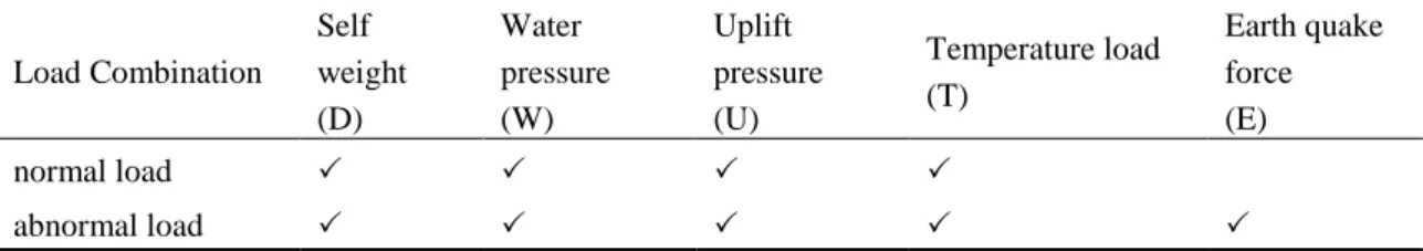
Load Combination Self weight (D) Water pressure (W) Uplift pressure (U) Temperature load (T) Earth quake force (E) normal load abnormal load
According to the numerical analysis results, the tensile stress of the core concrete are shown in Fig. 6 and Fig. 7 respectively. Under the condition of abnormal load, the analysis results show that the over-tensile stress appears on the outer side of semicircle weir and the junction of the semicircle weir and two abutments (The gray area in Fig.6 & Fig7)
Fig.7 Tensile stress distribution of the abutment under extreme load combination
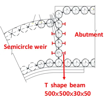
According to the analysis results, the steel bars are designed to increase tensile strength of the cofferdam. The reinforced concrete ring beam is placed at the range of EL. 179~182.5 m of the semicircular wire to increase tensile capacity. as shown in Fig. 8. In addition, T-beam are installed at the junction of the semicircle weir and two abutments, as shown in Fig. 9.
Fig.8 Schematic diagram of cofferdam reinforcement EL182.5~170 Under EL170 臨時部分 永久保留 EL.179~182.5m配置環樑鋼筋 EL179~EL170交界處配置鋼筋 EL170 EL182.5
Steel bars area
Permanent part
Temporary part
Abutment
semicircle weir
臨時部分 永久保留 EL.179~182.5m配置環樑鋼筋 EL179~EL170交界處配置鋼筋 EL170 EL182.5Fig.9 T-beam at the junction of the semicircle weir and two abutments
Because this cofferdam is a high-risk temporary structure, in order to reduce the possibility of large-scale deformation or damage under earthquakes. The horizontal H beam support system is added inside the cofferdam at elevations of 180 m, 167.5 m and 155 m, as shown in Fig. 9.
These horizontal supports provide additional support of the cofferdam. The horizontal H beam support system is an external structure, which can be found immediately when abnormal deformation occurs. And the monitoring device can be installed to assist in detecting abnormal deformation and early warning.
Fig Horizontal support system inside the cofferdam
T shape beam
500×500×30×50
Abutment
Semicircle weir
EL.180m Horizontal support Waling Horizontal supportstrain gauge (at EL180,167.5, 155)
waling
EL.167.5m
4 Conclusions
After the completion of the project, it can slow down the siltation and prolong the lifetime of the Nanhua Reservoir. In addition, it can also increase the flood control capacity of the reservoir, reduce the turbidity of the raw water of the reservoir during the typhoon period, and it is expected to achieve the ideal goal of sustainable use of water resources facilities.
The design of the cofferdam shall take into account the feasibility of future demolition. The effects of high water pressure, earthquake and temperature stress on the structure of the cofferdam should also be considered. For comprehensive analysis considerations, steel bars shall be designed and placed on the top of the cofferdam to improve the tensile capacity of the cofferdam structure.
References
Sinotech Engineering Consultants,Ltd (2014). Sediment sluicing tunnel project at Nanhua reservoir- structure analysis of the coffer dam.
Sinotech Engineering Consultants,Ltd (2014). Nan-hua sediment sluicing tunnel project at Nanhua Reservoir - the control chamber excavation analysis[R].
South Region Water Resources Office, WRA, MOEA (2013). The Hydraulic Model Test Report for the Sediment Sluicing Tunnel Project of Nanhua Reservoir.
South Region Water Resources Office, WRA, MOEA (2013). The Basic Design Report of the Sediment Sluicing Tunnel Project of Nanhua Reservoir.
Authors
Chun-Yi Liao (Corresponding Author) Min-Chen Lee
Hsien-Chung Chiang
Sinotech Engineering Consultants Limited, Taipei, Taiwan, ROC Email: cyliao5783@mail.sinotech.com.tw.
Shang-Yao Lien Chun-Chieh Liu