www.elsevier.com / locate / mee
A
pplication of soft landing to the process control of chemical
mechanical polishing
a b ,
*
cJian-Bin Chiu , Cheng-Ching Yu
, Shih-Haur Shen
a
Department of Chemical Engineering, National Taiwan University of Science and Technology, Taipei 106-07, Taiwan
b
Department of Chemical Engineering, National Taiwan University, Taipei 106-17, Taiwan
c
Applied Materials Taiwan Ltd., Hsin-Chu 300, Taiwan Received 20 September 2002; accepted 20 October 2002
Abstract
In chemical mechanical polishing (CMP), a two-stage polishing strategy is often employed. A high removal rate (RR) is set at the initial stage, then a lower RR is employed to remove residual metal and extended to the over-polish stage. An analogy between the soft landing of a spacecraft and CMP operation is established and the CMP operation can be viewed as a minimum-time optimal control problem. Measurement uncertainties prevent direct implementation of bang-bang control law for the entire polishing process. Thus, a two-stage CMP operation procedure is devised to ensure robust operation while maintaining a high throughput.
2002 Elsevier Science B.V. All rights reserved.
Keywords: Soft landing; Minimum time problem; Chemical mechanical polishing; Damascene; STI process control
1
. Introduction
The complexity of current microelectronic devices demands global planarity at different metalliza-tion levels. Chemical mechanical polishing (CMP) has the capability of achieving such stringent requirements over a step height of several microns. Since the introduction of the new technology in the 80s, the CMP provides advantages of defect reduction, wide windows for etching and lithography and yield improvement [5,6,13]. Combining the chemical reactions and mechanical force abrasion, the wafer surface can be polished to achieve global planarity. Despite recent advances in CMP, some manufacturing concerns associated with successful implementation of CMP remain to be overcome [2,3,5,7,9,13]. The physical interactions among the wafer, slurry, and pad make the copper CMP very sensitive to operating conditions. If the CMP is operated in an undesirable region, it may lead to
*Corresponding author. Tel.: 1886-2-3365-1759; fax: 1886-2-2362-3040.
E-mail address: [email protected](C.-C. Yu).
0167-9317 / 02 / $ – see front matter 2002 Elsevier Science B.V. All rights reserved. doi:10.1016 / S0167-9317(02)01024-9
non-uniformity, surface damage and / or degradation in the removal rate (RR). Recently chemical mechanical polishing (CMP) has become the standard technique in copper damascene technology [4,5,9,13].
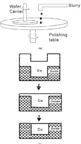
CMP causes material removal by rotating a polishing pad against the wafer in the presence of liquid slurry. In practice, the silicon wafer is held face down and a normal load is applied while the polishing pad, mounted to a rigid turntable, rotates beneath the wafer (Fig. 1). Typically, the wafer is also rotated with a similar speed and material removal occurs due to the contact between the pad and wafer, and the chemical interaction with the slurry [2,4,10,12,13]. The mechanisms of material removal in CMP are related to both chemical and mechanical effects [2,4,7].
Most of the research work on CMP is focused on detailed removal mechanisms (e.g., chemical and / or mechanical factors) and the slurry chemistry [2,4,10,12]. Much less work has been done on the operational aspects of CMP, especially the process control side of CMP operation. One of the most important variables: the setting of the removal rate for the planarization process, is studied in this work. The reminder of this paper is organized as follows. An analogy between the soft landing of a spacecraft and the CMP process is illustrated in Section 2. The minimum time optimal control problem is solved in Section 3. Then, constraints and uncertainty issues are also addressed and, subsequently, a realistic procedure is proposed for CMP process followed by the conclusion.
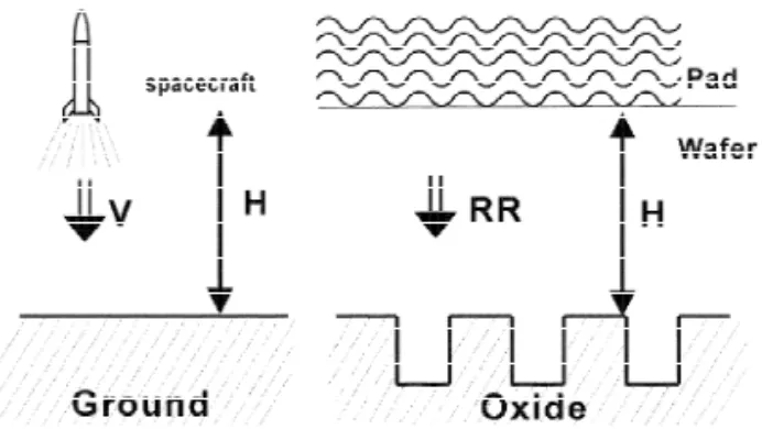
Fig. 2. Analogy between landing a spacecraft and CMP copper removal.
2
. Analogy
Soft landing is a control strategy originally applied to the landing of a spacecraft to land on a hard surface and, at the instant of landing, the vertical velocity of the vehicle is reduced to zero (Fig. 2). The objective is to minimize the landing time while ensuring a safe landing without damaging the vehicle [1,8,11]. A similar situation is encountered in the operation of CMP. First, we treat the oxide surface as the landing surface, the polishing pad as a fly vehicle, and the removal rate as the vertical velocity. When the polisher reaches the endpoint (oxide), it can be visualized as the fly vehicle contacting the heavenly body surface (Fig. 2). Typically, the damage, dishing, is assumed to be proportional to the removal rate [7]. Therefore, the damage can be reduced by a smaller RR while minimizing the polish time. In other words, we would like to minimize the damage to the wafer while maintaining a high throughput.
Therefore, the CMP operation can be formulated as an optimal control problem with the following variables: H, the thickness of copper to be removed (including the over-polish thickness) (e.g., the altitude before landing); RR, the removal rate (e.g., the vertical velocity of the spacecraft); a, acceleration of the removal rate (e.g., the net acceleration or deceleration of the spacecraft). The equations describing the copper removal can be expressed as:
dH ] 5 2 RR (1) dt dRR ]] 5 a (2) dt
with the following initial conditions.
H(0) 5 H0 and RR(0) 5 RR0 (3)
The constraints in the acceleration (control) are also applied.
2 amax# a # amax (4)
Similar to the soft landing of a spacecraft, an analytical solution to the optimal control problem can be derived.
3
. CMP soft landing
3
.1. General solution
Let us use a state space equation to represent the CMP soft landing problem with x 5 H, x 5 RR,1 2
and u 5 a. Thus, we have:
~ x1 0 2 1 x1 0 5 1 u 5 Ax 1 Bu (5)
F G F
x~ 0 0GF G F G
x 1 2 2 with 2 amax# u # amax (6)This is a double integrator process and the control problem is to find u(t) to bring the system to
x(t ) 5 0f (7)
in minimum time. In optimal control literature, that is a minimum-time problem [1,8,11]. The objective function is simply:
tf tf
J 5
E
L dt 5E
1 ? dt (8)0 0
Following Bryson and Ho [1], first, define the variational Hamiltonian
T T
H* 5l (Ax 1 Bu) 1 L 5l (Ax 1 Bu) 1 1 (9)
wherel(t) is the Lagrange multiplier. To minimize H* with respect to u by taking the constraints Eq. (6) into account, we have the following bang-bang control:
T amax, l B , 0
u(t) 5
H
T (10)2 amax, l B . 0 T
The quantity l B 5l2 is called the switching function. The transversality condition with the boundary condition Eq. (7) yields:
T l (t )Bu(t ) 5f f l2(t )u(t ) 5 2 1f f (11) That implies: 1 /amax, u 5 2 amax l2(t ) 5f
H
2 1 /a (12) , u 5 a max maxThe Euler–Lagrange equation is of the following form:
≠H* T T ~ ]] l 5 2 ≠x 5 2l A (13) Specifically, we have: ~ ~ l15 0 and l25 2l1 (14)
Eq. (14) reveals the switching function is a linear function of time, it can change sign at most once. Therefore, we can locate the switching curve in state space (in terms of x and x ) going back in time1 2 from t with u 5 2 af max or u 5 2 amax. Integrating Eq. (5) from t , one obtains:f
2
x /(2a2 max), u 5 2 amax
x 51
H
2 (15)2 x /(2a2 max), u 5 amax
Back to the CMP notation with the boundary condition for the end point
H(t ) 5 0f and RR(t ) 5 0f (16)
the switching curve becomes: RR RRu u
]]]
H 5 (17)
2amax
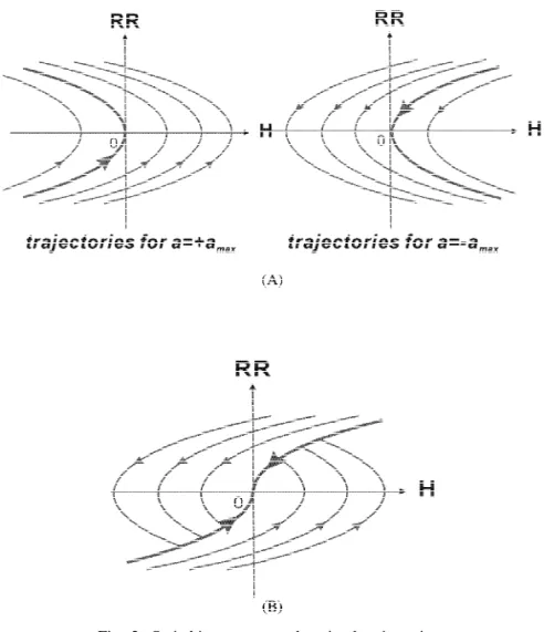
The switching curve is made up of two parabolas as shown in Fig. 3. Fig. 3 shows typical trajectories for u 5 2 amax or u 5 amax, respectively, and the switching curve is shown as the thick solid line. If
the initial condition is not on the switching curve, we must determine the control u. Fig. 3B clearly indicates that, above the switching curve, we have u 5 2 amax, and below the curve, we have u 5 amax. For CMP, we are limited to the first quadrant and the control law becomes:
2
2 amax, H # RR /(2amax)
a 5
H
2 (18)1 amax, H . RR /(2amax)
˚
Generally, a polishing process starts with a non-zero H (e.g., H 5 8000 A) and RR 5 0 and,0 0 0 therefore, the initial condition is located at the positive side of x-axis (e.g., Fig. 3B). Initially, the removal rate increases with the acceleration a 5 amax (following a trajectory in Fig. 3B). When the trajectory meets the switching curve (Eq. (17)), the removal rate decelerates with a 5 2 amax, following the path along the switching curve, and lands on the origin (i.e., Eq. (16)). Integrating the governing state space equations (Eqs. (1) and (2)) with the control law of Eq. (18), we can find the following conditions at switching point (Eq. (17)):
Hsw5 H / 20 (19) ]] RRsw5 a
œ
maxH0 (20) ]]] tsw5 H /aœ
0 max (21) ]]] t 5 2 H /afœ
0 max (22)where the subscript sw denotes the switching point.
3
.2. Possible constraints
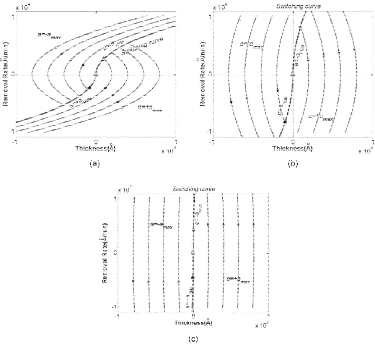
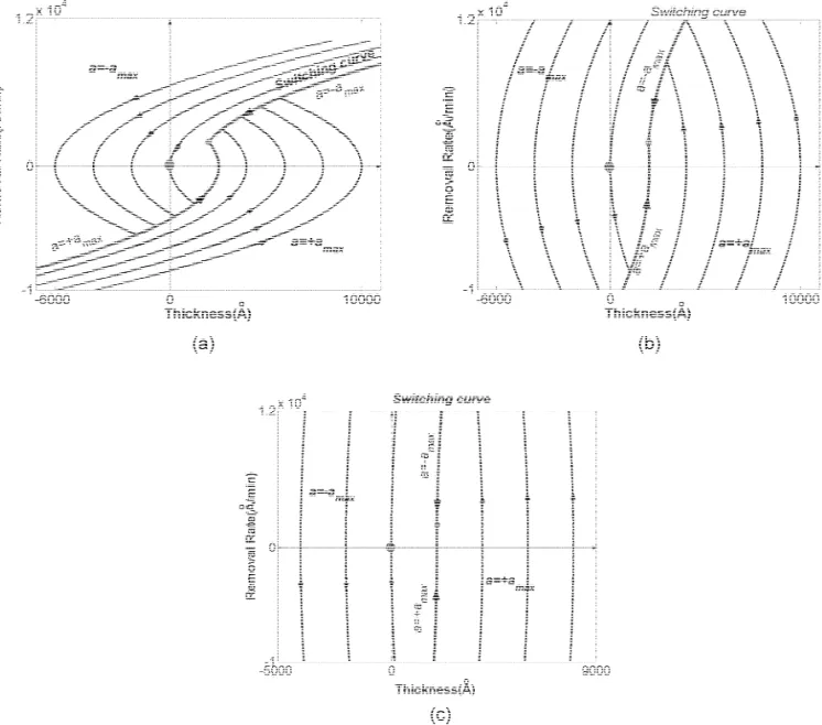
Unlike the landing of a heavy spacecraft, rapid acceleration can be achieved by a CMP motor. Let us explore how the shapes of switching curves and typical paths change as amax varies. The maximum
2 2 2
˚ ˚ ˚
accelerations of 3600 A / min , 36 000 A / min , and 360 000 A / min correspond to reaching
˚
RR 5 9000 A / min in 150 s, 15 s and 1.5 s, respectively. Fig. 4 shows that the switching curve
2
˚
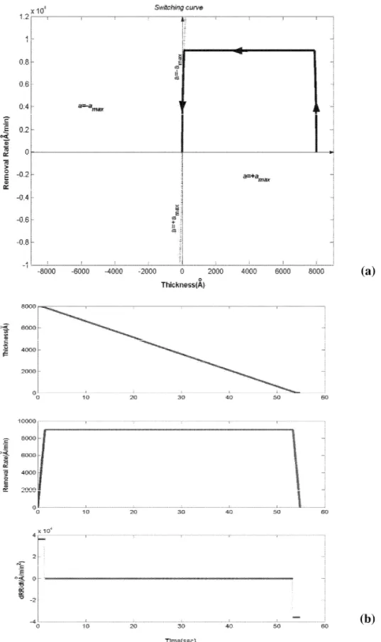
becomes almost vertical when amax reaches 360 000 A / min and, more importantly, this is the performance of most modern CMP stations. With a large slope (e.g., Fig. 4c), the removal rate may become extremely large during the polishing stage. It is obvious that, in practice, some limitation will be imposed on the removal rate.
2
˚ ˚
Consider the case with H 58000 A and RR 50 with a fast acceleration a0 0 max5360 000 A / min ˚
and a top removal rate of RRmax59000 A / min. Following the trajectory in Fig. 4c, initially, the
removal rate is increased with a full acceleration a 5 amax until RR 5 RRmax. Then, the polishing process proceeds with the maximum removal rate and this stage is shown in Fig. 5a as the horizontal crossing. When the path meets the switching curve, the removal rate is decelerated with a 5 2 amax toward the origin. Therefore, this is a three-stage process: acceleration, hold, and deceleration. Fig. 5b shows the changes in thickness, removal rate, and rate change for this example. Obviously, the total polish time will be greater than the unconstrained case. Solving the governing equations, we have:
H0 RRmax
]] ]]
t 5f 1 (23)
2 2
˚ ˚
Fig. 4. Effects of amax on switching curves: (a) amax53600 A / min , (b) amax536000 A / min , and (c) amax5360000
2 ˚
A / min .
]]
If the constraint is not active, i.e., RRmax5 RRsw5 a
œ
maxH , Eq. (23) is reduced to the unconstrained0case, Eq. (22).
3
.3. Handling uncertainty
Fig. 5a also reveals that the deceleration (a 5 2 amax) is activated at a position which is very close to the end point. This could be a potential problem in CMP operation and may result in severe dishing if the copper thickness is not correctly measured or if, more likely, we have within wafer non-uniformity (WIWNU) in the copper thickness (i.e., copper thickness varies across the wafer
2 ˚
Fig. 5. Effect of RRmax on switching curves with amax5360 000 A / min : (a) trajectory, and (b) corresponding operating
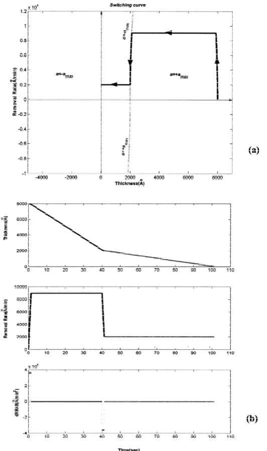
radial position). A question then arises: how can we ensure robust operation under uncertainty? A simple solution is: use the bang-bang control to land the polisher on a higher ground first followed by a careful descent toward the origin (oxide layer). That is, instead of bringing the system to H(t ) 5 0f and RR(t ) 5 0 in minimum time, we set the boundary condition to H(t ) 5 Hf f small and RR(t ) 5 RRf small. Here, Hsmall is a prescribed remaining copper thickness which is associated with WIWNU and a
˚
typical value is around 2000 A. RRsmall is a small removal rate which will give an acceptable dishing
˚
at the over-polish stage and a typical value is close to RR52000 A / min.
With the modified boundary condition, we can solve the optimal control problem using the same procedure as in Section 3.1. Fig. 6 shows the trajectories and switching curves for three different
2 2 2
˚ ˚ ˚
maximum accelerations (amax53600 A / min , 36 000 A / min , and 360 000 A / min ) with H(t )5f
Fig. 6. Endpoint shifts (original: large circle and modified: small circle) to overcome uncertainty and prevent dishing with:
2 2 2
˚ ˚ ˚
˚ ˚
2000 A and RR(t )52000 A / min. Once the landing point is reached, the polisher continues the copperf
˚
removal with the smaller removal rate (RRsmall52000 A / min) until the end point (oxide layer) is
2
˚
detected. With a typical acceleration, amax5360 000 A / min , and a modified landing location, Fig. 7a
gives the trajectory for the entire polishing process and the corresponding state variables and control are also shown in Fig. 7b. The optimal control solution leads to the following polishing strategy: 1. Specify the landing point, Hsmall and RRsmall. Here, Hsmall corresponds to the WIWNU in copper
thickness and RRsmall is related to a small removal rate giving acceptable dishing.
2. Set the removal rate to the maximum removal rate (RR 5 RRmax) until the landing point (H 5 Hsmall) is reached.
3. Switch the removal rate to a smaller value (i.e., RR 5 RRsmall) until the end point (H 5 0) is detected.
Actually, this is the ad hoc procedure practiced by many experienced CMP engineers in the fabs. But, here, the procedure is derived by solving the minimum time problem with typical CMP machine specifications and, more importantly, constraints on achieving the true minimum time are also explored (Eq. (22)). This offers direction for improvement on the next generation CMP station.
4
. Conclusion
In this work, an analogy between the soft landing of a spacecraft and the CMP operation is established. Therefore, the CMP operation can be formulated as a minimum time optimal control problem and the well-known bang-bang control law is derived. Provided with typical CMP machine specifications, constraints preventing the achievable minimum time are also explored and the trajectory is modified accordingly. Uncertainties such as results of thickness measurement and within wafer non-uniformity prevent direct implementation of bang-bang control law and an alternative is proposed by modifying the landing point. Thus, a two-stage CMP operation procedure is devised to ensure robust operation while maintaining a high throughput. This is exactly the ad hoc procedure practiced by many experienced CMP engineers. More importantly, the analytical derivation of the operation procedure offers insights to the design of future CMP stations.
5
. Nomenclature
A state matrix in state space equation a acceleration
amax maximum acceleration
B input matrix in state space equation CMP chemical mechanical polishing H remaining thickness of copper layer H* variational Hamiltonian
J performance index RR removal rate
2
˚ ˚
Fig. 7. Realistic trajectory (a) and corresponding operating variables (b) for RRmax59000 A / min, amax5360 000 A / min ,
˚ ˚
t time
u input of state space equation x state of state space equation WIWNU within wafer non-uniformity Greek symbols
l Lagrange multiplier Subscripts
0 initial state f final state
small a small value for the modified landing point sw switching point
A
cknowledgements
Financial support of the National Science Council of Taiwan is gratefully acknowledged.
R
eferences
[1] A.E. Bryson Jr., Y.C. Ho, Applied Optimal Control, Hemisphere, Washington, D.C, 1975.
[2] C.L. Borst, D.G. Thakurta, W.N. Gill, R.J. Gutmannb, Surface kinetics model for silk chemical mechanical polishing, J. Electrochem. Soc. 149 (2002) G118.
[3] C.Y. Chen, C.C. Yu, S.H. Shen, M. Ho, Operational aspects of chemical mechanical polishing: polish pad profile optimization, J. Electrochem. Soc. 147 (2000) 3922.
[4] D.Z. Chen, B.S. Lee, Pattern planarization model of chemical mechanical polishing, J. Electrochem. Soc. 146 (1999) 744–748.
[5] T.F. Edgar, S.W. Butler, W.J. Campbell, C. Pfeiffer, C. Bode, S.B. Hwang, K.S. Balakrishnan, J. Hahn, Automatic control of microelectronics manufacturing: practices, challenges and possibilities, Automatica 36 (2000) 1567. [6] F.B. Kaufman, D.B. Thompson, R.E. Broadie, M.A. Jaso, W.L. Guthrie, D.J. Pearson, M.B. Small,
Chemical-mechanical polishing for fabricating patterned W metal features as chip interconnects, J. Electrochem. Soc. 138 (1991) 3460–3465.
[7] Y.C. Kao, C.C. Yu, S.H. Shen, Robust operation of copper chemical mechanical polishing, Microelectron. Eng. 65 (2002) 61–75.
[8] D.E. Kirk, Optimal Control Theory: An Introduction, Prentice-Hall, NJ, 1970.
[9] S. Prasad, W. Loh, A. Kapoor, E. Chang, B. Stein, D. Boning, J. Chung, Statistical metrology for characterizing CMP processes, Microelectron. Eng. 33 (1997) 231.
[10] S.R. Runnels, L.M. Eyman, Tribology analysis of chemical mechanical polishing, J. Electrochem. Soc. 141 (1994) 1689–1701.
[11] A.P. Sage, C.C. White III, Optimum Systems Control, 2nd Edition, Prentice-Hall, NJ, 1977.
[12] W.T. Tseng, Y.L. Wang, Re-examination of pressure and speed dependence of removal rate during chemical– mechanical polishing process, J. Electrochem. Soc. 144 (1997) L15.
[13] C.H. Yao, D.L. Feke, K.M. Robinson, S. Meikleb, The influence of feature-scale surface geometry on CMP processes, J. Electrochem. Soc. 147 (2000) 3094.