This content has been downloaded from IOPscience. Please scroll down to see the full text.
Download details:
IP Address: 140.113.38.11
This content was downloaded on 26/04/2014 at 04:46
Please note that terms and conditions apply.
Calcium alginate microcapsule generation on a microfluidic system fabricated using the
optical disk process
View the table of contents for this issue, or go to the journal homepage for more 2007 J. Micromech. Microeng. 17 1428
(http://iopscience.iop.org/0960-1317/17/8/003)
J. Micromech. Microeng. 17 (2007) 1428–1434 doi:10.1088/0960-1317/17/8/003
Calcium alginate microcapsule generation
on a microfluidic system fabricated using
the optical disk process
Keng-Shiang Huang
1, Ming-Kai Liu
1, Chun-Han Wu
2,
Yu-Tang Yen
1and Yu-Cheng Lin
1,31Department of Engineering Science, National Cheng Kung University, Taiwan, Republic of China
2Department of Mechanical Engineering, National Chiao Tung University, Taiwan, Republic of China
3Center for Micro/Nano Technology, National Cheng Kung University, Taiwan, Republic of China
E-mail:[email protected]
Received 11 January 2007, in final form 25 May 2007 Published 21 June 2007
Online atstacks.iop.org/JMM/17/1428
Abstract
This paper describes the generation of monodisperse calcium alginate (Ca-alginate) microcapsules on a microfluidic platform using the commercial optical disk process. Our strategy is based on combining the rapid injection molding process for a cross-junction microchannel with the sheath focusing effect to form uniform water-in-oil (w/o) emulsions. These emulsions, consisting of 1.5% (w/v) sodium alginate (Na-alginate), are then dripped into a solution containing 20% (w/v) calcium chloride (CaCl2)
creating Ca-alginate microparticles in an efficient manner. This paper demonstrates that the size of Ca-alginate microparticles can be controlled from 20 µm to 50 µm in diameter with a variation of less than 10%, simply by altering the relative sheath/sample flow rate ratio. Experimental data show that for a given fixed dispersed phase flow (sample flow), the emulsion size decreases as the average flow rate of the continuous phase flow (sheath flow) increases. The proposed microfluidic platform is capable of generating relatively uniform emulsions and has the advantages of active control of the emulsion diameter, a simple and low cost process and a high throughput. (Some figures in this article are in colour only in the electronic version)
1. Introduction
Polymer-based technologies (CO2-laser, hot-embossing, mold
injection, lithography electroforming micro molding (LIGA), LIGA-like and others) have been widely applied to fabricate biomedical devices that meet the requirements of low cost, flexible process and have the capability of being mass-produced [1–4]. However, high cost and/or a long cycle time limits their application [5–8]. For example, when the conventional optical disk technique (mold injection) is used for fabricating the microfluidic substrate, the mold insert induces an opposite electroform pattern on the backside. Generally speaking, this backside pattern of the mold insert damages
the mold. Therefore, the mold insert must be polished prior to being integrated with the mold. However, this backside polishing process must be well controlled so as to prevent overstress, since overstressing will warp the mold insert and causes a loss of vacuum. Recently, we proposed a new method for a mold insert, and it overcomes the problems above [9]. We also use it for the fabrication of microfluidic substrates, putting great emphasis on the parameters of the fabrication process and the material characteristics. In the present study, we focus on the further application of this new technique for mass production of microfluidic disks. We also design a new pattern for the microchannel cross-junction, and apply it in the generation of calcium alginate (Ca-alginate) microcapsules.
Calcium alginate microcapsule generation on a microfluidic system Photo resist Metal plate Mask UV exposure Developing Stamper Electroforming Substrate Stamper
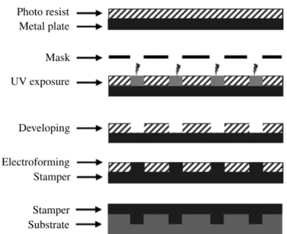
Figure 1. The optical disk fabrication process for (a) microfluidic substrates and (b) optical disk substrates.
Ca-alginate is currently receiving a great deal of attention for medical applications and for the controlled release of drugs [10]. To date, the production of Ca-alginate microcapsules has been accomplished mainly by using external gelation (dripping method). For example, sodium alginate (Na-alginate) is extruded dropwise through a needle into a solution of divalent cations, which induces crosslinking of the guluronic residues of the alginate polymer [11–14]. The alternative techniques are as follows: (i) atomization (spray-drying) [15, 16], (ii) coacervation [17], (iii) emulsification (internal/external gelation) [18–21] and other methods. However, all of these techniques have well-known drawbacks such as unstable yield, tedious procedures and non-uniform particle sizes with a wide size distribution. Consequentially, it has become imperative for the pharmaceutical industry to develop a reproducible method for generating Ca-alginate microcapsules in a controlled manner, with a uniform particle size and a narrow size distribution.
Microfluidic emulsification has been used for the fabrication of monodisperse water-in-oil (w/o), oil-in-water (o/w) emulsions and for bubbles, and then for creating monodisperse polymeric microparticles by curing emulsion droplets containing a monomer solution [22–29]. Recently, we proposed a novel microfluidic device that utilized a polymethylmethacrylate (PMMA) microfluidic chip to produce 50–2000 µm Ca-alginate microcapsules with a variation within 5% [30]. However, using a CO2-laser machine
or making a microfluidic structure on a PMMA sheet is not suitable for mass production. Also, the smallest width of the microfluidic channel is limited to 200 µm. In addition, this method is not sufficiently precise, nor is it suitable for the prototype since it will damage the surface of the substrate of the microfluidic channel.
The fabrication process for the microfluidic chip in this study is shown in figure1. The industrial high-speed injection machine, Sumitomo SD-35E, and the Seiko Giken F-type optical disk mold (the use of which was provided to us by RITEK Corporation, Hsinchu, Taiwan, ROC) were employed to fabricate the microfluidic chip. Except for the fabrication of the mold insert, the injection molding process of the microfluidic chip is the same as the conventional optical disk process [3,9]. Therefore, the fabrication process proposed in
this study is a time-saving, low-cost, flexible process. It has high-resolution, multi-functional structures on a uni-substrate, and it is suitable for mass production. In addition, we applied the proposed disk microfluidic chip for the generation of 20–50 µm monodisperse Ca-alginate microcapsules. The inference between the emulsion size and flow rate, and the encapsulation of immunoglobulin (IgG) and gold nanoparticles (AuNPs) were also studied.
2. Materials and methods
2.1. Materials
The material of the microfluidic substrates in this experiment is optical grade polycarbonate (PC, AD5503, Teijin Corporation, Japan). The glass transition temperature is approximately 145◦C. The cylinder temperature is controlled from 320◦C to 380◦C, and the temperature of the stationary-side mold is controlled from 100◦C to 120 ◦C. The commercial sample of low-viscosity Na-alginate (viscosity 250 mPa s in 1.5% (w/v) solution at 25 ◦C; brown algae) was purchased from Sigma Chemical Co. (MO, USA). Sunflower seed oil (viscosity 55 mPa s) was purchased from Uni-President Enterprises Corp., Taiwan. Human serum IgG was purchased from Sigma-Aldrich Co. All other chemicals (calcium chloride purchased from Panreac Quimica SA) were of analytical grade and were used without further purification.
2.2. Preparation of gold nanoparticles (AuNPs)
In a 250 mL round-bottom flask equipped with a condenser, 100 mL of 1 mM HAuCl4was brought to rolling boil while
being stirred vigorously. Then 10 mL of 38.8 mM sodium citrate was quickly added to the vortex of the solution. The mixture was then heated to 55◦C in an oil bath with magnetic stirring until a deep-wine-red color was obtained, indicating the formation of a AuNPs suspension. The heating mantle was then removed, and stirring was continued for an additional 15 min. After the solution reached room temperature, it was filtered through a 0.8 µm Gellman membrane filter. The resulting solution of colloidal particles was characterized by an absorption maximum at 520 nm. The prepared AuNPs had a narrow distribution of particle size with a mean diameter of about 5± 0.8 nm (100 particles sampled).
2.3. Microfluidic substrate molding [9]
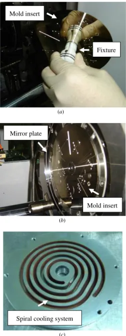
In this study, the injection molding was conducted on a high-speed injection machine (Sumitomo SD-35E), and the Seiko Giken F-type optical disk mold was adopted. There are two steps to integrate the mold insert with the mold. First, the mold insert is hung on the fixture (figure2(a)). Second, the vacuum system of the mold is used to keep the mold insert on the mirror plate (figure 2(b)). The details of the optical disk process are described as follows (figure1). First, a piece of nickel (Ni) plate, 300 µm thick, was electroformed, and then the photoresist (PR) was coated 20–200 nm thick on its surface. Next, the PR on the Ni was exposed and developed. Finally, the Ni plate was electroformed into a 50 µm thick plate again, and then the mold insert (stamper) was finished. With the appropriate injection parameter adjusted, the plastic optical disk substrates could be fabricated.
(a) (b) (c) Mold insert Fixture Mirror plate Mold insert
Spiral cooling system
Figure 2. Photo images of (a) microfluidic mold insert hung on the fixture, (b) mold insert hung on the mold and (c) the spiral cooling system behind the mirror plate.
2.4. Principle of emulsification and gelation
Generating a narrow size distribution of self-assembling emulsions is based on the focusing force in the cross-junction channel (figure 3(a)). The mechanism of the microfluidic cross-junction provides a finer control of the emulsion sizes by varying the ratio between the dispersed and the continuous phase flow rates [31]. Based on the outstanding performance of the microfluidic platform, we utilized it in this work for pharmaceutics (e.g. Ca-alginate microcapsule generation). We report the use of microfluidics in our attempt to obtain control over the spontaneous self-assembly of water-in-oil (w/o) emulsions from a solution of dissolved Na-alginate. These semi-products (emulsions) were then dripped into a solution containing calcium (II) ions, resulting in the instantaneous formation of Ca-alginate microcapsules. The
2 Na-alginate + CaCl2 Ca-alginate + 2 NaCl
Oil Oil Aqueous buffer Syringe pumps Na-alginate emulsions Oil Ca2+ buffer Tube Ca-alginate microcapsules (a) (b) (c)
Figure 3. Illustrations of the system mechanism: (a) a schematic drawing of a Na-alginate emulsion generator in a cross-junction microchannel, (b) the mechanism of Na-alginate polymerization: the chemical reaction in the reservoir consists of the sodium ions of the alginate being substituted by calcium ions, indicating the formation of Ca-alginate microcapsules and (c) a reservoir. mechanism of the synthesis of Ca-alginate microcapsules consisted of the calcium (II) ions released by CaCl2undergoing
crosslinking with Na-alginate emulsions and produced Ca-alginate microcapsules (external gelation, as shown in figure3(b)) [20].
2.5. Experimental procedure
Figure4shows an overview of the experimental setup. The procedure is as follows. First, the fluids of the center and side inlet channels were connected to 3 mL 1.5% (w/v) Na-alginate solution (dispersed phase) and 3 mL sunflower seed oil (continuous phase), respectively. The material to be encapsulated is mixed with an alginate solution. Second, the fluids are then injected into the microfluidic platform by syringe pumps (Kdscientific KDS230) programmed by a PC. In this work, we hydrodynamically focused a stream of Na-alginate solution at a cross-junction microchannel by means of two oil streams, enabling the construction of w/o Na-alginate emulsions in the microchannel. Finally, the Na-alginate emulsions then underwent gelation and were dripped into a calcium (II) ion solution to form Ca-alginate microcapsules.
2.6. Emulsion size measurement
An inverted fluorescent microscope was used to observe the experimental results. The image and detection system consisted of an optical microscope (BX60, Olympus, Japan) and a digital camera (DP70, Olympus, Japan). The diameter of each emulsion was measured and averaged. A total of 50 emulsions were measured to provide an average size.
3. Results and discussions
3.1. Injection molding system
This paper proposed an optical disk process for the mass production of a microfluidic substrate, as shown in figure1.
Calcium alginate microcapsule generation on a microfluidic system Reservoir Syringe pump Oil inlet Syringe pump Sample inlet CCD camera Outlet Microfluidic substrate
Figure 4. Setup of the emulsion-generation system for Ca-alginate microcapsule generation and the observation platform with a CCD camera.
The Ni plate was used in the process to prevent the backside pattern from being formed on the mold insert. Therefore, the mold insert created by our proposed method did not damage the mirror plate of the mold. In addition, in order to reduce the cycle time, the molding system was water cooled using a spiral cooling system behind the mirror plate (figure2(c)). In addition, our molding system used a mold insert holder and a vacuum system to combine the mold insert and the mold, which substantially reduced the time required to change the mold insert.
3.2. The microfluidic platform
The platform consists of four layers from top to bottom (an expanded view is shown in figure 5(a)): the cover layer (containing one outlet port and three inlet ports), the meso-layer (to prevent the fluids from leaking out), the microfluidic substrate (the cross-junction channel, depth/width: 50 µm/ 50 µm) and the bottom layer (the disk structure, 110 mm in diameter is designed in a modular fashion for placing on an inverted fluorescent microscope), respectively. The cover and bottom layers are both laid out on conventional PMMA using a CO2-laser machine (LaserPro Venus, GCC, Taiwan). The
meso-layer was fabricated with polydimethylsiloxane (PDMS) by PMMA molding. Finally, these four layers are fastened together with screws (see figure5(b)). The cross-junction we used in this study has three inlet ports, one outlet port, one cross channel (50 µm wide) and an observation area, as shown in figure5(b). The observation area (400 µm wide, much wider than the cross channel) is designed to slow down the flow and enhance the observation.
3.3. Formation of Na-alginate emulsions and Ca-alginate microcapsules
In the experiments, the flow rates of the dispersed and the continuous phases were set to 1.0 µL min−1. We found that the dispersed phase flow was compressed by a shear force to an arrow shape (see figure 6(b), the outlet of the cross-junction channel) and then separated into emulsions of about 50 µm in diameter. In addition, the diameter distribution of the emulsions formed was quite uniform (50 ± 5 µm), and the gap between each emulsion was stable (75± 5 µm). At the cross junction, the water stream (dispersed phase) sent
(a) (b) Teflon tube Silicon tube PDMS Microfluidic substrate PMMA (Top) PMMA (Bottom) Screw hole
1
3
2
6
7
4 5
Figure 5. (a) Expanded view and (b) photo of the microfluidic platform: 1–3, inlet ports; 4, cross-channel; 5, observation area; 6, outlet port; and 7, screws.
through the middle channel was sheared and cut by the oil stream (continuous phase) sent through the outer channel. The competition between interfacial tension and imposed pressure gradient (syringe pump) at the oil/water interface resulted in droplets of a finite diameter [32]. In addition, the arrow shape of the droplets was observed in the experiments. Generally, in a pressure-driven droplet flow, the front and rear droplets have different curvatures (the differential capillary 1431
Qw Qo Qo (a) (b) (e) (g) (h) ( f ) (c) (d) Flow direction 50 µm
Figure 6. The w/o Na-alginate emulsion generation: (a) chart of flow directions, (b) to (h) show the emulsion generation at a fixed oil flow rate (Qo) and the water flow rate (Qw) is reduced from (b) to (h).
pressures account for an axial pressure drop). According to the Bretherton problem [33], the ends of the emulsion forming two hemispherical caps filling the cross-section of the tube involve infinite viscous stresses at the wall. The only physical forces maintaining the shape of the ends against these stresses are those due to the uniform pressure within the emulsion, surface tension and gravity. The flow rates of the dispersed and continuous phase were adjusted to control the degree of hydrodynamic focusing and the width of the center stream, resulting in the generation of size-controlled Na-alginate emulsions. Therefore, we concluded that hydrodynamic focusing can perform the emulsification in a size-controlled manner. In order to extract these emulsions for advanced applications, we solidified the Na-alginate emulsions by gelation.
The continuous phase can prevent these semi-products from fusing together, and transport the semi-products (Na-alginate emulsions) to the 20% (w/v) calcium chloride solution through a Teflon tube. Their higher density compared to that of the oil enables them to precipitate spontaneously at the bottom of the oil. Therefore, Na-alginate emulsions react with the calcium (II) ion at the interface between the oil and the aqueous phase. After the water-soluble Na-alginate emulsions have undergone crosslinking (figure3(b)), they gel into solid capsules upon contact with the calcium (II) ion by means of external gelation, resulting in water-insoluble Ca-alginate microcapsules.
3.4. Influence of flow rate and viscosity
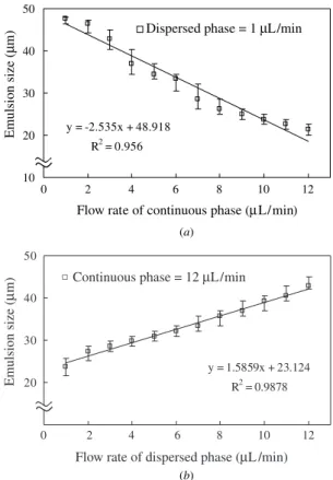
Figure 6 shows the relationship between the average flow rate of the phases and the emulsion size (diameter); it is evident that the size and the gap of the emulsions generated in the cross-junction are controllable and reproducible by using the microfluidic platform. For any given 1.0 µL min−1of the dispersed phase flow rate, the emulsion size decreases as the average flow rate of the continuous phase increases. The
(a) (b) y = -2.535x + 48.918 R2 = 0.956 10 20 30 40 50 0 2 4 6 8 10 12
Dispersed phase = 1 µL/min
Emulsion size (
µ
m)
Flow rate of continuous phase (µL/min)
y = 1.5859x + 23.124 R2 = 0.9878 20 30 40 0 2 4 6 8 10 12 50
Continuous phase = 12 µL/min
Flow rate of dispersed phase (µL/min)
Emulsion size (
µ
m)
Figure 7. Evaluation of the emulsion size by varying (a) the continuous phase and (b) the dispersed phase flow rate. The emulsion size decreases the higher the ratio of the dispersed to the continuous phase flow rate.
same tendency was observed in the other dispersed phase flow. Figure7(a) shows the examples of the above and the linear regression calculation of the emulsion size. We found that increasing continuous phase flow rates (at a fixed dispersed
Calcium alginate microcapsule generation on a microfluidic system
(a)
(b)
Figure 8. The UV–VIS spectrum of (a) IgG, Na-alginate solution and IgG-loaded Ca-alginate microcapsules and (b) 13 nm AuNPs, Na-alginate and AuNPs-loaded Ca-alginate microcapsules. phase flow rate) can obtain smaller emulsions. Moreover, for any given 12.0 µL min−1of continuous phase flow rate, the emulsion size increased as the average flow rate of the dispersed phase increased. The same tendency was observed in the other continuous phase flow. Figure7(b) shows that increasing the dispersed phase flow rates (at a fixed continuous phase flow rate) results in larger emulsions and a linear regression trend. Furthermore, using the sheath focusing effect of the cross-junction to study the flow-rate dependence of the droplet size is a very well-studied phenomenon [26–29]. Our results are similar to the previous studied [26–29].
In addition, the influence of the continuous phase viscosity on the emulsification was studied. We found that the average emulsion size also depends on the different viscosities in the continuous phases. These results are similar to the studies of Guillot and Colin [34] and Xu et al [35]. It was also found that the emulsion size decreases with the increase in the continuous phase rate and its viscosity, while at the same time being independent of the surface tension. Moreover, Babak et al [36], Zhang et al [37] and Widom [38] investigated the fact that surfactants reduce the interface tension between oil phase and water phase, which enables them to be mixed and emulsify. Therefore, a relatively low surface tension of the
emulsions indicates a better emulsification effect and a higher stability.
3.5. Encapsulation and analysis
Simply by mixing the water-soluble drugs with the Na-alginate solution well, an excellent level of entrapment efficiency can be observed. We first examined the encapsulation of IgG and AuNPs to verify the applicability of this microfluidic technique. Then a well-mixed mixture followed the general experimental procedure (as mentioned above) to obtain IgG-loaded and AuNPs-IgG-loaded Ca-alginate microcapsules. The entrapment efficiency of IgG and AuNPs was determined by a UV spectrophotometer (HP 8453, Agilent, Germany).
We found that neat 1.5% (w/v) Na-alginates were not absorbent in UV–VIS, but after being mixed respectively with 1.0 mg/mL IgG (1.0 mg/mL IgG/1.5% (w/v) Na-alginate in 1:1) and 0.1 nM 13 nm AuNPs (0.1 nM 13 nm AuNPs/1.5% (w/v) Na-alginate in 1:10) the absorbance with peaks of around 275 and 520 nm were observed. Furthermore, the absorption spectra of IgG-loaded and AuNPs-loaded Ca-alginate microcapsules showed the broad peaks of around 275 nm and 520 nm, as shown in figures 8(a) and (b), respectively, indicating that IgG and AuNPs were entrapped in the Ca-alginate microcapsules. It is worth noting that the absorption intensity results before and after gelation were similar. We presume that there is virtually no loss during the encapsulation process.
4. Conclusion
This study demonstrates microcapsule generation using a microfluidic device fabricated using an injection molding process similar to that employed in making optical disks. The industrial high-speed injection machine and the conventional optical disk mold were employed to fabricate the microfluidic disk. Therefore, the fabrication process proposed in this study is a time-saving, low-cost, flexible process. It has high-resolution, multi-functional structures on a uni-substrate, and it is suitable for mass production. In addition, this study demonstrates a microfluidic platform that utilizes a cross-junction microchannel enabling it to produce 20–50 µm Ca-alginate microcapsules with a narrow size distribution (<10%). We found that the continuous phase flow can pose a focusing/shear force on the dispersed phase flow in the microchannel. This adds to its use as a dynamic control of the emulsion size. Our platform is very attractive from a practical point of view, since it easily emulsifies and yields extremely uniform emulsions with a very high loading capacity. The approach of manipulating Ca-alginate microcapsules has many potential pharmaceutical applications.
Acknowledgments
The authors would like to thank the Center for Micro/Nano Technology, National Cheng Kung University, Tainan, and RITEK Corporation, Hsinchu Taiwan, ROC for access to their equipment and for their technical support. Funding from the Ministry of Education and the National Science Council of Taiwan, ROC under contract numbers NSC 95-2323-B-006-005 and NSC 95-2323-B-006-006 is gratefully acknowledged. 1433
References
[1] Madou M J, Lee L J, Koelling K W, Dauner S, Koh C G, Juang Y J, Lu Y and Lu L 2001 Design and fabrication of CD-like microfluidic platforms for diagnostics:
polymer-based microfabrication Biomed. Microdevices 3 339–51
[2] Madou M J, Lee L J, Dauner S, Lai S and Shih C H 2001 Design and fabrication of CD-like microfluidic platforms for diagnostics: microfluidic functions Biomed.
Microdevices3 245–54
[3] Bifano T G, Fawcett H E and Bierden P A 1997 Precision manufacture of optical disc master stampers Precis.
Eng.20 53–62
[4] Lee L J 2003 BioMEMS and micro-/nano-processing of polymers—an overview J. Chin. Inst. Chem. Eng. 34 25–46 [5] Klank H, Kutter J P and Geschke O 2002 CO2-laser
micromachining and back-end processing for rapid production of PMMA-base microfluidic systems
Lab Chip2 242–6
[6] Despa M S, Kelly K W and Collier J R 1999 Injection molding of polymeric LIGA HARMs Microsyst. Technol.6 60–6 [7] Alonso-Amigo G 2000 Polymer microfabrication for
microreactors and microfluidics J. Assoc. Lab. Autom. 5 96–101
[8] Chien R D 2006 Micromolding of biochip devices designed with microchannels Sensors Actuators A128 238–47 [9] Wu C H, Chen C H, Fan K W, Hsu W S and Lin Y C 2007
Design and fabrication of polymer microfluidic substrates using the optical disc process Sensors Actuators A at press (DOI: 10.1016/j.sna.2006.11.038)
[10] Morgan S M, Al-Shamkhani A, Callant D, Schacht E, Woodley J F and Duncan R 1995 Alginates as drug carriers-covalent attachment of alginates to therapeutic agents containing primary amine groups Int. J.
Pharm.122 121–8
[11] Gombotz W R and Wee S F 1998 Protein release from alginate matrices Adv. Drug Deliv. Rev.31 267–85
[12] Iskakov R M, Kikuchi A and Okano T 2002
Time-programmed pulsatile release of dextran from calcium alginate gel beads coated with carboxy-n-propylacrylamide copolymers J. Control. Release80 57–68
[13] Shamkhani A A and Duncan R 1995 Synthesis, controlled release properties and antitumour activity of
alginate-cis-aconityldaunomycin conjugates Int. J.
Pharm.122 107–19
[14] Patrick S S 1999 Treatment of type I diabetes using encapsulated islets Adv. Drug Deliv. Rev. 35 259–70 [15] Coppi G, Iannuccelli V, Bernabei M T and Cameroni R 2002
Alginate microparticles for enzyme peroral administration
Int. J. Pharm.242 263–6
[16] Hall R D et al 1996 A high efficiency technique for the generation of transgenic sugar beets from stomatal guard cells Nature Biotechnol. 14 1133–8
[17] Chen S C, Wu Y C, Mi F L, Lin Y H, Yu L C and Sung H W 2004 A novel pH-sensitive hydrogel composed of N,
O-carboxymethyl chitosan and alginate cross-linked by
genipin for protein drug delivery J. Control. Release 96 285–300
[18] Liu X D, Bao D C, Xue W M, Xiong Y, Yu W T, Yu X J, Ma X J and Yuan Q 2003 Preparation of uniform calcium alginate gel beads by membrane emulsification coupled with internal gelation J. Appl. Polym. Sci. 87 848–52 [19] You J O, Park S B, Park H Y, Haam S, Chung C H and
Kim W S 2001 Preparation of regular sized Ca-alginate microspheres using membrane emulsification method
J. Microencapsul. 18 521–32
[20] Chan L W, Lee H Y and Heng P W S 2002 Production of alginate microspheres by internal gelation using an emulsification method Int. J. Pharm. 242 259–62 [21] Ribeiro A J, Silva C, Ferreira D and Veiga F 2005
Chitosan-reinforced alginate microspheres obtained through the emulsification/internal gelation technique Eur. J.
Pharm. Sci. 25 31–40
[22] Link D R, Anna S L, Weitz D A and Stone H A 2004 Geometrically mediated breakup of drops in microfluidic devices Phys. Rev. Lett.92 054503
[23] Willaime H, Barbier V, Kloul L, Maine S and Tabeling P 2006 Arnold tongues in a microfluidic drop emitter Phys. Rev.
Lett.96 054501
[24] Nisisako T, Okushima S and Torii T 2005 Controlled formulation of monodisperse double emulsions in a multiple-phase microfluidic system Soft Matter1 23–7 [25] Cristini V and Tan Y C 2004 Theory and numerical simulation
of droplet dynamics in complex flows—a review Lab Chip 4 257–64
[26] Tan Y C, Cristini V and Lee A P 2006 Monodispersed microfluidic droplet generation by shear focusing microfluidic device Sensors Actuators B114 350–6 [27] Yobas L, Martens S, Ong W L and Ranganathan N 2006
High-performance flow-focusing geometry for spontaneous generation of monodispersed droplets Lab Chip6 1073–9 [28] Ward T, Faivre M, Abkarian M and Stone H A 2005
Microfluidic flow focusing: drop size and scaling in pressure versus flow-rate-driven pumping
Electrophoresis26 3716–24
[29] Xu S, Nie Z, Seo M, Lewis P, Kumacheva E, Stone H A, Garstecki P, Weibel D B, Gitlin I and Whitesides G M 2005 Generation of monodisperse particles by using
microfluidics: control over size, shape, and composition
Angew. Chem. Int. Ed.21 724–8
Xu S, Nie Z, Seo M, Lewis P, Kumacheva E, Stone H A, Garstecki P, Weibel D B, Gitlin I and Whitesides G M 2005
Angew. Chem. Int. Ed.22 3799
[30] Huang K S, Lai T H and Lin Y C 2006 Manipulating the generation of Ca-alginate microspheres using microfluidic channels as a carrier of gold nanoparticles Lab Chip 6 1–5 [31] Sugiura S, Oda T, Izumida Y, Aoyagi Y, Satake M, Ochiai A,
Ohkohchi N and Nakajima M 2005 Size control of calcium alginate beads containing living cells using micro-nozzle array Biomaterials26 3327–31
[32] Collins J, Tan Y C and Lee A P 2003 Optimization of shear driven droplet generation in a microfluidic device ASME
Int. Mechanical Engineering Congress and R&D Expo 2003 (Washington, DC)
[33] Bretherton F P 1961 The motion of long bubbles in tubes J.
Fluid Mech.10 166–88
[34] Guillot P and Colin A 2005 Stability of parallel flows in a microchannel after a T junction Phys. Rev. E
72 066301
[35] Xu J H, Li S W, Chen G G and Luo G S 2006 Formation of monodisperse microbubbles in a microfluidic device AIChE
J. 52 2254–59
[36] Babak V G, Skotnikova E A, Lukina I G, Pelletier S, Hubert P and Dellacherie E 2000 Hydrophobically associating alginate derivatives: surface tension properties of their mixed aqueous solutions with oppositely charged surfactants J. Colloid Interface Sci.225 505–10
[37] Zhang F J, Cheng G X, Gao Z and Li C P 2006 Preparation of porous calcium alginate membranes/microspheres via an emulsion templating method Macromol. Mater. Eng. 291 485–92
[38] Widom B 1984 A model microemulsion J. Chem. Phys. 81 1030–47