A polarization-independent liquid crystal phase modulation using
polymer-network liquid crystal with orthogonal alignment layers
Ming-Syuan Chen, Wei-Chih Lin, Yu-Shih Tsou and Yi-Hsin Lin
*Department of Photonics, National Chiao Tung Unversity, 1001 Ta Hsueh Rd., Hsinchu 30010,
Taiwan
*
Corresponding author: [email protected]
ABSTRACT
A polarization-independent liquid crystal (LC) phase modulation using polymer-network liquid crystals with orthogonal alignments layers (T-PNLC) is demonstrated. T-PNLC consists of three layers. LC directors in the two layers near glass substrates are orthogonal to each other. In the middle layer, LC directors are perpendicular to the glass substrate. The advantages of such T-PNLC include polarizer-free, larger phase shift (~0.4π rad) than the residual phase type (<0.05π rad), and low operating voltage (< 30Vrms). It does not require bias voltage for avoiding scattering because the refractive index of liquid crystals matches that of polymers. The phase shift of T-PNLC is affected by the cell gap and the curing voltages. The potential applications are laser beam steering, spatial light modulators and electrically tunable micro-lens arrays.
Keywords: Liquid-crystal devices; Phase modulators; Polarization independent phase modulators.
1. INTRODUCTION
Electrically tunable liquid crystal (LC) phase-only modulations are important in many applications, such as laser beam steering1, tunable focus lenses2-6, electrically tunable gratings and prisms7, and spatial light modulators8. To obtain high optical efficiency, four main types of polarization independent LC phase modulator have been demonstrated.9-17 They are the residual phase type9-12, the double-layered type9,13-14, the mixed type which is the combination of the residual phase type and the double-layered type15, and the type which is based on the optical isotropy induced by Kerr effect of BP-LC16. In those four types of LC phase modulations, the double-layered type has the largest phase shift.
double-layered structure was proposed17. However, it requires the bias voltage (>5.5Vrms) to achieve polarization independent and the unavoidable heating effect of dual-frequency liquid crystals hinders the practical applications.It is very important to realize an electrically tunable liquid crystal phase-only modulation with polarizer free, low driving voltages, a large phase shift, easy fabrication process, and no bias voltages.
In this paper, a polarization-independent liquid crystal phase modulation using polymer-network liquid crystal with orthogonal alignment layers (T-PNLC) is demonstrated. We applied a vertical electric field during the polymerization process. After polymerization process, the orientations of LC directors are confined to the rubbing directions in the regions near the alignment layers. In the region far from the alignment layers or the bulk region, LC directors are perpendicular to the glass substrate and contribute no phase shift. As a result, T-PNLC is polarization independent. We do not need to apply any bias voltages. Therefore, the operating voltage is low (< 30Vrms) and phase shift is larger (~0.4π rad). The phase shift of T-PNLC is affected by the cell gap and the curing voltages. The potential applications are laser beam steering, spatial light modulators and electrically tunable micro-lens arrays.
2. OPERATING MECHANISM
The structure and operating principles of the polarization independent LC phase modulation using T-PNLC is illustrated in Figure 1(a) and 1(b).The structure consists of two ITO glass substrates, two alignment layers, LC directors located in the domains surrounding by polymer networks which are perpendicular to the glass substrates. The polymer networks are made of polymer grains. The rubbing directions of two alignment layers are orthogonal to each other (i.e. x- and y-directions). As a result, without applied voltage, LC directors in the region near the alignment layers are also orthogonal to each other. The effective thickness of two LC layers near two alignment layers is d1. The effective thickness of the bulk region of T-PNLC is d2. Therefore, (2d1+d2) equals to the cell gap (d). The LC directors in the bulk region are parallel to z-direction, as shown in Figure 1(a).
Glass substrate ITO Alignment layer LC Polymer network z x
(a)
Glass substrate V(b)
Glass substrate Glass substrate
Glass substrate ITO Alignment layer LC Polymer network z x
(a)
Glass substrate V(b)
Glass substrate Glass substrate
Figure 1 : Structure and operating principles of T-PNLC. (a) Without applied voltage, LC directors near two alignment layers are orthogonal to each other, and LC directors in the bulk region are parallel to z-direction. (b) As applied voltage increases, LC directors near two alignment layers are reoriented by the electric field and then perpendicular to the alignment layers.18
decomposed into two linear eigen-modes, x and y linearly polarized lights. The electric field of the incident light can be written as15
( )
( )
(
, ˆ , ˆ)
] ) , ( [ ~ ) , ( j 0x 0y j j inout r t a r t A r t x A r t y Er r Σ r × r × + r × , (1)whereA0x
( )
rr,t andA0y( )
rr are two complex numbers that are functions of the position ,t( )
rr and the time( )
t . The coefficient aj( )
rr is a complex weighting factor for the jth component, and ,t(
A0x( )
rr,t ×xˆ+A0y( )
rr,t ×yˆ)
represents thepolarization state of the jth component. The total accumulated phase (δ) of the x and y components of the polarization of the incident light is attributed to two parts. One is the two regions near the alignments layers. The phase modulation is similar to the double-layered type of phase modulations. As a result, the phase of the two eigen-polarizations is
) ) ( )
(
(k×n1
θ
×d1+k×noθ
×d1 , where k is a wave number, n1(θ) is the effective refractive index depending on the tilt angleθ, and no is the ordinary refractive index of LC materials. The other part is the bulk region of T-PNLC. The LC director in the bulk region is always parallel to z-direction. Thus, the accumulated phase is a constant:k×no×d2. Thetotal accumulated phase can be expressed
1 2 1 1
(
)
d
k
n
d
k
n
d
n
k
×
×
+
×
o×
+
×
o×
=
θ
δ
. (2) After incident light passes through a T-PNLC cell, the electric filed of the output light is)
,
( t
r
E
outputr
r
}
]
ˆ
)
,
(
ˆ
)
,
(
[
)
,
(
{
0 ) ) ( ( 0 ) ) ( ( 1 1 2 1 1 2 1 1 j y d n k d n k d n k i x d n k d n k d n k i j ja
r
t
e
A
r
t
x
e
A
r
t
y
o o o o×
×
+
×
×
×
Σ
=
r
× × θ × + × × + ×r
× × × + × × + × θ ×r
. (3)We can arrange Eq. (3), and it can be represented as
)
,
(
)
,
(
int ) ) ( ( 1 1 2 1E
r
t
e
t
r
E
put d n k d n k d n k i output o or
r
r
r
×
=
× × θ × + × × + × . (4)In Eq. (4), the polarization state is the same between output and input light. The only difference is the phase shift. There fore, T-PNLC is polarization independent. At V=0, we assume LC directors near the alignment layers have a pretilt angle We can consider a randomly polarized light incident to T-PNLC at a normal angle. The unpolarized light can be
two alignment layers, as shown in Figure 1(b). The difference of the phase shift (Δδ) between high voltage and 0 is ] ) ) ( [(n1 n d1 k× p − o × = Δδ θ . (5) Therefore, by operating different applied voltage to T-PNLC, we can realize a polarization independent phase modulation.
3. EXPERIMENTAL RESULTS AND DISCUSSION
3.1 T-PNLC under different curing voltages
The detailed fabrication process of T-PNLC was proposed18. For testing the T-PNLC with different curing voltages, we prepared the samples with an identical cell gap of 5.6μm and applied different curing voltages. To understand the orientation of LC directors of the sample after photo-polymerization, we observed the samples under two crossed polarizers. Figure 2(a) and Figure 2(b) show the images of the samples with a curing voltage (Vc) of 0 Vrms and 2Vrms, respectively. In Figure 2(a), the sample is bright when the rubbing directions of the sample are parallel to the tranmissive axis of the polarizer and analyzer. The T-PNLC with a curing voltage of 0Vrms acts as a TN cell. It should be operated at high voltages to achieve polarization independent phase modulation. When the curing voltage is larger than 2Vrms, the sample is dark under crossed polarizers. This means the LC directors in the sample are almost perpendicular to the alignment layers. (b) A P (a) A P (b) A P (a) A P
Figure 2 : The images of T-PNLC observed under two crossed polarizers. P and A are the transmissive axes of the polarizer and the analyzer. (a) The curing voltage is 0. (b) The curing voltage is 2Vrms.
To measure the electro-optical properties of the T-PNLC samples, we measured the transmittance of the T-PNLC samples under applied voltages. Figure 3 shows the transmittance as a function of an applied voltage. We also measured the transmittance of the pure LC sample for calibrating and comparing the transmittance. In Figure 3, when Vc= 0, the transmittance varies with an increase of an applied voltage because of the refractive index mismatch between the LC and polymer networks. When curing voltage is larger than 2Vrms, the transmittance of T-PNLC remains similar and the scattering of T-PNLC is less than 10%.
0 1 2 3 4 0 10 20 30 Voltage, Vrms T ran smi tt a n ce, a. u .
Figure 3 : Transmittance as a function of voltage for pure LC cell (black solid line), T-PNLC at Vc=0Vrms(black dotted line), T-PNLC
at Vc=2Vrms (gray dotted line), and T-PNLC at Vc=8Vrms(gray line).
To measure the phase shifts of T-PNLC samples, we adopted a Mach-Zehnder interferometer using an unpolarized He-Ne laser (λ=633nm). Figure 4 shows the phase shift of T-PNLC as a function of an applied voltage. The phase shift decreases from 0.37π radians to 0.1π radians when the curing voltage of T-PNLC increases from 2Vrms to 8Vrms because high curing voltages causes high pretilt angles of LC directors. This can be proved by measuring and analyzing the optical phase shift of T-PNLC at the oblique incidence of transverse magnetic wave18.
0.00 0.10 0.20 0.30 0.40 0 10 20 30 Voltage, Vrm s P h ase, π
Figure 4 : Phase shift as a function of voltage for T-PNLC at Vc=2Vrms (blue solid diamonds), T-PNLC at Vc=2.5Vrms (red solid
squares), T-PNLC at Vc=3Vrms(green solid triangles), T-PNLC at Vc=4Vrms(black solid circles) and T-PNLC at Vc=8Vrms(black
hollow diamonds).
The curing voltage also affects the response time of The T-PNLC. Figure 5 shows the response time (i.e the sum of the rise time and fall time) of T-PNLC as a function of a curing voltage. The response time of T-PNLC for Vc>2Vrms is smaller than 6 ms and the response time of T-PNLC for Vc=0Vrms is around 20 ms. The response time of T-PNLC for Vc>2Vrms is faster than the response time of T-PNLC for Vc=0Vrms because the LC layers near alignment layers are separated by the middle LC layer and the effective thickness of the regions d1 is smaller than cell gap d. The response time is faster when the thickness of the LC layer is thinner.
0 100 200 300 400 500 0 1 2 3 4 5 6 7 8 Curing Voltage, Vrms R ise t im e , μ s 0 5 10 15 20 25 F a ll tim e , m s
Figure 5: Rise time (blue diamonds) and fall time (pink squares) of T-PNLC as a function of the curing voltage.
3.2 T-PNLC with different cell gaps
For testing the T-PNLC with different cell gap, we prepared the samples with a same curing voltage 2.5 Vrms and two different LC cell gap: 5μm and 7μm. We also measured the transmittance of the T-PNLC under applied voltages to see the electro-optical properties of T-PNLC samples with different cell gaps. Figure 6 shows the transmittance as a function of an applied voltage. The transmittance of T-PNLC is similar with different applied voltages. In Figure 6, the transmittance decreases when cell gap of T-PNLC increases. However, the scattering of T-PNLC is still less than 10% when the cell gap is 7 μm.
0 1 2 3 4 5 0 5 10 15 20 25 30 Voltage, Vrms Transm ittance, a.u.
Figure 6 : Transmittance as a function of voltage for pure LC cell with cell gap 5μm (black line), pure LC cell with cell gap 7μm(gray line), T-PNLC with cell gap 5μm (black and dotted line), and T-PNLC with cell gap 7μm (gray and dotted line).
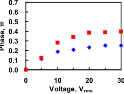
The phase shift of T-PNLC as a function of an applied voltage with different cell gaps is shown in Figure 7. The phase shift of T-PNLC with the cell gap of 5μm is around 0.25π radians and the phase shift of T-PNLC with the cell gap of 7μm is around 0.4π radians. The phase shift increases when the cell gap of T-PNLC increases. However, when the curing voltage is fixed, the thicker cell gap of T-PNLC causes more serious scattering effect. For obtaining a large phase shift, the cell gap and the curing voltage of T-PNLC should be adjusted and optimized.
0.0 0.1 0.2 0.3 0.4 0.5 0.6 0.7 0 10 20 30 Voltage, Vrms P h ase , π
Figure 7 : The phase shift as a function of voltage for T-PNLC with the cell gap of 5μm (blue diamonds) and T-PNLC with the cell gap of 7μm (red squares).
4. CONCLUSION
A polarization-independent liquid crystal (LC) phase modulation using T-PNLC is demonstrated. The mechanism of T-PNLC belongs to the double-layered type. The three sub-layers structure in T-PNLC should be preserved with high curing voltage. The T-PNLC with curing voltage 0Vrms acts as a TN cell and should be applied very high voltages to achieve polarization independent and to avoid scattering. The phase shift of T-PNLC depends on the curing voltages and cell gaps. The phase shift of T-PNLC is 0.4π radians when the curing voltage is 2.5 Vrms and the cell gap is 7μm. To further enlarge the phase shift, we can enlarge the cell gap and choose the proper curing voltages. The potential applications are spatial light modulators, laser beam steering, and micro-lens arrays.
The authors acknowledge support from the National Science Council (NSC) in Taiwan under the contract no. NSC 101-2112-M-009 -011 -MY3.
REFERENCE
[1] McManamon, P. F., Dorschner, T. A., Corkum, D. L., Friedman, L. J., Hobbs, D. S., Holz, M., Liberman S., Nguyen, H. Q., Resler, D. P., Sharp, R. C. and Watson, E. A., “Optical phased array technology,” Proc. IEEE 84, 268 (1996). [2] Lin, H. C. and Lin, Y. H., “A fast response and large electrically tunable-focusing imaging system based on switching
of two modes of a liquid crystal lens,” Appl. Phys. Lett. 97, 063505 (2010).
[3] Lin, Y. H., Chen, M. S. and Lin, H. C., “An electrically tunable optical zoom system using two composite liquid crystal lenses with a large zoom ratio” Opt. Express 19, 4714-4721 (2011).
[4] Lin, H. C. Lin, Y. H., “An electrically tunable-focusing liquid crystal lens with a built-in planar polymeric lens” Appl. Phys. Lett. 98, 083503 (2011).
[5] Lin, H. C., Chen, M. S. and Lin, Y. H., “A review of electrically tunable focusing liquid crystal lenses,” Trans. Electr. Electron. Mater. 12, 234 (2011).
[7] Ren, H., Fan, Y. H. and Wu, S. T., “Prism grating using polymer stabilized nematic liquid crystal,” Appl. Phys. Lett. 82, 3168 (2003).
[8] Efro, U., [Spatial Light Modulators], Marcel Dekker, New York, (1994).
[9] Lin, Y. H., Ren, H. and Wu, S. T., “Polarisation-independent liquid crystal devices,” Liq. Cryst. Today 17, 2 (2009). [10]Lin, Y. H., Ren, H., Fan, Y. H., Wu, Y. H. and Wu, S. T., “Polarization-independent and fast-response phase
modulation using a normal-mode polymer-stabilized cholesteric texture.” J. Appl. Phys. 98, 43112 (2005).
[11]Ren, H., Lin, Y. H., Wen, C. H. and Wu, S. T., “Polarization-independent phase modulation of a homeotropic liquid crystal gel,” Appl. Phys. Lett. 87, 191106 (2005).
[12]Ren, H., Lin, Y. H., Fan, Y. H. and Wu, S. T., “Polarization-independent phase modulation using a polymer-dispersed liquid crystal,” Appl. Phys. Lett. 86, 141110 (2005).
[13]Lin, Y. H., Ren, H., Wu, Y. H., Zhao, Y., Fan, J. Y., Ge, Z. and Wu, S. T., “Polarization-independent liquid crystal phase modulator using a thin polymer-separated double-layered structure,” Opt. Express 13, 8746 (2005).
[14]Ren, H., Lin, Y. H. and Wu, S. T., “Polarization-independent and fast-response phase modulators using double-layered liquid crystal gels,” Appl. Phys. Lett. 88, 61123 (2006).
[15]Lin, Y. H. and Tsou, Y. S., “A polarization independent liquid crystal phase modulation adopting surface pinning effect of polymer dispersed liquid crystals,” J. Appl. Phys. 110, 114516 (2011).
[16]Lin, Y. H., Chen, H. S., Lin, H. C., Tsou, Y. S., Hsu, H. K. and Li, W. Y., “Polarizer-free and fast response microlens arrays using polymer-stabilized blue phase liquid crystals,” Appl. Phys. Lett. 96, 113505 (2010).
[17]Huang, Y., Wen, C. H. and Wu, S. T., “Polarization-independent and submillisecond response phase modulators using a 90° twisted dual-frequency liquid crystal,” Appl. Phys. Lett. 89, 021103 (2006).
[18]Lin, Y. H., Chen, M. S., Lin, W. C. and Tsou, Y. S., “A polarization-independent liquid crystal phase modulation using polymer-network liquid crystals in a 90 twisted cell,” J. Appl. Phys. 112, (2012).(in press)