ELSEVIER Mechanics of Materials 24 (1996) 175-198
M K H A N I C S
OF
MATERIALS
The stress intensity factors of regularly and singularly
perturbed-interface cracks
C h a o - H s u n C h e n *'l J i n h o n H s u 2 Institute of Applied Mechanics, National Taiwan University, Taipei, Taiwan
Received 25 September 1995; revised version received 18 July 1996
Abstract
As we know, many composite failures occurring at interfaces, such as between thin-film and substrate or fiber and matrix, are mostly induced by the crucial far-field lateral stresses parallel to the interfaces. Among various mathematical models representing real cracks, the 'thin cut' model is of special interest, since it requires the simplest mathematical methods in its study. This model, however, can not reflect some properties of real cracks. Especially, when the crack is uneven. In this case, the far-field lateral stresses may dominate the fracture mechanism of uneven interface-cracks. But using the thin-cut mathematical analysis can just show zero stress intensifying phenomenon at the tips. The present paper adopted a modified mathematical model of an interface crack with smoothly perturbed surface to study the different mechanism between the flat thin-cut and the perturbed-interface crack. The Hilbert's problem presented in this paper enables us to describe the different perturbed-interface cracks. Via this representation the perturbed-interface crack problem then can be solved in a unified manner. A perturbation analysis technique based on the idea of Muskhelishvili's potential formulation in conjunction with the homogeneous and general Hilbert's problems to derive the solution is presented. The asymptotic solution for the title problem under the general uniform far-field stresses is obtained for the first order of unevenness. When the far-field lateral stresses are much larger than the others, due to the above mentioned reasons, the corresponding solutions are most concerned and explicitly presented to analyze how the lateral stresses affect the stress intensity factors as the crack face is uneven.
1. Introduction
T h e i m p e t u s to u n d e r t a k e this w o r k c a m e f r o m the recent e x p e r i m e n t a l and t h e o r e t i c a l i n v e s t i g a t i o n s o f several r e s e a r c h groups, to o n e o f w h i c h the writers b e l o n g , on fracture b e h a v i o r s o f t a k i n g u n e v e n n e s s o f crack face and local g e o m e t r y b e h i n d c r a c k tip into a c c o u n t . T h e s e p h e n o m e n a o b s e r v e d in m a n y studies a l w a y s exist o f an i n t e r f a c e o f b i m a t e r i a l and p e r f o r m an i m p e r f e c t b o n d i n g . T h e e f f e c t s o f u n e v e n n e s s and local g e o m e t r y are t h e r e f o r e e m p h a s i z e d in this paper.
* Corresponding author. Tel.: + 886-2-3630979; fax: + 886-2-3639290. i Associate Professor.
2 Graduate student.
0167-6636/96/$15.00 Copyright © 1996 Elsevier Science B.V. All rights reserved. PH S 0 1 6 7 - 6 6 3 6 ( 9 6 ) 0 0 0 3 6 - 1
176 C.-H. Chert, J. Hsu / Mechanics of Materials 24 (1996) 175-198
Another fact motivating the present work is that the interface structures of f i b e r - m a t r i x composites or thin film-substrate composites mostly fail or debond under certain crucial far-field lateral stresses. This fracture phenomenon is impossible to analyze, if the interface crack is traditionally assumed to be a flat thin-cut, mathematically, the stress intensity factors are never affected by the lateral stresses. For these reasons, the effect of unevenness of the crack faces must be taken into account to determine the practical stress intensity factors and to predict the real interface fracture behaviors. A modified interface crack with smoothly perturbed surfaces ensures not only good agreement with reality, but also can retain mathematical simplicity. Therefore, the present paper is mainly using this mathematical model to study the different mechanisms between the flat thin-cut and the perturbed-interface crack. As the main problem we consider the two-dimensional elasticity problem of a perturbed-interface crack lying along the interface of two bonded dissimilar half-planes. In contrast to other approaches in the literature, the Hilbert's problem presented in this paper enables us to describe the different perturbed-interface cracks. Via this representation the perturbed-interface crack problem can be solved in a unified manner.
When cracks grow in non-uniform stress fields, the path of the fracture is generally curved, or a new crack will initiate at an angle of the old one. Much effort has been put to crack initiation at an angle to a pre-existing crack. Lo (1978) presented a convincing solution that models the crack as a continuous distribution of dislocations, in a manner that can handle both finite and infinitesimal kinks. Cotterell and Rice (1980) proposed a solution for the elastic stress intensity factors at the tip of a slightly curved or kinked two-dimensional crack. Their solution is accurate to the first order in the deviation of the crack surface from a straight line and is carried out by perturbation procedures analogous to those of Goldstein and Salganik (1974). Karihaloo et al. (1981) presented an approximate description for the slightly out-of-plane growth of a straight crack under mixed-load- ing and in the presence of an in-plane stress. They concluded that the influence of the in-plane stress on the stability of the crack growth is the same as those reported by Cotterell and Rice. For a finite body the crack branching, curving and path stability can be referred to Sumi et al. (1983); Sumi et al. (1985). Movchan et al. (1987) used asymptotic methods to compute the stress intensity coefficients at the tips of a thin cut with smoothly closing edges and the asymptotic form of the potential energy. Wu (1994) defined perturbed cracks in a homogeneous m e d i u m with y = e Y + ( x ) where
I xl
-< 1 land e is a small parameter, which denote the upper and lower surfaces of a hole in a nondimensionalized rectangular Cartesian coordinate system ( x , y). For e not equal to zero, the hole is called a regularly (singularly) perturbed crack if Y~_(_+ l ) =Y'(+
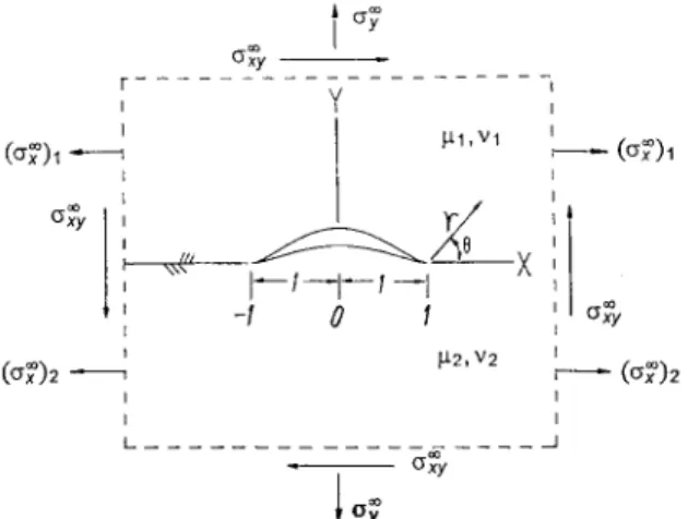
1) (Y~_(+ 1 ) ~ Y'_(+ 1)). In W u ' s work, unevenness of crack face was considered in both regular and singular cases, and its effects were shown in the stress intensity factors. The notch-tip singularity associated with a singularly perturbed crack is also obtained by the method of matched asymptotic expansions.In this paper, regularly and singularly perturbed-interface cracks are analyzed. The problem configuration is depicted in Fig. 1, which shows the upper and lower surfaces of a hole, the interface, the loading at infinity, and the nondimensionalized rectangular Cartesian coordinate system ( x , y). In the upper half-plane, the shear modulus is /x I and Poisson's ratio is t, 1. In the lower half-plane, the shear modulus is /x 2 and Poisson's ratio is ~'2- The interface could be described with two straight bonded lines and a perturbed-interface hole, which are defined by Cb:
y=O
C,: y = e Y + ( x )
Cl:
y= eY_( x)
wherer+(x)
- r _ ( x ) _ 0 , r + ( + l ) = r _ ( + l ) = o , x ~ ( - o % -- 1] t_J [1, ~c), bonded lines, x ~ ( - 1, 1), upper surface of hole, andx ~ ( - 1, 1), lower surface of hole,
(1.1) (1.2) (1.3)
( 1.4) (1.5)
C.-H. Chert, J. Hsu / Mechanics of Materials 24 (1996) 175-198 177
and 8 is a small parameter. As s tends to zero, the perturbed-interface crack degenerates into a straight crack of length 2. The functions Y±, together with their derivatives, are continuous.
A perturbed-interface crack is called 'regular' if
Y~.(_+I) = Y_(_+ 1)' = 0, (1.6)
which ensures the existence of cusps at x = + 1. For such cases, the perturbation procedure used is a regular one in that all asymptotic expressions are uniformly valid throughout the region of interest. If Eq. (1.6) could not be satisfied, then the perturbed-interface crack is called 'singular' and the required singularities of stresses around the tips can not be determined from the regular perturbation procedures. For this reason, the asymptotic expansions must be constructed for different local geometries of the tips and the coefficients of the asymptotic expansions can be determined by matching the near-tip asymptotic expansions and the global perturbation solutions. The condition defined in Eq. (1.6) to distinguish the regular cracks from the singular ones is more stringent then the one has been used in Wu (1994). That is because the crack exists in the bimaterial interface, rather than in a monolithic material. In a monolithic material, the crack remains regular provided that Y~_(_+ l ) = Y'(_+ 1), i.e. the crack has close-type tips. But, for the interface crack, its upper and lower faces must have vanishing derivatives at the tips, then it can be called regular. When the two materials become the same in the bimaterial problem, the solutions of the selected regular case, as we present in this paper, reduce to the ones shown in Wu (1994), and the regular condition also changes to be the one used for the crack existing in a monolithic material.
Complex variable and perturbation analysis are the basic concepts which were used to formulate and study the problem considered in this paper. Homogeneous and general Hilbert's problems are obtained for solving the perturbed-interface cracks. But the functions Y± appearing in the Hilbert's problems must be known a priori, otherwise only integral forms can be found. Hence, some special cases simulating practical failures are chosen to demonstrate all the solving processes and give some referable results. For regular cases, perturbed-interface holes with cusps are selected. The explicit solutions, including local singularities, of these examples can be determined by regular perturbation analysis without further difficulties. And the solutions can be reduced to the same results found in Wu (1994) when the materials are the same. For singular cases, perturbed-interface holes with notch-tips are used to demonstrate. Perturbation solutions satisfying boundary conditions and interface continuity conditions are solved and named outer solutions to represent the global behaviors but the near-tip singular characters. Inner solutions, the near-tip asymptotic expansions, whose coefficients must be matched out by outer solutions, need a close form expression for the matching purpose. Hence, the numerical schemes and results presented in Bogy (1971); Hein and Erdogan (1971) are not valid in this paper. But deriving a close form expression for determining the singular characters in two edge-bonded elastic wedges of different materials and wedge angles seems impossible in present days. In this paper, a small notch existing in the interface of bimaterial is considered and derivation procedures of Williams (1959) are used to solve the near-tip problem. This way we derived at an expression of combining leading singularity with perturbation concepts. This expression reveals the relationship of material combination, small notch angle and leading singularity, and is utilized to match the outer solution after neglecting the higher order terms. The coefficients of asymptotic expansions are then obtained. Hence, the complete solution to a singular perturbed-interface crack is obtained.
2. Complex variable formulation
Muskhelishvili (1953) and others have shown that the solution to an individual problem in the plane theory of elasticity can be reduced to finding two independent complex functions, which satisfy the boundary conditions of the problem. In the case of two different materials, however, the elastic properties are discontinuous across the bonded line, and a complete solution to the problem requires the knowledge of four complex functions,
178 C.-H. Chen, J. Hsu / Mechanics of Materials 24 (1996) 175-198
(~)~
-(o~)2
. F . . . , Y I I I "xx xff/ X ' I ~ / ~ 1 ~ 1 --1'
-1 0 1 I ~ 2 , V2 F,
I_ . . . ~ 1 , V 1 - (~)1Fig. 1. Infmite bimaterial-plate with a perturbed-interface hole subjected to stresses at infinity.
Wj(z) and f j ( z ) j = 1, 2, of the complex variable isotropic elasticity in the forms used by England (1971) are
( O"y)j -
i(O'xy)j ~- 14:}.(z) '~ Wf(z) Jv ( z - z)Wff(z) - f j ( z ) ,
2 p q ( u , + i u 2 ) j =
KKjWj( z) -- Wj(z) + ( z - z)W/( z) + fj(z) and
iRj = Wj( z) + Wj(-z) + ( z - z ) W / ( z) - f j ( z ) ,
z = x + i y . The basic equations for the two dimensional
(2.1)
(2.2)
(2.3)
where (u I, U2) j are displacement components, (o-,)j, (try)j, (tr, y)j are stress components, ~z i is the shear modulus, K~ = 3 - 4vjl for the plane strain and Kj = (3 - v j ) / ( 1 + vj) for the generalized plane stress, and vj is the Poisson ratio. Also R j = ( R I + i R z ) j is the resultant force, W / ( z ) ,wj(z)
represent the derivatives of Wj(z), w/(z) with respect to z, respectively.The infinite plane o f bimaterial is subjected to uniform far-field stresses as shorn in Fig. 1. A notable condition is that the stress o-~ is discontinuous across the interface, i.e., (tr~)l ~ (trY)2- Thus, it is necessary to distinguish (tr~)l in the upper region from (o:~) 2 in the lower region. In fact, they are related to each other by Eq. (4.21) which is derived from the conditions of continuity of stresses and displacements across the x-axis along which the component o-~ has a jump. With this relation the continuity conditions along the bonded lines are then satisfied such that this elasticity problem of bimaterial can be solved without further difficulties.
The interface between the two media involves two parts, one is the bonded part including x _< - 1 and x _> 1 called Cb; and the other is the perturbed-interface crack in - 1 < x < 1. x between - 1 and 1 will be replaced by x* in the following sections of this paper to distinguish the perturbed pan from the bonded pan. It is assumed that C b is perfectly bonded so that tractions and displacements along it are continuous. Hence, we obtain two continuity equations as shown in Eqs. (2.4) and (2.5). In particular, the traction continuity condition may be integrated once to become a continuity condition in R (cf. Eq. (2.3))
W l ( Z ) "[- W l ( ~ ) -[- ( Z - - z ) W ; ( Z ) - - / l ( ~ ) = W 2 ( Z ) + W2(~ ) -Jr (Z -- z ) W ~ ( Z ) - f z ( z ) ( 2 . 4 )
and
W l ( z ) = "yW2(z) + y * [ W 2 ( z ) "[- W2(z) -[- ( z - z ) W ~ ( z ) - f 2 ( ~ ] , (2.5) where Eq. (2.4) represents the continuity condition in R, Eq. (2.5) shows condition which is simplified by using
C.-H. Chen, J. Hsu / Mechanics of Materials 24 (1996) 175-198 1 7 9 Eq. (2.4), and z is along the bonded interface. Two constants, Y and 3' *, appearing in Eq. (2.5) are composed of four material constants
* ' ( " ' )
(1 +~:2)/Xl a n d y - - - 1 - - - . (2.6)
T = (1 + Kl)tx 2 1 + K l /x 2
The constants 3' and y * are related to Dundurs' constants a and /3, via (Dundurs, 1969)
y - 1 2 y * + y - 1 l + a /3-o~
a = - - , /3 o r y - , y * - - - ( 2 . 7 )
y + l y + l 1 - o r 1 - o e
In addition, the traction-free condition is assumed along the crack faces Y+. This assumed condition is also integrated once to become the vanishing of R. From Eq. (2.3), we have
W,(z) + W,(z) + (z - z ) W ; ( z ) - f , ( z ) = 0 and
W2(Z) + W2(z ) + (Z - z)W~(Z) - f 2 ( z ) = 0 where z is along the crack faces.
(2.8)
(2.9)
3 . P e r t u r b a t i o n a n a l y s i s
Based on the perturbation theory, the four complex functions Wj(z), fj(z) are rewritten as Wi( z; 6), w2( z; 6) j = 1,2 after involving the perturbation variable 6, and they can be expressed in powers of ~ as follows:
wj( z; 6) - E
(3.1)
n = 0 " oo ~ n
fj( z; 6) - E 7 f j . ( z ) .
(3.2)
n = 0 "
The perturbed-interface crack with its upper and lower boundaries is given by Z = Z * + = x * + i ~ Y _ + ( x * ) ,
where e is a small dimensionless parameter. Y + ( x , ) and Y _ ( x * ) are the upper and the lower surfaces of the perturbed-interface crack, respectively. We assume that Y_+(x*) and Y~ (x*)are smooth and continuous such that there is no additional singularity other than the ones at x* = _+ 1.
Thus, Win(z? ~ ) and W1,(~-7) can be expanded as follows:
Wl~( z_~ ) ~ W~-~( x* ) + icY+ ( x* "~W '+ : 1, ( x * ) + O ( e 2 ) , (3.3)
w1.(7S2) ~ WL( x* ) - iEY+( x* ) w ; ; ( x* ) + 0 ( 6 2 ) . (3.4)
Similar expansions are also found for W2,( z_* ), W2, z(-2-_*, f l , ( z_~ ),fi ,(~-), f2,(~-) and f:,(TS).
Let z~_ and z* replace z in Eqs. (2.8) and (2.9), respectively. We have two equations for the traction-free condition along the boundary of the perturbed-interface crack, which are shown in Eqs. (3.5) and (3.6).
W,( z~ ) + W1(~-+) + i2eV+ ( x* )W;( z.~ ) -f,(~+-+) = 0, (3.5)
W2( z_~ ) + W2(z-~-_* ) + i2eY+ (x*)W~( z_* ) - f : (z-~-_*) = 0. (3.6) Substituting Eqs. (3.1) and (3.2) into Eqs. (2.4) and (2.5) and letting z = x yield four Eqs. (3.7) and (3.8), Eqs. (3.11) and (3.12). Four other equations are also obtained by substituting suitable expansion forms, like Eqs.
180
C.-H. Chen, J. Hsu / Mechanics of Materials 24 (1996) 175-198(3.3) and (3.4), into Eqs. (3.5) and (3.6). Therefore, two groups of equations corresponding to the orders of e0 and e I are classified as follows:
E0:
W~o ( x ) + W ~ ( x ) - f~(o(x) = W~o ( x ) + W2o ( x ) - J~-2o(x), (3.7)
W~o ( x ) = TWO-o(x) + 3'* [W;o ( x ) + W2o ( x ) -f2zo( x ) ] , (3.8)
W~o ( x* ) + W~-o( x* ) - fl(o( x* ) = 0 and (3.9)
W;o( x* ) + W;o( x* ) - ~ o ( x* ) = o.
(3.1o)
~.1:
W~l( X ) + W?l( x )
-f~(,(x) = W~-,(x) +W;,( x) -F2,( x),
(3.11)W ~ ( x ) = 3"W;,(x) +
3"* [ W~'I(x) + W~I ( x ) - J'2-21( x ) ] , (3.12)[w~(x*) + w;-~(x*) - ~ ( x* )] + it+( x* )[W(o (x*)
+ 2w(o ( x * ) - W(o(X* +flo( x*)] = 0
and (3.13)[ W ; ( x * )
+ W ; , ( x * )
-)~-2,(x* )1+iY_(x*)[W~o(X* + 2 W ~ o ( X * ) - W ~ o ( X * )
+ J ~ o ( X * ) ] = 0 ,(3.14) where the Eqs. (3.7), (3.8), (3.11) and (3.12) come from the continuity conditions along the bonded interface, and the Eqs. (3.9), (3.10), (3.13) and (3.14) from the traction-free condition on the crack faces.
4. Basic solution to the order of e 0
w,k(z)
w~,(z)
3"+3" [ 1 f,t,(z) = 1 - - T[1
fzk(Z) =
3* 3"+Eqs. (3.7), (3.8), (3.11) and (3.12) can be written together as follows:
W~-k(x) - W~-k(x) +3'~-2k(x) = W~-k(x) - W~-k(x) + f~(k(x), (4.1)
W~-k(x) - 3'* [W2k ( x ) - f2-2k( x)] = ( 3" + y* )Wfk ( x ) , (4.2)
where k = 0, 1.
According to Eqs. (4.1) and (4.2), new complex functions ~k(z) and ifk(z) are designated to be
~ k ( z ) = Wik(Z) -- W2k(Z) +f2k(Z) = W2k(Z) -- W1k(Z) + f l k ( Z ) , (4.3)
t i c k ( Z ) ~- W i k ( Z ) --
3"* [W2k (Z)
- f 2 k ( Z)] = (Y+ 3"* )W2k(Z),
(4.4)
where ~k(z) and aP'k(z) will satisfy qb~-(x)= ~ - ( x ) and i f ~ - ( x ) = if~-(x). Then, we can conclude that @k(z) and if'k(z) are holomorphic functions in the whole complex plane cut along - 1 to 1 on real axis.
Furthermore, the functions Wik(Z),
W2k(z),fik(Z) and f2k(Z)
can be expressed with ~k(z)and ifk(z).1 1 - 3"* [ i f k ( z ) - 3" *q0k( z)], (4.5) 1 , ~ k ( z ) , (4.6) 1 ] _ _ 1 - 23'* q~k(z) and (4.7)
~ + 3 . i f , ( z ) + 1-3"*
]
1 1 - 3 " * i f k ( z ) + 1 - 3 , * ifk(z)" (4.8)C.-H. Chen, J. Hsu / Mechanics of Materials 24 (1996) 175-198 181 Manipulations between Eqs. (3.9)
and @o(X*), and the other between ~ - ( x * ) and ~o(X* ). Eq. (3.9) subtracted by Eq. (3.10) yields
[W,~( x* ) - W;o ( x* ) + ~ o ( x* )] - [W~o ( x* ) - W~o + f ; o ( x* )] = 0, and adding the two Eqs. (3.9) and (3.10) yields
[W:o(X*)
+W;o(X*)
-~o(X*)] + [W2o + (x*)
+WVo(X*)
-~o(X*)] =o.
With the definition in Eq. (4.3), Eq. (4.9) reveals the first relation.
• ~ ( x * ) - ~o(X*) =0.
Eqs. (4.5), (4.6), (4.7), (4.8) and (4.1
~,~(x*) + Aq, o(X') = ~ ( x * ) ,
where A = (1 - y * )/(3' + Y * ).
and (3.10) will give us two relations which include one between q ~ ( x* )
(4.9)
(4.10)
(4.11) 1) and the definition in Eq. (4.4) makes Eq. (4.10) give the second relation.
(4.12)
1
q'0(z) = - - n z + P x ( z ) ,
I + A
where P is also a complex constant, x ( z ) = ( z 2_
1)l/2(z + 1/i~
z
---:S j and
1 ~ = 2~rln(A). (4.17) (4.18) (4.16) With the same procedures used to find Eqs. (4.11) and (4.12), manipulations between Eqs. (3.13) and (3.14) give us the following two relations:q)~ ( x* ) - qb-~ ( x* ) = - i Y + ( x* ) [ W ( o ( X* ) + 2W(o(X* ) - W;o ( X* ) + f ~ o ( X * ) ]
+ir_(x*)[W;o(X*) + 2W;o(X*)-w;o(x*)
+ ~ 0 ( x * ) ] (4.13)and
2 [ ~ - ( x * ) + A ~ - ( x * ) ] = (1 + y * ) ~ - ( x * ) + (1 - V*)q0]-(x*)
- i(1 - y * ) ( r + ( x * ) [ W ( o ( x * ) + 2W(o(X* ) - W ( o ( X " ) +f~jo(X*)]
l + * i t * I -
+ Y - ( x * ) [ W 2 o ( X ) + 2 W ~ 0 ( x ) - W ~ o ( X * ) + f ~ 2 o ( X * ) ] ) . (4.14) Eqs. (4.11) and (4.12) were used to find the basic solution to the order of e °, Eqs. (4.13) and (4.14) were then used to find the solution to the order of e i. Eqs. (4.11) and (4.12) are the homogeneous and general Hilbert's problems, respectively. Referring to the solutions of Hilbert's problems by England (1971), these problems can be solved without further difficulties. After obtaining the basic solution to the order of e °, the solution to the order of e l, however, can be solved from Eqs. (4.13) and (4.14) when the profile of the perturbed-interface crack Y+(x* ) is given.
First, the basic solution to the order of e ° must be solved because it is valid for different types of perturbed-interface cracks, and it can be examined by the well-known results obtained in Rice and Shih (1965).
The solution of Eq. (4.11)is
qbo( z) = BZ, (4.15)
182 C.-H. Chen, J. Hsu / Mechanics of Materials 24 (1996) 175-198
Let the boundary condition at infinity be satisfied, the complex constants B and P will be evaluated and a notable relation between (0-7) 1, (O-x) 2 and try can be obtained.
1 - y *
P = 1 +-A [try -iO-xy ], (4.19)
l + y ~ •
e ~- - - - ~ [( ovx~c)2 -]- OVy ] -- ( 1 -- ' ~ )O'y a n d (4.20)
1
(o'~) 2 = --~ [(~r~) t + (1 - y - aT* ) o ' f , (4.21)
where the imaginary part of B is neglected, because this part will not influence the stress field. Eq. (4.21) is the same as Eq. 19 in Rice and Shih (1965), and it reveals the relation of the far-field stresses under the assumption of the continuity condition along the bonded lines.
Thus, the four complex functions Wlo(z), W2o( z),flo(z) and f20(z) are determined by Eqs. (4.5), (4.6), (4.7), (4.8), (4.15) and (4.16).
W,o ( z ) = aloz + B, o X ( z ) , (4.22)
W2o(z) = a20 z + B2o X ( Z ) , (4.23)
flo(Z) = C,o Z + O,o X ( z ) and (4.24)
f2o(Z) = C2o z + O2o X ( z ) , (4.25)
where
A10 =
O l 0 =
Y 1 1 1 2y
B, Bio P , A2o = B,
B2o
P , Clo = - - B ,1 + 7 1 - 7 " 1 + 7 7 + 7 * 1 + 7
7 + 2 7 * - 1 2
P , C20 = B and
020-~ --Ol0.
(1 - y * ) ( ~ , + y ' ) l + yWhen the four functions Eqs. (4.22), (4.23), (4.24) and (4.25) are obtained, the solution to the order of e0 is finished. All of the physical quantities, such as stresses and displacements, can be derived from these functions to the order of e °. In the following sections the solutions to the order of 6 ~ for the regularly and singularly perturbed-interface cracks are then considered and solved with their given crack profiles. Their corresponding stress-intensity-factors are also determined.
5. Solutions to the order o f e I for the regular case
With Eqs. (4.22), (4.23), (4.24) and (4.25), expressions of W~0(z) and fj0(z) J = 1, 2, Eqs. (4.13) and (4.14) can be used to find the solution to the order of ~l for any interesting perturbed-interface crack if the profiles of crack Y+_(x* ) is known.
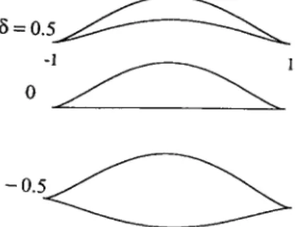
5.1. Holes with cusps (Y+ - Y_ > O)
In this case the profile of the perturbed-interface crack will be simulated with
Y + ( X * ) = (1 - - X ' Z ) 3/2 and Y _ ( x * ) = 3(1 - - x ' Z ) 3/2, (5.1)
C.-H. Chen, J. Hsu / Mechanics of Materials 24 (1996) 175-198
8 = 0 . 5 ~
-1 1
183
- 0 . 5 ~
Fig. 2. Schematics of holes with cusps.
Some of such holes are depicted in Fig. 2. The functions selected in Eq. (5.1) have some characteristics. The power 3 / 2 ensures that the crack faces have vanishing derivatives at _ 1, and makes such cracks regular. The parameter 6 involved in the expression of Y- can create some different configurations of regularly perturbed- interface cracks with its changeable values. And the expressions, which are used here to simulate the regularly perturbed-interface cracks for the purpose of demonstration, are essentially simple and useful to make the desired solutions easy to carry out, without loss of generality.
With the selected functions in Eq. (5.1) and the obtained zero-th order solutions, Eqs. (4.13) and (4.14) can be presented as
l+x,/i`"
~ ; ( x * ) - - ~ 7 ( x * ) = i A 4 , ( 1 - x * 2 ) 3 / 2 + i [ B c ~ ( 1 - x * ) +C~(1 + x * ) ] ( 1 - x .2) 1_--7~ ] +i[B--~(1-x*) +C--~(1 + x * ) ] ( 1 - x ' a ) ( 1 + x * / -i"t 1
_ i - L ~ /
and 2 a 3 " - a - 3' 2 a 3 " - a + 1 2[gc~-(x*) + A ~ - ( x * ) ] = q~-(x*) +CPl(X* ) +
i4 B(1 - x*2) 3/2 + i 1+3" l m 3 " * 1 - I - x * /i`" × a ' / 2 P [ ( 2 o t - i ) ( 1 - x * ) + ( 2 a + i ) ( 1 + x * ) ] ( 1 - x .2) 1_---7-77 ]263"* - 8 + 1
+ i
1 - 3"*
a ' / 2 ~ [ ( 2 ~ + i ) ( 1 - x * )
/ , + x , l '°
+ ( 2 a - i ) ( l + x ' ) ] ( 1 - x * 2 ) ~ l - - 7 7 ] , where 4 ( 6 - 3') 2 ( 6 + 1) 2 ( 8 + 1) A¢,- 1 + 3" B, B ~ - 3"+ 3"*y - ' / Z ( o t - i l ) P a n d C ,
-
3---~---3",
The following functions will appear in the solutions of Eqs. (5.2) and (5.3):
K ( z ) = (z 2 - 1) '/2,
rz+,)
L~(z) Z--] ~ - l J
1 - ( z + i 2 a + l ) ( z + l ) - ~ t z - - ~ - '3" '/2(,,+i~)P
(5.2)
(5.3) (5.4) (5.5)+ X I X +
?
+
_'--"
~q...--.
g
~?1
~
÷
-
~-. + ~ --.-4- ~ I -t- I ~a ~j ~ ba - ~ ~ ~ \._.
/'-I II I bJ I + + t.m --., I + - + +-I
+ ~ bl + /xl bo + I2"
++
+
+ ~ ~" ,~ + ' , I I + +©
g
+ + I Ii!
e'~ I;q
i + + ~~1"
4
~ + i i + ~ + + + ~ ~ - + i i + - ~+ + + ~ ~ ~-, v I ¢~ -I- Jr" I I ,., i ~ ~ + ~ / + I ~ ~ o _. + ~ ~ ~ ~ ~' 0 -" I I + I + ~ + ~- _ + ~?1
~
- + d ~ ~' IC.-H. Chen, J. Hsu / Mechanics of Materials 24 (1996) 175-198 185
where
/ [ ( 1 - y *
°¢ /
A ~ = ( 2 8 3 , * - 3 - 3 ' ) ~ ~.~)2 + ° ' y ] - 4 +13' O-y ,
2~53"* - 3 + 1
B y = 2(1 + a )
20tffxy+O'y
+ 1 20~O-y--O'xy
,A(263"* - 6 + 1) ~
C,# = -( ~'~-A 3-( -+--f-~ q [ ( -- 2 aO'xy -- O'y ) + i ( 2 oto'y -- O'xy ) ] ,
233"* - 6 + 1
D ~ = 2(1 + A ) [ ( 2 ° t % Y - ° ' Y ) + i ( a a ° ' Y - ° ' x Y ) ] '
A(2•3' * - a + l )
E ~ = ( i + - - ~ i l + A 2) [ ( - 2 c ~ < y + O'y) + i ( 2 c ~ r f + o-x~)] ,
and the polynomials 4, 3 Z 3 q- ~/)2 z2 "l- (/)1Z and ~o 2 z 2 + ~o I z + ~o0 are so chosen that both q)'l(z) and q*~(z) tend
to
O((1/z2))
as z tends to infinity. The coefficients of these two polynomials are therefore determined asfollows: 4 o t A 1/2 4 a 2AI/2 ~b3 = ~A4,, 1 ~b 2 = 0, qb I 3 + R e [ B 6 - C6] - - I m [ B , -- C61 = - ~ A ~ A - I A - I ' l A - l [ 1 A ~/2 )] l + a A , - i + 1 , i 2 a A - 1 AI/Z(A - 1)
91=(Bv+C~+D~+E4,)-i4°t(Eev-C4,)
+ I + A A , + i 2 A 1 / 2 ( A + I) (B¢,+C6) +
( A 2 + 1 ) ( A + I )× [ ( - 4 a + i)B-~6 + (4ee + i)C--~)], and 2 2 a ( a + i ) q°° = 1(1 + 4°t 2) q°2 -- i2 °tq'l -- 1 + - ~ 4 ' + A - 1
A ~ + ( 2 a 2 + i 2 a + l ) ( B ~ - E ~ )
2ot2(A + 1) 2 + i2ot(X 2 - - 6 A + 1) + ( A - 1) 2 + ( 2 a 2 - i 2 a + 1)(6" 6 - D6) + i 2 A ' / 2 ( a 2 - 1) B4' 2 ~ 2 ( )t + 1) 2 • + i 2 a ( 3 a 2 - 2A + 3) - ( a - 1) 2 2 ~ ( c ~ - i ) ( a + 1) 2 + ( a - 1) 2 -- 1 a 4 -- 1 /~1/2~--~__ i 2 ~ . 1 / 2 ( A 2 - 1) C4 • 2 ° e ( c ~ + i ) ( A + l ) 2 - ( a - 1) 2 + l A 4 - 1 AI/2c--~'where Re[ * ] and Im[ * ] represent the real part and imaginary part, respectively.
When the two materials are the same and the parameter 6 = 0, the solutions Eqs. (5.14) and (5.15) can be reduced to the solution of Wu (1994).
1 [ [ z + l \ ]
186
C.-H. Chen, J. Hsu / Mechanics of Materials 24 (1996) 175-198
i
[
(z+l
lj21
2grl(Z) = - ~ - - ~ ( 0 ~ - Oy) (Z 2 - 1)3/2 In z----~] - 2 z ( z 2 - 1 ) ..1_ (O.2 __ O.y ) [ __ 1 3 ~Z + ~ Z + ½ ( Z 2 - 1) 3 3/2] 1 [ ( z + l / ]+iO-xy[--Z(Z2--1)+(Z2--½)(Z2--1)I/2] +--.~io[;
Z ( Z 2 - - 1 ) I n~ _ 1 ] - - 2 Z 2
(5.17) and2~l(z)--cI),(z)=-~(o-y-O'y)
( z 2 - 1~ _ l ] - 2 z ( z 2 - 1 )
--iOx~ [ z ( z 2 - 1 ) - (z 2 - ½)(z 2-1)1/2].
(5.18)
The solutions Eqs. (5.14) and (5.15) are therefore accurate to describe the physical quantities for this case, a hole with cusps, to the order of e 1. The stress intensity factor at the tip of the cusp is then determined with Eqs. (4.15) and (4.16) to the order of e0 and with Eqs. (5.14) and (5.15) to the order of e 1.
The stresses at the immediate vicinity of the tip can be expressed as k
=
r -(I/2)+ia (5.19)°rY+i°xy
~
where the complex expression of K is K~ + K H.
For the sake of using Eq. (2.1), we take the complex conjugate of Eq. (5.19).
g , - i g u = 21/2--~r(1/2)+ic~ [
O'y- iO-xy ] .
(5.20)given below with concise forms.
I~1(Z) =
1A4,(Z2
-
1) 3/2 --1- ~3 z3 31- ~1 z, z - i2o~ + 1 2qzl(z) = A--z-TA~( ' Z 2 - 1)3/2 Z + 1 x( 2z 2 + < z + where 8 - 7 8 - 7 A6 = ( I 7 2 ) ' , I:/) 3 = - - 3' 27z + 1 )i,,
+ m (5.22)2
(q~3Z3 l_ ~lZ)..t_ (Z2__ i )
~
1 ]
A + I (5.23) 3 ( 8 - T) 2 8 7 " - 8 -( m ) 1 , A~= Yl, a'f)l,'~"
47 7
With the solutions obtained in this section, the complex conjugate of K is K t - i K n = v ~ [cos( a In 2) + i sin ( ce In 2)] ( 1 - i2 ce )
X [O'ya--iO'xy] 4-0 ° i-~_ T , (q~2-t-qoi+q00) + 0 ( 0 °2 ) • (5.21) In view of Eq. (5.21) there are only ~o 2 + q~l + q~0, which are the coefficients of the polynomial multiplied by
X(z)
in Eq. (5.15), and material constants appearing in the El term. Hence, the stress singularity at the tip tothe order of e is provided by
X'(z).
For some special fracture-mechanisms in which the lateral stresses dominate, the results derived in this section can be reduced to some simple forms for revealing the effects of the lateral stresses. When the far-field stresses O~y ~ and O-xy are neglected in the present determinations, the complex functions q)l(z) and ~1(z) are
C.-H. Chen, J. Hsu / Mechanics of Materials 24 (1996) 175-198 187
6 - y i 2 ~ ( 6 - - T)
q°2- "~(2"-{- 1) (¢r~)n' q~' 2"(2"+ 1) ( ~ ) n and (2cr2 + 1 ) ( 3 - y ) 2or(or + i ) ( 2 6 y * - 6 - y )
9 ° =
l)
+
2"(a- 1)
(,C)l.
Another important expression which must be carried out is of (A + 1)/(1 - 2' * )(~P2 + q~l + q~0) existing in Eq. (5.21). With the concise results shown above this expression can be found.
A + I 4cr(a + i)(1 + 6 )
1 - 2"* ( ~°2 + qol + q~0) = 1 - 2"- 22'* (crY) l- (5.24)
Based on the result obtained in Eq. (5.24) and the assumption that Cry and o-~ are neglected, the complex expression of the stress intensity factors in Eq. (5.21) becomes
K I - i K I I = s f - ~ [ c o s ( o e l n 2 ) + i s i n ( c ~ l n 2 ) ] ( 1 - i 2 c r ) 4 c r ( c r + i ) ( 1 + 3 ) ] 1 - - ' y - - - 2 y - ] (o~2) l + 0 ( ~ 2 ) . (5.25)
6. Singularly perturbed-interface cracks
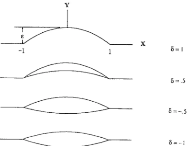
In this section, the upper and lower surfaces of a singularly perturbed-interface crack may be conveniently defined by
Y+(x*)=(1-x
.2) a n d Y _ ( x * ) = 6 ( 1 - x * Z ) , (6.1)where - 1 < 6 < 1. Some of such examples are depicted in Fig. 3.
In view of Eq. (6.1)), Y + ( + I ) # : Y ' ( + 1 ) if 6#: 1; and Y + ( + I ) = Y ' ( + 1 ) ~ 0 when 6 = 1, hence the crack is called singular. The solutions to the order of e °, shown in Eqs. (4.15) and (4.16), are also valid for singular problems, and the solutions to the order of e I would be determined from Eqs. (4.13) and (4.14). But, based on the singular fact, the solutions solved from Eqs. (4.13) and (4.14) is the outer solution which satisfies only boundary conditions. Therefore, in this section, the inner solution representing the local behavior of near-tip structure is also constructed. It has a general expression for different perturbed notch angles and material combinations, and it is suitable for matching purposes. Hence, in solving singularly perturbed-interface
Y -1 1 X ~=1 5=.5 5=-.5
188 C.-H. Chen, J. Hsu / Mechanics of Materials 24 (1996) 175-198
cracks, three main studies including the outer solution, inner solution and matching are approached and shown below in detail.
6.1. Outer solutions to the order of e I for singular examples
4 6 - 3'B
A~, 1 + 3" Ba,,
The solution q~(z) is
With the given functions Y+, Eq. (4.13) becomes
4);(x*)-claT(x*)=i(1-x *~)
Aa, +Ba,~ ~
~,1---77
T]
q'-Ba,l[~) ~,l-x
]
[1 + x * ~'/2( 1 + x * i,~ _ _ [ 1 + x * '~1/2( 1 --l-x* -ia 1
where
6 + 1 6 - 1
- - A - l / 2 ( 2 o e - i ) P a n d C a , ,
-
a - ' / 2 ( 2 a + i ) P .3'+3'* 3'+3'*
~ l ( Z ) = (1 -- za)ln z - 1 - - + - - ( 1 - z Ba,, 2 ) z-- 1 + - - ( 1 - Z Ba,, 2 ) Z - 1
z + l A + I 7 a + l Z - ~
C c a l / 2 ( l _ z 2 ) ( z + l ) ( ' / 2 ) + i "
Ca,A1~2
( g-'l'- 1 ] (1/2)-i~- - 1 -- Z 2 ) + @12 z2
Z + l tZ--'77i - a + l Z----'7"i -] + ~ , , Z ,
where the constants q~12 and q~11 are chosen such that q~l(z) tends to
O((1/z:))
as z tends to infinity2AJ/2 2al/2
qb,2 A~, +217. A + 1 Re[
Ba,, -Ca,,] ,
qg, ,
- - R e [ 1 - i 2 a ) ( B a ,
+ 1
Moreover, Eq. (4.14) becomes
2 [ ~ - ( x * ) + A~7 ( x* )] = iA~l(1 - x* 2) + @ (1 - x* 2)ln 1 - x * - - I + x * + iBm, (1
-x* 2)(l-x*)
(l/2)-ia-I
q-X*
-- ) 1 1 _-i---~7 + iD.,(1 - x* 2) / 1--~Tx. / + i E ~ , ( 1 - x .2) 1_-i--2-~] + 2 ( @ , 2 x * 2 + @ , , x * ) , where * A - 1 * - 4(263' - 6 - 3 " ) B ' B q " = B a , ' h + l
+ A _ l / 2 ( 2 a _ i ) 263"
6 + 1 ) Aqq 1 + 3" - - Y + 3' * A - 1 2 6 T * - 6 + 1 - - P , C0' = Ca,' A + 1 + A - I / 2 ( 2 a + i) "/+3'*A -
1
2 6 3 " * - 6 + 1 _
D,, = -Ba,, A +----i + A - ' / 2 ( 2 a + i) P 3"+3'* A - 1 2 6 3 " * - 6 + 1and E,r, = -Ca,, A +---7 + A - ' / 2 ( 2 a - i) P.
3'+.,/*
P,
(6.2)
(6.3)
C.-H. Chen, J. Hsu / Mechanics o f Materials 24 (1996) 175-198
189
The solution ~l(Z) is
2aP'l ( z ) - A +-~1 [(2qb12
_ ia~,)z2+2c192|z+iA~,]_ i
27rA l/2~'B~q( l _ z 2 ) ( z - 1 )
( l / 2 ) - i a ~
ln--z+lZ-1+ i ( 1 -
z2)l z_-SS/
In + - ( 1 - z 2) 1 -~ z - 1 z + l 1-~A -~ ~ - - - ~ ] z
( z - i 4 a - 1 ) )
E~IAI/2
(Z+ 1 )(I/2)+ia(
(Z+ 1 ]i2~(z--i4c~-- 1 ) }
X - l -
z - 1 i----~ (1 z2)~ z_-- ~ z---~-] z - 1
A~,~ 2 [ z - 1 l - A ]
+ ~(1 + A ) ( 1 - z ) l n z + l - i T r l + A
+X(Z)(~llZ+~lo)'
(6.5)where the constants ~F~l and ~10 are chosen such that ~ ( z ) tends to O(@) as z tends to infinity 1
gill = - - l + h ( i A q ", - 2~12) + i A ~ ( h - 1 ) q ' l o - - - ~ 1 2 + i B q ' - C q "
2Aqtl
( A + I ) 2 ' 1 + A ' 7rA '/2 ~-(1 + A ) i2c~q',,.
The solutions q)~(z) and ~ j ( z ) shorn in Eqs. (6.4) and (6.5) will then be taken to calculate the stress and displacement fields. Their derivatives @](z) and qrl(z) with respect to complex variable z, which are directly related to the stress field, have additional singularities except the traditional singularity existing in X'(z) as z goes to the right crack-tip, and the additional singularities are much stronger. For this reason, the stress field derived by q~](z) and ~ ( z ) is exact but not valid in the extreme vicinity of the crack-tip.
6.2. Inner solution to singular problem
A general expression of inner solutions will be constructed for different perturbed notch angles and different material combinations, and this expression must be explicit for matching purposes. The formulation of the inner problem and the processes of derivation are shown below in detail.
The local geometry of the crack-tip of a slightly open crack is depicted in Fig. 4. The inner problem will be solved by following the same procedures described in Williams (1959). Two straight lines with slopes of - e and 6e describe the traction-free boundaries of the material 1 and material 2, respectively. Here 6 is a constant of O(1), which can be assigned any value between 1 and - 1 for different types of free boundaries, and e is a small parameter used to let the geometry behind the crack-tip be a slight opening.
~2
-rrr
gl vl Z6r. 0)
~2 V2
Fig. 4. The crack-tip geomelry.
~2(r, 0)
190 C.-H. Chen, J. Hsu / Mechanics of Materials 24 (1996) 175-198
Based on elasticity, two biharmonic stress functions xi(r, 0) i = 1, 2, are the fundamental solutions in the upper and lower half-planes, respectively. Then all physical quantities such as stresses, strains and displace- ments can be derived by these two stress functions with some usual relations which are available in common books of elasticity. While these two stress functions are the solutions of
V 4 x i ( r , O ) = O , i = 1 , 2 , (6.6)
where
02 1 0 1 02 V 2 = + - - - + - - -
Or 2 r Or r 2 00 2 .
In Williams (1959), typical solutions of Eq. (6.6)) were chosen of the form
x , ( r , 0) = r ' + ~8~(0) = r ' + ' { & s i n ( s + 1 ) O + B , c o s ( s + 1 ) O + C i s i n ( s - 1 ) O + D i c o s ( s - 1)0}. (6.7) The usual relations between stresses, displacements and stress functions are given as
a i = r ' - ' [ 8;'( O) + ( s + 1 ) 8 i ( 0 ) 1 , (6.8) O-o i = r ' - 's( s + 1) 8i( 8 ), (6.9) o-l@ = - sr'-1{~; ( 0 ) , (6.10) 1 i _ , - (6.11) u o - -f~i~i r { - 8 ~ ( 0 ) - (1 + K i ) [ C i c o s ( s - - 1 ) O - D i s i n ( s 1)0} and 1 u i = r ' { - ( s + 1 ) 8 i ( 0 ) -I-(1 + K i ) [ C i s i n ( s - 1 ) O + D i c o s ( s - 1)0}. (6.12) 2/zi
where the prime denotes differentiation with respect to 0, and let s~ = s 2 in order that the four continuity conditions at 0 = 0 are independent of r.
With Eqs. (6.9) and (6.10), the first four boundary conditions for free edges at 0 = a, - b become
8 , ( a ) = 8 ' i ( a ) = 8 2 ( - b ) = 8 ; ( - b ) = 0. (6.13)
Along the bonded line 0 = 0, there are four continuity conditions
8~(0) = 8 2 ( 0 ), (6.14)
8'l(0 )
= 8 ; ( 0 ) , (6.15) 1 1 2/x---7 [- 8 ; ( 0 ) - C , ( I + Kl) ] = 2/x---7 [-- 8 ~ ( 0 ) -- C2(1 + K2)] and (6.16) 1 1 2/*~ [ - ( s + 1 ) 8 i ( 0 ) + D l ( l + K l ) ] - ~ 2 [ ( S + 1 ) 8 2 ( 0 ) + D 2 ( I + K ) ] . (6.17) Substitution of 8 1 ( 0 ) and 192(0) in Eqs. (6.13), (6.14), (6.15), (6.16) and (6.17)) leads to the following eight homogeneous and linear equations with eight unknowns A 1, A 2, B~, B 2, C1, C 2, D~ and D 2A t s i n ( s + l ) a + B l c o s ( s + l ) a + C l s i n ( s - 1 ) a + D l c o s ( s - 1 ) a = 0 , (6.18) a l ( s + 1) c o s ( s + 1 ) a - B j ( s + 1) s i n ( s + 1)a + C l ( S - 1) c o s ( s - 1 ) a - - D l ( s - - 1) s i n ( s - - 1)a = 0,
(6.19) - a 2 sin( s + 1) b + B 2 cos( s + 1) b - C 2 sin( s - 1) b + D 2 c o s ( s - 1) b = 0, (6.20)
A~ + tC l = A 2 +
tC2,
D l = q B z + ( q + T ) D 2 and
Ci = - q A 2 - ( q t - T ) C 2,
where t = ( s - 1)/(s + 1) and q = (s + 1)y*
C.-H. Chen, J. Hsu / Mechanics of Materials 24 (1996) 175-198 191
A 2 ( s + 1) cos(s + 1)b + B2(s + 1) sin(s + 1)b + C 2 ( s - 1) c o s ( s - 1)b + O 2 ( s - 1) s i n ( s - 1)b = 0, (6.21) Bl + Dl =B2 + D 2 , (6.22) (6.23) (6.24) (6.25) A nontrivial solution for the constants will exist, if the determinant of the matrix of coefficients vanishes. It is easy solved numerically finding eigenvalues with the vanishing determinant. In this paper, however, the crack is modeled as an extremely sharp notch by defining a = ~ - - tan-~e and b = z r - tan-1Be. Because - e is the slope of the free edge of the upper half-plane, and it is a small number such that the crack is somewhat different from the conventional straight-line crack. Without loss of generality, neglecting the higher order terms of e in processes, an explicit form of leading singularity could be obtained.
In Eqs. (6.18), (6.19), (6.20) and (6.21)), a and b are replaced by 7 r - tan-le and 7 r - tan- 16e, respectively. Then four equations for the slightly open crack are discovered and shown below.
A,(sin s ~ - e( s - 1)cos sTr + O( e2)} + n l ( c o s sTI" "~ ~o( S "]- 1)sin sTr + O( e2)}
+ Cl{sin sTr-- e ( s -- 1)cos s~-+ O ( e 2 ) } + Dl{COS sTr+ e ( s -- 1)sin s~-+ O(e2)} = 0, (6.26) a l ( - - c o s s~--- ~ ( s + 1)sin s~-+ O ( e 2)} --Bl{--sin sTr+ e ( s + 1)cos s ~ + O(~2)}
+ C l t { - c o s s T r - e ( s - 1)sin sTr+ O ( e 2 ) } - - D l t { - - s i n s T r + e ( s - - 1 ) c o s s r r + O ( e Z ) } = O , (6.27)
A2{sin s ~ - - eS( s + 1)cos sTr + O( e2)} + B2{- cos s r r - e S ( s + 1)sin s~-+ O( e 2)}
+ C 2 { s i n s ~ - e S ( s - 1 ) c o s s w + O ( e 2 ) } + D 2 { - c o s s T r - s 6 ( s - l ) s i n s w + O ( e 2 ) } = O , (6.28)
and
a 2 { - c o s s r r - e S ( s + 1)sin s r r + O ( e 2 ) } + B z { - s i n sTr+ e S ( s + l)cos s~-+ O ( e 2 ) }
+ C 2 t { - c o s s r r - e 6 ( s - l ) s i n s T r + O ( e 2 ) } + D 2 / { - s i n s r r + e S ( s - 1 ) c o s s ~ - + O ( e 2 ) } = 0 . (6.29) Eqs. (6.22), (6.23), (6.24), (6.25), (6.27), (6.28) and (6.29) are combined to find the characteristic equation for eigenvalues by vanishing the determinant of the matrix of coefficients.
In the process of solving the vanishing determinant, each row which is a linear combination is decomposed. Hence the result of determination is
det[M] = det[Ml] - e ( s + 1)det[M2] + e 6 ( s + 1)det[M3] + O ( e 2) = 0.
where M coefficient matrix of Eqs. (6.22), (6.23), (6.24), (6.25), (6.27), (6.28) and (6.29), 0 1 0 0 Ml = sin(sTr) --cos(s~r) 0 0 1 0 1 0 - I 0 0 t 0 - 1 0 - t 0 0 1 0 - q 0 o 1 0 q 0 qt - y
cos(s~-) sin(s~') cos(sTr) 0 0 0
sin(srr) -tcos(sTr) t sin(sTr) 0 0 0
0 0 0 sin(s~-) -cos(sTr) sin(s~-)
0 0 0 -cos(s~') - sin(s~r) - t cos(s-rr)
(6.30) - 1 o - ( q + y ) 0 0 0 - cos(s~') - t sin(s~')
192 C.-H. Chen. J. Hsu / Mechanics of Materials 24 (1996) 175-198 0 1 0 0 M2 = s i n ( s ~ ' ) sin(s~-) 0 0 0 1 0 0 M3 = sin(sTr) - c o s ( s ~ r ) 0 0 1 0 1 0 - 1 0 0 t 0 - 1 0 - t o 0 1 o - q o o 1 o q o q t - T
cos(s~') sin(srr) cos(sTr) 0 0 0
cos(sTr) t 2 sin(s'n') t 2 cos(sTr) 0 0 0
0 0 0 sin(sTr) -cos(sTr) sin(sTr)
0 0 0 - cos(srr) - sin(sTr) - t cos(s~-)
1 0 1 0 - 1 0
0 t 0 - 1 0 - t
0 0 1 0 - q 0
0 1 0 q 0 q t - y
cos(sTr) sin(sTr) cos(sTr) 0 0 0
sin(srr) -tcos(sTr) t sin(srr) 0 0 0
0 0 0 sin(sTr) - cos(sTr) sin(s~-)
0 0 0 - sin( s~" ) cos( s~- ) - t 2 sin( sTr ) The expressions o f each term in Eq. (6.30) are determined as
d e t [ M j ] = ( - l + t ) 2 [ ( l + y ) 2 c o t 2 s T + ( - l + y + 2 y * ) ] ,
d e t [ M 2 ] = ( - 1 + t)a(1 + t ) c o t sTr[y(1 + y ) c o t 2 s T r - 7 ( 3 - y ) - 4 7 * ( 1 - Y - Y * ) ] and d e t [ M 3 ] = ( - 1 + t)2(1 + t ) c o t s T r [ 3 7 - 1 + 4 y * ( 1 - Y - Y* ) - (1 + y ) c o t 2 s~-].
With Eqs. (6.30), (6.31), (6.32) and (6.33), the characteristic equation can be obtained GleSCOt 3 sTr+ G 2 cot 2 sTr + G 3 e s c o t sTr + G a = O, where G l = - 2 ( l + T ) ( y + 6 ), G 2 = ( I + T ) 2, G 3 = 2 1 7 ( 3 - 7 ) - 6 ( 3 7 - 1 ) + 47 * ( 1 - 7 - y * )( 6 + 1 ) ] a n d G 4 = ( - - 1 + 7 + 2 7 * ) 2. - 1 0 - ( q + T) 0 0 0 - cos( s~ ) - t s i n ( s ~ ) - 1 0 - ( q + y ) 0 0 0 - c o s ( s ~ ) t 2 COS( S~ ) (6.31) (6.32) (6.33) (6.34)
Eq. (6.31) is the same as the result obtained in Williams (1959). Eqs. (6.32) and (6.33) indicate the effects to the order of T. Eq. (6.30) is reduced to Eq. (6.34) after neglecting the higher order effects. Eq. (6.34) can not be solved directly and explicitly without taking advantage of the knowledge of eigenvalues which have been found as e = 0 .
Accordingly, the leading singularity here would be decomposed to s o and s l
s = s o + e s 1. (6.35)
In Eq. (6.35), s o is the well-known eigenvalue for the conventional line-crack, sj represents the induced effect by the slight opening behind the crack-tip, and no influence by the higher order terms is included.
After finishing the substitution of Eq. (6.35) into Eq. (6.34), the expression of s~ is then acquired in an explicit function of s o
s, = F ( y , y * , 6 ) s o cot soTr, (6.36)
where
( 1 + 7 ) [ ( 3 7 - 1 ) 3 + 7 ( 3 - 7 ) + 4 7 " ( 1 - 7 - 7 " ) ( 6 + 1 ) ] + ( 1 + 6 ) ( - 1 + 7 + 2 7 " ) 2 F ( T , T * , 6 ) = 47r(1 + 3 , ) ( 7 + "y*)(1 -- T
,)
C.-H. Chen, J. Hsu / Mechanics of Materials 24 (1996) 175-198 193 6.3. Matching asymptotics
The Inner solution will be matched with the outer solution to determine the coefficients of the leading singularity A k, B k, C k and D k, k = 1, 2. Inner complex variable ~" is defined as
z - 1
~" = = ~'l + i~'2 = rei°. (6.37)
~r
According to the inner solution obtained in this section, the displacement field near the crack-tip in material 2 can be derived with the inner complex variable ~'. Define a suitable matching variable ~'0 to match the inner part and the outer part.
6.3.1. Suitable matching variable z - 1
~'o= 1/2 , (6.38)
8
z = 1 + ¢1/2~" 0, ~'= ~1/2" (6.39)
The required matching is to be conducted for (o fixed and 6 ~ 0, i.e.,
(U I + iu2)Outer[ z= ,+~'/2¢o ~ (u, + lu2) . i .... [¢=,-,/2¢o. (6.40) In terms of suitable matching variable ~'o, the displacement field of material 2 in the vicinity of crack-tip can be expressed as
• inner 1 [
. . t . . '
( U l + l U 2 ) 2 = 2 / z 2 ( 2 ¢ ) - s / 2 ( s + l ) ( B 2 + i a 2 ) - ~ o + r 2 ( D 2 iC2)~'0 ~ s ( D 2 + i C 2 ) ~ o ~ o - l (6.41) where the eigenvalue s dominating the singularity determined in this section is
s = ( ½ + i a ) + 2 ¢ s 1. (6.42)
A simple substitution shows that to the order of ¢ 1/2 the outer displacement field is dominated by qb0(z) and ~0(z), while the inner displacement field is not affected by s I in the powers of ¢ and ~'o- Hence, the inner displacement field is described by
(2~)-~/'
(Ul -t- i u 2 ) 2 nner 2/x2 { [ - ( s - t - 1 ) ( B 2 - t - i a 2 ) ( 2 8 ) - i a / 2 Z g - ( ~ - t - 1 ) ( - B 2 - I - i ' A 2 ) ( 2 ~ ) i a / 2 - ~ o i a ] - ~ o / 2
..b. [ K2( 0 2 __ i f 2 ) ( 2 C ) - i a / 2 C~ a _[_ K 2 ( ~ 2 _ iV2) ( 2
~)~./2
Coia ] C01/2+ [ - s ( D 2 + i C 2 ) ( 2 ~ ) - i ' ~ / 2 Z o - s ( D 2 + ir2)(2e)i~'/2Zoi'~] ~'0Zo t/2 ) . (6.43) In deriving the inner displacement field, Eqs. (6.41), (6.42) and (6.43), from the results obtained in this section, the small parameter 8 must be replaced by 2~ and A is changed to - A for the defined perturbed-interface cracks.
194 C.-H. Chen, J. Hsu / Mechanics o f Materials 24 (1996) 175-198
• outer
( U , + l U 2 ) 2 =
The outer displacement field derived by qb0(z) and qt0(z) is
2 / ' 2
(K2..}_1)..1_81/4
fig/2 oo-ia/2ffOi . . . 3 , + 3 , *+~°'/2 ( e- i'/2~°- i~' - P 2('/z)-'"1-3"* + e ia/2~Oia p 2 ( l / 2 ) - i a ( 1 3 ' 4 _ 3 , . ~ - + i a ))
In Eq. (6.44), B - - ( K 2 + 1) 1+3" (6.44) where A~, = - - 6 - y (o'x~) 1 , 4)12 6 - 3 , - - ( o ' 2 ) l , 3, 2~-3, 1 { 6 - - 3 , + i 1 2 6 T* . . . . 3 - 3, ~ 3 , ( 1 + a ) , rr L a n d q h o = 3 , ( 1 + A ) a 263,* - 6 - 3 ' -
+ x( z)( ~,, z + <0,
A~, = 26T* - 6 - y(o_~),, 3'l + a ( a - 3 "
~2),
1 + a ( 8 - 3 " ) - ( 1 + i ~ ) 8-3',~
~
(6.50)
means rigid body motion which is not necessary to be considered in matching. Finally, We obtain from Eqs. (6.43) and (6.44) that
1 + T •(1/2)+ ia 2(3/4)-ia/2 (6.45) A2 = i(1 - Y * ) ( Y + Y*) 3 + i 2 a ' 7 + 2 7 * - 1 8 ( l / 2 ) + i a 2 ( 3 / 4 ) _ i a / 2 " f f (6.46) B2 = (1 - 7 ) ( 3 ' + 3'*) 3 + i 2 - - - - ~ ' 1 C 2 = - i , o o ( 1 / 2 ) + i a 2 ( l / a ) - i c t / 2 f f and (6.47) T + 3 ' 1 D2 - - oo(1/2)+ i a 2 - (1/4)- i a / 2 f f . (6.48) T + T *
With Eqs. (6.45), (6.46), (6.47) and (6.48), we can find A 1, B 1, C 1 and D l from Eqs. (6.22), (6.23), (6.24) and (6.25) for physical quantities in material 1. Hence, the solution to the singularly perturbed-interface cracks is complete.
As the considerations in the regular cases, also concerned for these singularly perturbed-interface cracks. In this special mechanism the complex functions representing the outer solutions become that
1 z2)ln( z - 1 ] + thl2 z2, (6.49)
qb'(Z) = "2"~ a6,(1 - ~ z + l I
,
vz, 1:1
C.-H. Chen, J. Hsu / Mechanics o f Materials 24 (1996) 175-198 195
~a7
(a) (b)
(c)
Fig. 5. Three different configurations of bimaterial problems.
Following the same matching procedures presented previously, the coefficients in the inner solution can be determined again for this lateral stresses dominating mechanism.
1 A 2 = i2-O/4)- ia/2.(3/2)+ ia ( ( 3 / 2 ) + i a ) ( 1 - y * ) 1 B2 = 2-(5/4)- i c t / 2 ~ ( 3 / 2 ) + ia ( ( 3 / 2 ) + ic~)(1 - Y*) 1
C2 = _ i T + T * 2-(5/4)-ict/2~(3/2)+ i t~ (~Oi I -I- ~010 ) and
1
32 -- 2-(5/4)-ia/2'~3/2+ia(~l + ~PlO)"
T + T . l
[1 + A(1/2 + ic~)] ( ~ l l
+ ~olO),
[1 + A(1/2 + ic~)] (~11 + ~Olo),
(6.51)
(6.52)
(6.53)
(6.54)
7. A simple application
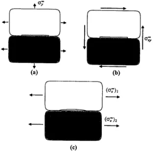
In this section we use the results obtained in the regular case, perturbed holes with cusps, to demonstrate a practical application. In general, the roughness of bimaterial interface is usually examined with the schemes as shown in Fig. 5a or sometimes Fig. 5b, regardless of the unevenness of the interface crack. With some experimental approaches the critical values of the stress intensity factors can be determined and used to be referred in many practical purposes. From Eq. (5.21) the critical values Kl,cr i and gli,cri Can be found with respect to the maximum opening stress (try)M and shear stress (O-x~)M.
For the opening test in Fig. 5a, the critical values Kl,cr i and KH,cr i are presented as
Ki,cr i =
~['-~A(o'7) M
and (7.1)196 C.-H. Chen, J. Hsu / Mechanics of Materials 24 (1996) 175-198
For the shear test in Fig. 5b, the critical values K~.cr ~ and Kn.c~ i are presented as
K l,cr i = ~ B (O'xy) M and A
Kll.cri = ~-'~ (O'xY)M.
(7.3) (7.4) The constants A and B appearing in Eqs. (7.1), (7.2), (7.3) and (7.4) are
a = cos( a In 2) + 2 a sin( a In 2 and B = sin( a In 2) - 2 a cos( a In 2).
And the interesting perturbed-interface problem concerned in this paper has its configuration as shown in Fig. 5c. Without considering the higher order terms, the critical values K l . c r i and Kll,cri induced by the lateral stress can be derived from Eq. (5.25).
Kl.cri = el/'-~ [ 4 a ( 1 + ~ ) 1 - y - 2 y * . . .
(ae~-B) (o~)IM
] ~ and (7.5)[ 4 c ~ ( 1 + 6 ) - - B a ) ] ( o - x ) , M .
Kn.cri = _~gr-~ {--- Y---2~* ( A ~ (7.6)
Compare Eq. (7.5) with Eq. (7.1), when the critical value K l , c r i is approached, the required lateral stress can be computed by the opening stress which has been determined from the test scheme in Fig. 5a.
[ 4o,1+ ,
]
(O'?) l M ~- ~ { ~ ~ " ~ ,
( A a - B )
A(O'y)M
(7.7)In contrast to Eq. (7.7), if the critical value Ku,cr i is approached, then from Eqs. (7.6) and (7.2) the required lateral stress will be
[
4ol(1+8)
- B c ~ ) B(~rT)
]
M
(7.8)( Ox),M = ~ . . . ( a 1 - - y - - 2 y *
The same method can also be used to determine the required lateral stress when the critical values of the stress intensity factors are obtained from the shear test scheme in Fig. 5b.
8. Conclusions
The purpose of interfacial fracture mechanics is to define a measurable and usable material property, toughness, to quantify fracture resistance of interfaces. The basic notions of interfacial fracture mechanics are summarized in Rice (1988). The theory is always used to analyze a fiat thin-cut of semi-infinite or finite length in interface of bimaterial. Here we try to extend the theory to include perturbed-interface cracks. Due to the agreement with reality, the concept of interface fracture mechanics now involves treating a crack with smoothly perturbed surfaces. The basic techniques for this purpose are Muskhelishvili's potential formulation and perturbation analysis that have been demonstrated in this present paper with selected examples. The perturbed- interface cracks are categorized regular and singular types by their different local geometries around the tips. Regular perturbation procedure provides the solution to the regularly perturbed-interface cracks. Boundary layer theory, however, is used to solve the singularly perturbed-interface cracks. First order solution for stress intensity factors at tips of regular examples, hole with cusps and smoothly undulating-interface crack, have been presented. The dominating effect in the first order term is the summation of coefficients of homogeneous polynomial solution multiplied by
X(z)
of complex function ~ l ( z ) . This result comes from the fact that Y~_ (___ 1) = -Y'_ ( + 1) = 0. The singular character at tip obtained from X'(z) is the same as the one determinedC.-H. Chen, J. Hsu / Mechonics o f Materials 24 (1996) 175-198 197
for the conventional thin-cut interface crack of bimaterial because they have the same local geometry around the tip. That is the reason why the regularly perturbed-interface cracks are so defined. A simple substitution shows that the summation of coefficients of the homogeneous solution involves the longitudinal load crx ~ , although Y'_+(___ 1) = 0 in regular examples. Outer solution to the singular examples is determined by following the same method used to solve the regular ones because the surfaces of singularly perturbed-interface cracks are so defined that their derivatives at x = ___ 1 can not vanish simultaneously. The singularity at tip is not only provided by X'(z) but also by the other terms existing in the complex functions ~'1(z) and ~ ; ( z ) . The singular characters at tip, except the one derived from X'(z), are not reasonable such that the outer solution is not valid in the extreme vicinity of tips. For this reason, inner solution is then constructed for satisfying the local singularity. A general expression of inner solution for different small notch-tips was derived from the conventional Williams' asymptotic expansions. This expression needs to be matched by the outer solution for determining the unknown coefficients. The matched asymptotic expansions, however, represent the local behaviour of notch-tip structure of bimaterial.
c¢
There are some interface-fracture mechanisms of composites under the ignorable Cry and crxy and the crucial or f, such as in the interfaces between thin-film and substrate or fiber and matrix. This type of fracture phenomena is very critical in many practical problems. When the lateral stress crf is much greater than other stresses cry and cry, the zero-th order solution with only Crfl and Cr~ can be ignored and the first order solution is then notable because it still retains the dominating stress off. In this type of interface fractures, the unevenness of the crack faces is the reason to introduce the lateral stresses into the stress intensity factors. If the crack is assumed to be a fiat thin-cut in its study, then the lateral stresses will not be taken into account for the fracture behavior and gives zero stress intensity factors, due to the vanishing Cry and crxy. Obviously, it can not be solved under the simplified thin-cut assumption. In this paper, we have presented several explicit results derived for this mechanism by considering the unevenness of the interface crack, those solutions give the insight of the effects induced by the lateral stress in composites.
Acknowledgements
This work was supported by the National Science Council, R.O.C., under grant NSC-85-2216-E-002-009.
References
Bogy, D.B. (1968), Edge-bonded dissimilar orthogonal elastic wedges under normal and shear loading. ASME J. AppL Mech., 460-466. Bogy, D.B. (1971), Two edge-bonded elastic wedges of different materials and wedge angles under surface tractions. ASME J. Appl. Mech.,
377-386.
Chen, C.H. and J. Hsu (1995), The stress intensity factors of slightly undulating interface cracks of bimaterials, Int. J. Fract., accepted for publication.
Cherepanov, G.P. (1979), Mechanics o f Brittle Materials, McGraw-Hill, New York.
Cole, J.D. (1968), Perturbation methods in applied mathematics, Blaisdell Publishing Company. Cotterell, B. and J.R. Rice (1980), Slightly curved or kinked cracks, Int. J. Fract. 16, 155-169.
Dundurs, J. (1969), Discussion of Edge-bonded dissimilar orthogonal elastic wedges under normal and shear loading, ASME J. Appl. Mech. 36, 650-652.
England, A.H. (1965), A crack between dissimilar media, ASME J. Appl. Mech., 400-402. England, A.H. (1971), Complex Variable Methods in Elasticity, Wiley-Interscience.
Gautesen, A.K. and J. Dundurs (1987), The interface crack in a tension field, ASME J. Appl. Mech. 54, 93-98. Goldstein, R.V. and R.L. Salganik (1974), Brittle fracture of solids with arbitrary cracks, Int. J. Fract. 10, 507-523. Hein, V.L. and F. Erdogan (1971), Stress Singularities in a Two-Material Wedge, Inter. Frac. Mech. 7(3), 317-330.
Karihaloo, B.L., L.M. Keer, S. Nemat-Nasser and A. Oranramachai (1981), Approximations to slight crack kinking and curving, ASME J.
Appl. Mech., 515-519.
198 C.-H. Chen, J. Hsu / Mechanics o f Materials 24 (1996) 175-198
Muskhelishvili, N.I. (1953), Some basic problems o f the mathematical theory o f elasticity, transl. J.R.M. Redok, Noordhoff.
Movchan, A.B., N.F. Morozov and S.A. Nazarov (1987), Cracks with smoothly closing edges under plane deformation, PMM 51(N1)~ 130-139.
Rice, J.R. (1988), Elastic fracture mechanics concepts for interracial cracks, ASME J. Appl. Mech. 55, 98-103. Rice, J.R. and G.C. Sih (1965), Plane problems of cracks in dissimilar media, ASME J. Appl. Mech. 32, 418-423. Sih, G.C. and J.R. Rice (1964), The bending of plates of dissimilar materials with cracks, J. Appl. Mech. 31,477-482. Sumi, Y., S. Nemat-Nasser and L.M. Keer (1983), On crack branching and curving in a f'mite body, Int. J. Fract. 21, 67-79. Sumi, Y., S. Nemat-Nasser and L.M. Keer (1985), On crack path stability in a finite body, Eng. Frac. Mech. 17, 759-771. Williams, M.L. (1959), The stresses around a fault or crack in dissimilar media, Bull. Seismol. Soc. Am. 49, 199-204. Wu, C.H. (1994), Regularly and singularly perturbed cracks, Q. Appl. Math. 52(3), 529-543.