A GUI Simulation Model in Supporting Embedded Software Design
Wei-Chung Hu
Ming-Lun Lee
Tzung-Shian Tsai
Hewijin Christine Jiau
Institute of Computer and Communication Engineering,
National Cheng Kung University, Taiwan, R.O.C.
{selain,living,apfols}@nature.ee.ncku.edu.tw,
[email protected]
Abstract
The goal of embedded systems is to embed services into our daily life in a convenient and comfortable manner without intrusions. The graphical user interfaces (GUIs) of embedded softwares play an important role in reaching this goal. However, the rapid growth of various types of embedded devices and platforms, especially mobile devices, brings more challenges and constraints for GUI design in embedded software. Current approaches in building conventional software GUI result in iterative refinement after it was built, which is not acceptable for embedded software. In this study, a GUI simulation model is proposed to assist embedded software developers to generate GUI prototypes in early phase. The generated prototype can be used to confirm the usability requirement of customers and eliminate the further need of iterative GUI refinement. The simulation is based on evolutionary simulation rules which evolve according to the training data and design experience from existing popular GUI designs, which implies high adaptability and flexibility to the changing world with newly released embedded devices. Keywords: GUI Simulation, Reflexion Model, GUI Design, Embedded Software Design, Prototype Genera-tion.
1
Introduction
Graphical User Interfaces (GUIs) have become an im-portant and must-have way for user to interact with today’s softwares. The purpose of providing GUI is to bridge the gap between user’s conceptual model and developer’s pro-gramming model [1, 2]. The optimal goal of GUI is to provide the user an intuitive operating interface without a long learning process. Considering the goal of embedded
systems is to embed services into human life in a comfort-able manner without intrusion [3], the issues of GUI design in embedded software are especially important.
There were already tools [4, 5] and environment [6] pro-posed to help GUI design. However, even with the help of GUI development theories, guidelines and tools, there still exist mismatch parts between resulting GUI, which developers build, and the expecting GUI, that customers and developers desire. The design and implementation of GUI will be effected by many constraints from different sources, such as current developers, developers of simi-lar software, developers’ knowledge on GUI design, hard-ware constraints, materials and tools used to implement the GUI [7, 8]. In some cases the mismatch is not acceptable for developers or customers, and the developers need to refine or redesign the GUI iteratively. However, according to the specific goal of embedded systems, the redesign of GUI in embedded software is usually not acceptable be-cause customers are required to pay extra effort to adapt themselves to the redesigned GUI. Further more, under the global vision of ubiquitous computing environment, more and more interactive embedded devices and mobile devices are newly built and released. A single software applica-tion will have several GUIs on variety of devices [9–11]. Each devices may also contributes his own hardware oper-ating constraints to the GUI design of embedded software. Therefore, how to understand the usability requirement of customers in early phase in order to eliminate the need of refinement iteration, and how to avoid the redesign the GUI under the consideration of variety of devices, are critical issues for GUI design in embedded software.
In order to solve these issues, a GUI simulation model is proposed in this study to support embedded software GUI design. The proposed simulation model equips with two capabilities. The first one is to generate GUI proto-types for gathering usability requirement from customers in early phase, and the other one is to utilize the experience
of how other developers deal with constraints as guidelines for designing new embedded softwares. For embedded software GUI design, the proposed simulation model plays the role as an “adviser”. An adviser is who not only an expert of a specific domain, but with fully experience to provide advice. The simulation model accumulates GUI design knowledge from well-designed embedded software, and keep these knowledge as simulation rules. While de-veloping a new embedded software, the simulation model apply these knowledge to guide and complement the de-sign of embedded software GUI, just as an adviser will do. The proposed simulation model encapsulates the de-cision making processes as simulation rules. The dede-cision making process starts from considering the constraints, and finalizes in the design of GUI. With the simulation rules, this work can simulate the process of how developers con-sider the constraints and how they design GUI under these constraints.
Puerta [12] defines four attributes as being nature to user interface tools: process orientation, interoperability, localized functionality, and designer impact. The proposed simulation model fulfills three of them :
1. Process Orientation: Because the simulation model
takes scenarios as input, and the GUI prototype as output, it can easily conform to popular software de-velopment process.
2. Interoperability: The simulation model lets the
devel-opers be able to compare the simulated GUI model with GUI model designed by using other tools, and to complement each other.
3. Designer Impact: Since the simulation model
accumu-lates other designers’ knowledge on considering fac-tors and designing GUI, the simulation process itself is extremely helpful for developer who lack the knowl-edge, skills, or experience required for optimal GUI design.
The impact of applying proposed simulation model in em-bedded software development project can be viewed from three aspects. First, this simulation model reduces design complexity from possible design variations. By considering the design constraints from scenarios, and understanding customer’s usability requirements in early phase, the poten-tial design complexity from design variations can be greatly reduced. By reduction of design complexity, the possible design variations can be well-planned, and the chance of redesign can be lowered down. Second, the model-based approach provides suitable abstraction for GUI develop-ment. The result of simulated GUI model is an abstract model for final implementation. An abstract model can help developers focus on relevant aspects and avoid deal-ing with low-level details [9]. The abstraction makes it
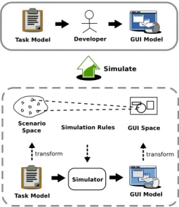
Figure 1. GUI Simulation Concept Diagram
easier to adapt the simulated model into various types of embedded devices. Third, the proposed simulation model promotes software reuse crossing projects. The reusable artifacts as simulation rules are the knowledge of how de-velopers considering their GUI design. With the utilization of proposed simulation model, the newly developed em-bedded software’s quality is also improved in usability and maintainability.
2
Simulation Model
The overall concept of proposed simulation model is shown in Figure 1. Before simulation, the modeling ap-proach of input and simulation result needs to be defined first. The Design Space [13, 14] concept is applied to build the simulation model.
2.1
Scenario Space and Factor Modeling
The requirement scenario is chosen as a modeling unit. The reason of choosing requirement scenario is because scenario-driven approach [15] is a popular software re-quirement analysis approach. Also, the scenario-driven approach is used in supporting software GUI design [1]. A scenario is modeled as a Scenario Space. The GUI Design
Factors are defined as dimensions of scenario spaces. A
GUI design factor is a factor that GUI designer will take into consideration when he builds the GUI from scenarios. The GUI design factors form the dimensions of the scenario spaces. According to [14], the GUI design factors are cat-egorized into two groups including external requirements and basic interactive behavior.
External Requirements Group:
• User interaction type is a dimension indicating the user’s attitude toward the task.
• Frequency of task is a dimension indicating the fre-quency of the task the user performs during the lifetime of the application.
• Importance of task is a dimension indicating the im-portance of the task in the application.
• User type is a dimension indicating the kind of user will perform the task.
• Number of decision making to complete the task is a dimension indicating how many times of decisions the user has to make to complete the work.
Basic Interactive Behavior Group:
• User action type is a dimension indicating the kind of action the user might perform.
• Input data volume is the dimension indicating the total input data volume when performing the task. • Output information type is the dimension indicating
the type of information the system reports.
• Output data volume is the dimension which indicates output data volume when performing the task. • Time to complete a single task is the dimension which
indicates how long does it take for the system to com-plete the task.
• Number of entities involved in a scenario is a di-mension indicating total number of nouns mentioned in the scenario description, but the repetitive ones are excluded.
2.2
GUI Space and Characteristic Modeling
As for software GUI modeling, part of the GUI elements, such as buttons, selection menu, text areas or images, which realize one of the scenarios, are chosen to form the GUI
Space. The GUI Characteristics are defined as
dimen-sions of GUI space. The GUI characteristics of GUI shows the features from user perspective, such as what GUI looks like, what entities on it and GUI usability. Previous re-searches have been done a lot in GUI modeling [5, 14, 16]. Referring to these researches, the characteristics are classi-fied into two groups: control flow and representation issues, and corresponding dimensions are listed. The control flow group considers the dynamic behavior of GUI expression. The representation issue group considers the user interface layout of GUI entities and data.
Control Flow Group:
• Action Type: This states the interaction type of tasks in GUI space, such as function selected or button pressed by user to enforce task is Single Selection.
Input and Trigger are the type that user enters some
data and presses button to execute. The type will pop on new windows for other sequence of actions is kind of Sequence External Handle.
• Scenario Start Point: Scenario start point is the exact GUI element where the task scenario starts. Generally, the Menu Bar will contain all functional tasks. • Sub-Space Size: The number of sub-spaces which the
task scenario has.
• Action Depth: This describes the “length” of action to complete a task scenario. For example, the menu item is pressed to open a file chooser. After the target file is selected, the file is opened in viewer window. The total depth is 2, from menu to file chooser. • Input Device: This describes the input device of the
task, such as mouse or keyboard.
Representation Group:
• Number of Entities: The number of GUI entities related to the task scenario.
• Area Size: The summation of GUI entities areas re-lating to current task scenario.
• Action Start Position: The position in the top GUI panel that can tiger the action.
• User Help Guide: This characters the help or guide statements of task scenario process.
• Entities Customizable: This characteristic states if the GUI entities are customizable. Different cus-tomization styles may occur, such as size customiza-tion, location customization.
• Output Information Visualization: The visualiza-tion style of output informavisualiza-tion.
2.3
Simulation Rule and Its Training
The simulation model defined in Section 2 is used to simulate the GUI model. The input of the simulator will be the scenario spaces with GUI design factors, and the output will be GUI spaces with GUI characteristics. Simulation Rules are defined as a pair constituted with a set of GUI design factors and a set of GUI characteristics, as shown in Figure 1.
The simulation rules may be predefined in two ways. The first one is directly predefined. Domain Trainer (Fig-ure 2) can set the predefined simulation rules as hypothesis.
Figure 2. Training Phase Process
In the second way, the domain trainer can extract factor-characteristics datasets from training materials, and use the data mining technique, such as association rules technique, to gain the predefined rules. The predefined rules gained from both ways are needed to be trained in trained phase, and well predefined rules save the total training time.
The contents of GUI design factors, GUI characteristics and the simulation rules are domain-relevant, which means the simulation rules may vary in different application do-mains even the constitution factors and characteristics are the same. Thus the construction of simulation rules de-pends on training with data collected from one or multiple softwares from specific domains.
In the training phase, domain trainer collects popular softwares as materials. The popular softwares are usually with great GUI design principles. The domain trainer models the factors of popular softwares to generate simu-lated GUI model, and refine simulation rules iteratively to make the simulated model close to the existing GUI model. Some tools, such as genetic algorithm, neural network or data mining methods, are utilized to help build up the sim-ulation rules between the scenario space model and GUI space model.
After the training complete, the simulation rules reflect the thought of other GUI designers doing GUI design in specified application domains. And the GUI simulation itself is the process to re-apply these thoughts in building new software in similar application domains.
3
Simulation Process
The simulation process is a two-phase process. The first phase is Training Phase, and the second one is Simulation
Phase. The detail steps of these two processes will be
described in following sections.
3.1
Training Phase Process
The purpose of training phase (Figure 2) is to construct the simulation rules in current application domain. The simulation rules are mostly domain-relevant rules, and they need to be trained to be adapted to current domain. The rules may be predefined by domain trainer, but in order to gain better guidance in a specific domain, they need to be trained with existing softwares from other similar domains. The refinement of simulation rules depends on the mismatch between simulation result and existing softwares. The con-cept of Software Reflexion Model [17] is utilized in this work to infer the difference between existing GUI model and simulated GUI model, and then providing evidence and guidance for domain trainer to refine the simulation rules semi-automatically. The steps of training phase process are described as following:
Step 1: The Domain Trainer needs to prepare some popular
softwares with GUI as training material.
Step 2: The domain trainer generates some speculated
sce-narios according to a specific existing software, then assigning factors on each speculated scenario with the help of Scenario Space Constructor to form
Specu-lated Scenario Spaces with Factors.
Step 3: The speculated scenario spaces with factors will
be send into Simulator and resulting Simulated GUI
Step 4: The specific existing software is input for
extrac-tion tools, and the extracextrac-tion tool automatically gener-ates Existing GUI Model.
Step 5: The simulated GUI model and the existing GUI
model will be compared by GUI Reflexion Model
tools (GRM tools), and result in GUI Reflexion Model (GRM).
Step 6: Domain trainer observes the GRM, and then
de-cides how to tune the simulation rules with the help of
Simulation Rule Tuner.
The process may repeat more than once until domain trainer has confidence with the simulation result, which means the mismatch between two models is acceptable and the simulation rules are close to the original developer’s thought on the GUI design of the specific software.
3.2
Simulation Phase Process
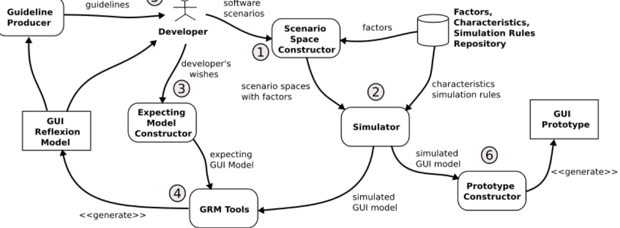
In the simulation phase (Figure 3) , the trained simula-tion rules are used to simulate GUI design from software scenarios. The simulation rules are applied to perform sim-ulation. The developer can provide the expecting model based on his own desires, experience and knowledge, and again, use the GRM tools to compare the expecting model and the simulated model. Detail steps are described as folowing:
Step 1: Developer constructs scenario spaces with the help
of Scenario Space Constructor.
Step 2: The scenario spaces with factors are input into
simulator, and the simulator requires simulation rules from database based on factors input. The Simulator then simulated the GUI model.
Step 3: The developer may want to construct expecting
GUI design model with his won wishes.
Step 4: The GUI reflexion tool compares the simulated
GUI model and expecting GUI model, and generates GRM for the developer.
Step 5: With the help of Guideline Producer, developer can
easily refine his design by referencing the GRM and guidelines.
Step 6: The simulated GUI model can be used to generate
GUI prototype.
The simulation phase may go more than one iteration, until the developer has confidence in the simulation result and the GRM.
4
Related Work
4.1
GUI Design for Embedded Software and
Mo-bile Devices
The importance of GUI design for embedded soft-ware and mobile devices has been noticed by researchers. Bishop [11] addressed the issue of how the user interface can be successfully engineered for portability across mul-tiple platforms and on mulmul-tiple devices. The discussed solutions are all around the use of XML-based technolo-gies and methodolotechnolo-gies. Subramanya et al. [8] discussed several limitation and constraints of designing user inter-faces for mobile content. Also they list several goals for user interface design. Yang et al. [18] introduced a new mini visual IDE, called VY, which supports rapid develop-ment utilizing control library, and simulation of GUI. Their simulation focus on running embedded GUI software on simulated hardware, which is different form simulation in our study. Braun et al. [19] explored building interfaces for federations of personal mobile and stationary embed-ded devices. Their approach is mainly a fission process which takes context information from both user and ap-plication to produce a suitable concrete user interface. In the work of Butter et al. [20], an XUL-based user interface framework was developed to ease the development burden caused by heterogenous mobile devices and context of the user. The adoption of XUL benefits in separating the user interface adaption from the application logic. The user context awareness is also an important issue in Repo et al’s work [21]. In the review of these works, three impor-tant issues are found. First, the context awareness issue is critical for GUI in mobile devices, which means designed embedded software GUI must has the adaptability and flex-ibility to deal with the changing context. Second, suitable abstraction and model-based approach is the key for adapt-ing GUI on multiple embedded devices. For the last one, currently XML-based technologies are widely used to sep-arate the implementation details from design. Even more, middleware-based approaches can be the powerful solution for design/implementation separation.
4.2
GUI Prototyping
GUI prototypes offer designers and customers a form of representation for specification and an exploration approach for visual design ideas. In proposed simulation model for GUI design, the developer needs to specify a expecting GUI model and simulate a simulated GUI model, and then gen-erate GUI prototype after being satisfied with the result of simulation. An abstract prototype is used in content mod-eling [22], which represents the contents of user interfaces and their various constituent sections independent from de-tails of appearance and behavior. They use predefined key
Figure 3. Simulation Phase Process
notation elements to describe the contents and action types of a GUI layout. Some researches try to model GUI with UML description and develop an GUI layout tool for ex-pressing the meaning of UML by symbolic element [23], which is very interesting to show the prototypes of GUI in a friendly way.
Recently, the scenarios in software development have gain attention in human computer interaction analysis [24]. As the popularity of employing use cases to formally rep-resent scenarios in object-oriented software development, recent researches have focused on the use case based ap-proaches for GUI prototype generation [25–29]. An use case usually contains step by step interactions and message exchange between the user and the application. The or-dering and complexity of interactions, and the exchanged messages are critical information for GUI design. More-over, several models, such as object and association model, sequence model, activity model, collaborative model, or Petri-Net model, can be derived semi-automatically from use cases. These models can provide further information for GUI prototype generation.
4.3
GUI Design Modeling
The proposed simulation model involves the concept of design space to simulate the GUI model for developer at early phase. Design space can be used in feature model-ing [30] that expresses the dimensions of features in the domain. The correlations can be specified between fea-tures which are highly relevant. This is similar to what is observed in this study, but it only describes the relation-ships at the same domain. In this study, the relationrelation-ships between the factors of requirement domain and characteris-tics of GUI expression domain are discovered. In [14, 31], they use design space for modeling user interface archi-tecture. What their concerns are functional dimensions of
GUI, structural dimensions of GUI, and the rules from func-tional space to structure space. Although utilizing the same design space concept, this study focuses the requirements from use case scenarios and GUI prototype expression.
The detail of the GUI is not the issues which are needed to be concerned at the beginning of the GUI design. For this reason, most GUI modeling methodologies would show the abstract view rather than detail of GUI. In [16], the author proposes a content model in terms of a collection of mate-rials, tool, and working space to bridge the conceptual gap between a task model and a representational paper proto-type for a user interface design. Materials are the stuff that users are interested in. Tools enable users to do things with materials, and working spaces are the various parts of the user interface that combine the tools and materials together into useful collections. Some researchers [32, 33] observe the nesting structure of GUI can be modeled by extending the UML diagrams and elements, especially in the web ap-plication. These approaches are derived for the utilization of some task models, such as use case, as the concern to starting the GUI design.
User interface design within the Rational Unified Pro-cess(RUP) involves user interface modeling and user inter-face prototyping [34]. The extended tabular use case and UI element clusters are used to provide a bridge between user interface modeling and user interface prototyping ac-tivities. However the extended tabular use case can only express the GUI clustering of functions without design con-sideration dimensions. The simulation model proposed in this study starts from the use case specification and maps the design considerations from requirements to the simulation model of GUI, and then generate the GUI prototypes.
5
Conclusion
This study provides a GUI simulation model to sup-port embedded software design in understanding usability requirements from customers and adapting to multiple de-vices. The simulation model takes scenarios as inputs, and results GUI design guidelines or GUI prototype. With the training process and simulation process, the GUI prototype can be refined rapidly and better reach the ideal interface of customers. Also, with the extraction and inclusion of de-sign knowledge from well-dede-signed embedded softwares, the generated prototype can be a useful evolutionary model for adapting built GUI into variety of devices. Such a model is process-oriented, with interoperability, and be able to help designer who lacks the GUI design knowledge. The proposed simulation model is also easy to be integrated into current popular development process, such as RUP.
References
[1] D. Collins, Designing Object-Oriented User Inter-faces. Addison-Wesley, 1995.
[2] T. Mandel, The Elements of User Interface Design. John Wiley & Sons, 1997.
[3] N. Streitz and P. Nixon, “The Disappearing Com-puter,” Communications of the ACM, vol. 48, no. 3, pp. 32–35, March 2005.
[4] D. B¨aumer, W. R. Bischofberger, H. Lichter, and H. Z¨ullighoven, “User Interface Prototyping - Con-cepts, Tools, and Experience,” Proceedings of the 18th International Conference on Software Engineering, pp. 532–541, March 1996.
[5] J. Shirogane and Y. Fukazawa, “Method of User-Customizable GUI Generation and Its Evaluation,” Proceedings of the 5th Asia Pacific Software Engi-neering Conference, pp. 377–384, 1998.
[6] B. A. Myers, R. G. McDaniel, R. C. Miller, A. S. Ferrency, A. Faulring, B. D. Kyle, A. Mickish, A. Klimovitski, and P. Doane, “The Amulet Envi-ronment: New Models for Effective User Interface Software Development,” IEEE Transactions on Soft-ware Engineering, vol. 23, no. 6, pp. 347–365, June 1997.
[7] J. T. Hackos and J. C. Redish, User and Task Analysis for Interface Design. John Wiley & Sons, 1998. [8] S. Subramanya and B. K. Yi, “User Interfaces for
Mo-bile Content,” IEEE Computer, vol. 39, no. 4, pp. 85– 87, May 2006.
[9] G. Mori, F. Patern ´o, and C. Santoro, “Design and Development of Multidevice User Interfaces through Multiple Logical Descriptions,” IEEE Transactions on Software Engineering, vol. 30, no. 8, pp. 507–520, August 2004.
[10] S. Berti, F. Patern ´o, and C. Santoro, “Natural Devel-opment of Ubiquitous Interfaces,” Communications of the ACM, vol. 47, no. 9, pp. 63–64, September 2004. [11] J. Bishop, “Multi-Platform User Interface
Construc-tion: A Challenge for Software Engineering-In-The-Small,” Proceeding of the 28th International Confer-ence on Software Engineering, pp. 751–760, 2006. [12] A. Puerta, “A Better Future for UI Tools through
En-gineering,” ACM CHI Workshop, April 2005. [13] T. G. Lane, Guidance for User Interface Architecture,
in Software Architecture: Perspectives on an Emerg-ing Discipline. Prentice Hall, 1996.
[14] T. G. Lane, Studying Software Architecture Through Design Spaces and Rules. Technical Report CMU/SEI-90-TR-18, Carnegie Mellon Univ., 1990. [15] I. Sommerville, Software Engineering.
Addison-Wesley, 2004.
[16] L. L. Constantine, “Rapid Abstract Prototyping,” Soft-ware Development, vol. 6, no. 11, November 1998. [17] G. C. Murphy, D. Notkin, and K. Sullivan, “Software
Reflexion Models: Bridging the Gap between Design and Implementation,” IEEE Transactions on Software Engineering, vol. 27, no. 4, pp. 364–380, April 2001. [18] L. Yang, Y. Choi, C. Seo, T. Yang, and M. Kim, “De-sign of VY: A Mini Visual IDE for the Development of GUI in Embedded Devices,” Proceedings of 5th ACIS International Conference on Software Engineer-ing Research, Management & Applications, pp. 625– 632, 2007.
[19] E. Braun and M. M´’uhlh´’auser, “Automatically Gen-erating User Interfaces for Device Federations,” Sev-enth IEEE International Symposium on Multimedia, 2005.
[20] T. Butter, M. Aleksy, P. Bostan, and M. Schader, “Context-Aware User Interface Framework for Mo-bile Applications,” 27th International Conference on Distributed Computing Systems Workshops, 2007. [21] P. Repo and J. Riekki, “Middleware Support for
Im-plementing Context-Aware Multimodal User Inter-faces,” Proceedings of the 3rd International Confer-ence on Mobile and Ubiquitous Multimedia, pp. 221– 227, 2004.
[22] L. L. Constantine, “Canonical Abstract Prototypes for Abstract Visual and Interaction Design,” 10th Inter-national Workshop on Design, Specification and Veri-fication of Inter-active Systems, LNCS - Lecture Notes in Computer Science, 2003.
[23] K. Blankenhorn, A UML Profile for GUI Layout. Mas-ter Thesis, Department of Digital Media at University of Applied Sciences Furtwangen, May 2004. [24] B. A. Nardi, “The Use of Scenarios in Design,” ACM
SIGCHI Bulletin, vol. 24, no. 4, pp. 13–14, October 1992.
[25] L. L. Constantine, “Essential modeling: Use Cases for User Interfaces,” ACM Interactions, vol. 2, no. 2, pp. 34–46, April 1995.
[26] L. L. Constantine and L. A. D. Lockwood, “Structure and Style in Use Cases for User Interface Design,” Ob-ject Modeling and User Interface Design: Designing Interactive Systems, pp. 245–279, 2001.
[27] S.-K. Kim and D. A. Carrington, “Integrating use-case analysis and task analysis for interactive systems,” Proceedings of the Asia-Pacific Software Engineering Conference, pp. 12–21, 2002.
[28] J. M. Almendros-Jim´enez and L. Iribarne, “Designing gui components for uml use cases,” Proceedings of the IEEE International Conference and Workshops on the Engineering of Computer-based Systems, pp. 210– 217, 2005.
[29] M. Elkoutbi, I. Khriss, and R. K. Keller, “Automated Prototyping of User Interfaces based on UML Sce-narios,” Journal of Automated Software Engineering, vol. 13, no. 1, pp. 5–40, January 2006.
[30] L. Geyer, “Feature Modeling Using Design Spaces,” 1st German Workshop on Product Line Software En-gineering, pp. 35–42, November 2000.
[31] T. G. Lane, A Design Space and Design Rules for User Interface Software Architecture. Technical Report CMU/SEI-90-TR-18, Carnegie Mellon Univ., 1990. [32] K. Blankenhorn and W. Walter, “Extending UML to
GUI Modeling,” Mensch & Computer, pp. 307–308, 2004.
[33] R. Hennicker and N. Koch, “Modeling the User In-terface of Web Applications with UML,” UML 2001, LNI 7, pp. 158–172, 2001.
[34] C. Phillips and E. Kemp, “In Support of User Inter-face Design in the Rational Unified Process,” Third Australasian User Interface Conference, 2002.