A New Approach for Serving Radio Network
Controller Relocation
in
UMTS
All-IP Network
Ai-Chun
Pang'.
Yi-Biny Lint, Hsien-Ming Tsaitand I'rathirna
Ayrawals 'Dept. of Comp. Sci B Info. Engr.. National Taiwan UniversityTaipei, Taiwan, R.O.C.; Emaii: acpang~csie.ntu.edu.tw tC1iair Professor. Providence University
Taichung, Taiwan. R.O.C.: Email: liny@csie.nctu.edu.tw tQuanta Research Inst.. Quanta Computcr Inc. Taoyuan. Taiwan. R.O.C.: Eamil: samuel.tsai@quantatw.com $Internet Architecture Research Lab.. Telcordia Technologies Momstown, NJ 07960-64311: Emaii:pagrawal @research.telcordia.com
Abstract-To support real-time multimedia servires in UMTS all-IP network. 3GPP TR 25.936 proposed two approaches to support real-time Sen,ing Rndio Nenvork Conrmller (SRNC) switching, which require packet duplication during SRNC re-
location. These approaches significantly consunie extra system resources. This paper pmposes the Jbrr SRNC nlocnriori (FSR) approach that d w s not duplicate packets. In FSR, a packet buffering mechanism is iniplemented to avoid packet loss at the target RNC. We propose a n analytic model to investigate the perfurnlance of FSR. The numerical results show that packet 1 0 s
ut the source KNC can be ignored. Furthermore. the expected nuniher of packets huffered at the target RNC is sniall, which does not prolong packet delay.
I. INTRODUCTION
Mohility. privacy and immediacy offered by wireless access commonly create new npportunities for Internet business. and mobile networks are becoming
a
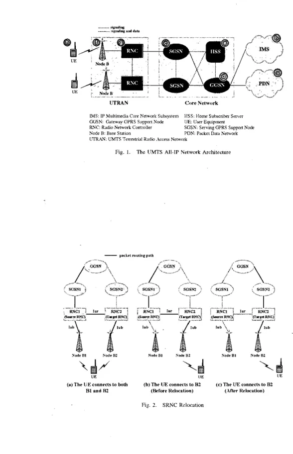
platform that provides leading-edge Internet services. Through integration of the Internet and the third generation (3G) wireless communication, next generation telccommunications networks will provide global information access for mobile users 1111. 3GPP [I]. [5], [6] proposed the Universal Mobile Telecoiiriiiimications S ~ S V S I P I I I (UMTS) all-IP architecture to integrate the IP and wireless technologies. which has cvolvcd from the GSM. General Packet Radio Semire (GPKS), and UMTS Release 1999.Figure I shows a UMTS all-IP network architecture (another
UMTS all-IP option can he found in [I]. [SI). In this figure. the dashed lines represent signaling links, and the solid lines represent data and signaling links. The IJMTS all-IP network connects to the Packer Data Netwui-k (PDN:
see
Figure 1 (a)) or the IP Mirlrimedia Core Nrrwork SiiDsysteiii (sec Fig- ure I (b)) through the Seming GPRS Si(pp#i-t Node (SGSN: see Figure 1 (c)) and the Garenav GPRS Siippon Node (GGSN; see Figure 1 (d)). The SGSN connects to the radio access network. The GGSN provides interworking with the external PDN. and is connected with SGSNs via an IP-based GPRSbackbone network. Both the GGSN and SGSN communicate with the Hoiiie SiiOscriOer S e n w (see Figure 1 (e)) to obtain mobility and session management information of subscribers. The UMTS Terrestrial Radio Acress Nemork (UTRAN) con- sists of Node Bs (the UMTS term for base stations; see Figure 1 (t)) and Radio Netum4- Controllers (RNCs:
see
Figure 1 (g)) connected by an A I M network. A iiser eqiiip- menr ( U E see Figure I (h)) cominunicates with one or more Node Bs through the radio interface Uic based on the wideband CDMA (WCDMA) radio technology [SI.In the UMTS all-IP ngtwork. the IP packets are routed between the UE and the GGSN. By using the Packet Dara Protocol (PDP) context activation procedure [41.
a
PDP con- text is created to estahlish the routing path for IP packet delivery. Besides the packet routing information (e.g.. the U E s IP address). the PDPcontext also contains the QoS profiles and other parameters. Due to the CDMA characteristics. multiple radio paths (for delivering the same 1P packets) may existbetween the UE and more than one Node Bs. An example of multiple routing paths is illustrated in Figure 2 (a). In this figure, an IP-based GPRS Tunneling Prolorol (GTP) connection is establishcd between the GGSN and KNCI. The IJE connects to two Node Bs ( B I and 8 2 ) . Node B1 is connected to RNCI. and Node B2 is connected to RNC?. An Iur link between RNCl and RNC? is esrablished so that the signal (i.e.. IP packets) sent from the UE to Node B2 can be forwarded to KNCl through RNCZ. RNCl then combines the signals from Node B l and B2, and forwards them to SGSNI. Similarly, the packets sent from the GGSN to RNCl will he forwarded to both Node B1 and RNC2 (and then NtAe B?). In this example. RNCl is called the Sen3ing RNC (SRNC). RNC? is called the Drqr RNC (DRNC), which transparently routes the packets through the lub (between the Node B and the RNC) and Iur (between two RNCs) interfaces. Suppose that the UE moves from Node B1 toward Node B?. and the radio link hetween the UE and Node B1 is disconnected. In this case. the routing path will he <UE-Node B?-.RNC?-RNCl -SGSNl-GGSN> as shown in Figure 2 (b).
- - ..
__
. . .. . .UTRAN Core Nelwork
M S : IP Multimedia Core Elefrork Subsystem WSN Gateway GPRS SupportPode
Node 8 : Base Station
LTR.&V: UMTS Tenesvlsl Radio . i c c c a Nelwoik
HSS: Honx Subrcrikr S n b e r U E User Equipment PDN: Packet Drlr Nelnaik RNC Ridio Network Coniroiler scss serving wns suppm NO&
Fig. 1. The UMTS All-IP Nztwort Archilcaure
t$/
....UE
\ $
I1EIn this scenario. it does not make sense to route packets
from the routing path. After SRNC relocation. the packets are Figure 2 (c)), and RNC? becomes the SRNC.
--- %"",%
hetween the UE and the core network through RNCl. There- fore SRNC relocation may be performed to remove RNCl
routed to the GGSN directly through KNC? and SGSN?
(see
Q
SGSN, ...
ei
mi
~SOUXC s u m
In 3GPP TS 23.060 [4].
a
lossless SRNC relocation pro- RNC RVC RNC RNC~ cedure was proposed for non-real-time data services. In this
t
J
' approach. in the beginning of SRNC relocation, the source
RNC (RNCI in Figure 2 (b)) first stops transmitting downlink
f
Ih) Slag* I1
d
< a , Sl2.eOI
IP packets to the UE. Then it forwards the next packets to the target RNC (RNC2 in Figure 2 (b)) via a GTP tunnel between the two RNCs. The target RNC stores all IP packets fonvarded from the source RNC. After taking over the SRNC role. the
In this approach. no packet is lost during the SRNC switching
period. Unfortunately, this approach does not support real-time data transmission because the IP data traffic will he suspended for a long time during SRNC switching. In order to support real-time multimedia services. 3GPP TR 25.936 [3] proposes SRNC drrplication (SD) and core neMWk bi-casting (CNB). These two approaches duplicate data packets during SRNC In this paper. we propose a new approach called fast SRNC
rrlocarion (FSR) to provide real-time SRNC switching without
packet duplication.
target RNC restaRs the downlink data transmission to the UE.
relocation, which may not efficiently utilize system resources. , < I stage 111 Id, Stage IV Fig. 1. The SRNC Duplication (SDI Approach
11. RELATED W O R K
This section describes the previously proposed SRNC re- location procedures Sor real-time multimedia services; that is, SRNC driplicution (SDI and core nehcork bi-casting (CNB) proposed in 3GPP TU 25.936 [31.
A. SRNC Dicplicafion (SO)
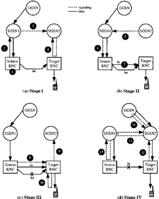
Consider Figure 2 (h). Suppose that the UE is connected to the source RNC and SGSNl before performing SRNC reloca- tion. Thc target RNC is the drift RNC, which is connected to the source RNC via the Iur interface. After SRNC relocation. the SRNC role is moved from the source RNC to the target RNC. and the IP packets for the U E arc directly routed through SGSN2 and the target RNC (see Figure 2 (c)). Figure 3 shows the four stages of the SD procedure. Stage I (Figure 3 (a))
initiates SRNC relocation. In this stage. the user IP packets
are
delivered through the old path <GGSN-SGSNlisource RNC-target RNC-UE>. The following steps are executed.When the Node B
of
the source RNC no longer connects to the UE, the source RNC initiates SRNC relocation. Specifically, the source RNC sends aRelocation-Required message (including the ID of the target RNC) to SGSNl .
1-2.
3. Based on the ID of the target RNC. SGSNl deter- mines if the SRNC relocation is intra-SGSN SRNC relocation or inter-SGSN SRNC relocation. Assume that it is inter-SGSN SRNC relocation. By sending a Forwarc.Relocation.Request messagc, SGSNl requests SGSN? to allocate the resources (to be described in Stcp 4) for the UB.
SGSN? sends a Relocation.Request message with
the Radio Accrss Bearer (RAB) parameters to the
target RNC. The RAB parameters include the mafic class (e.g.. conversational. streaming. interactive or background). trallic handling priority. maximum and guaranteed hit rates. and
so
on I?].
After all nec- essary resources for the RAB are successfully allo- cated. the target RNC sends a Relocation-Request- Acknowledge message to SGSN2.4.
In Stage II (Figure 3 (b)). a forwarding path <source RNC-target RNC-UE> for downlink packet delivery is created between the source and the target RNCs through the Iu interface. The source RNC duplicates the packets and forwards these packet.? to lhc target RNC. Thus the downlink packets are simultaneously transmitted through huth the old path (via the Iur interface) and the forwarding path (via the Iu interface) hetween the source RNC and the target RNC. Note that 3G TR25.936 [31 did not clearly describe if an Iu link can be directly established between two RNCs. If not. an indirect path <source RNC-SGSNI-SGSN2-target RNC> is required.
TI)
the favor source the and SD target approach.
RNCs.
we The assume following a direct steps link. are executed betweenf))
-,la* ---"%"dm%f)
e...:..,
in Stage 11.
SOSNZ
SFSE, ... SCPVI ---.-.-- SGSNI
5-6. SGSN? sends a Forward-Relocation
Response
sources (e.g.. RAB ) are allocated. SGSNl forwardsmessage to SGSNI. which indicates that all re-
81
oi
I
e /
this information to the source RNC through a Relo- RNC RhC RNC nvc
cation-Command
message. ur I",sage. the source RNC duplicates the downlink pack-
L,
Source T q r l suuric Tarsel
7. Upnn receipt of the Relocation.Command mes- ets and transmits the duplicated packets to the tar- get RNC through the forwarding palh (via the lu interface at the
IF
layer). The forwarded packets are discarded at the target RNC before it hecomes the SRNC (i.e.. before the target RNC receives theRelocation.Commit
message at Step 8).f?J
Ibl S t r p I1
d
i a l s h y e I
431
j
In Stage 111 (Figure 3 (c)). the Iur link between the source RNC and the target RNC (i.e.. the old path) is disconnected. The downlink packets arriving . at the Source RNC are for-
c
4
..
warded to the target KNC through the Iu link (i.e., the source RNC. When the timer expires. the forwarding operation
ul'
tdl Shge IV
El
forwarding path). A data-fixwarding timer is maintained in the at the source RNC is stopped. The following steps
are
executed in Stage 111.te, %age 111
Fig. -1. The Core Network Bi-cwiss (CNB) Approach
S. With a
Relocation.Commit
message. the source RNC transfers Sersing Radio Network Sirbvys-I P ~ I (SRNS) context (e.g.. QoS profile for the RAB) to the target RNC.
Upon receipt
of
theRelocation-Commit
message. the target RNC sends a Relocation.Detect message to SGSN2. which indicates that the target RNC will become the SRNC.IO. At the same time. the target RNC sends a
RAN.Mobilityhformation
message to the TJE. This message triggers the UE 10 send the uplink IP packets to the target RNC. After the UE has reconfigured itself. it replies the RAN.Mobility.lnformation.Confirm message to the target RNC.9.
path. At this moment. the target RNC receives the downlink packets
from
two paths (i.e.. the forwarding and iiew paths). and transmits them to the UE. Since the transmission delays for these two pathsare
not the same. the packets arriving at the target RNC may not he in sequence. which results in out-of-order delivery.I?. By sending the Relocation-Complete message to SGSN2. the target RNC indicates the completion of the relocation procedure. Then SGSN2 exchanges this information with SGSNl using the Fotward_RelocationComplete and Forward.Relocation-Complete Acknowledge message pair.
Finally. SGSNl sends
an tu-Release.
C o m m a n d13.
message to request the source RNC to release the In connection in the forwarding path. When the data- forwarding timer expires. the source RNC replies an lu-Release-Complete message.
In Stage IV (Figure 3 (d)), the packet routing path is switched from the old path to the new path <GGSN+SGSN?++target RNC-UE>. At this stage, the target RNC becomes the SRNC. The source KNC forwards the downlink packets to the target RNC until the data-fclnvarding timer expires. The following steps are executed in Stage IV.
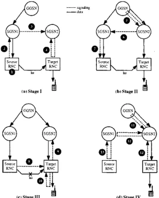
B. Core Nrm~orX Bi-casting (CNB)
11. SGSN? sends a
Update-PDP-Context
.Request
message to the GGSN. Based on the received ines- sage. the GGSN updates the corresponding PDP con- text and returns a Update.PDP.Context.Response message to SGSN?. Then the downlink packet rout- ing path is switched from the old path to the newFigure 4 shows the four stages of the CNB procedure when the communicating UE moves from the source RNC to the target RNC. Stage I (Steps 14: Figurc 4 (a)) is the same as Stage I in SD. which requests the target RNC to allocate the necessary resources for relocation.
In Stage I1 (Figure 4 (h)). the downlink packets are dupli- --- Slg"dl"8
--dm
RNC cated at the GGSN. and are sent to the target RNC through
both the old palh <GGSN-SGSNl-source RNC-target RNC> and the new path <GGSN--SGSN2+target RNC>. The following stcps are executed.
5 . Upon receipt of the Relocation-Request- Acknowledge message at Step 4. SGSN2 sends a Update.PDPContext-Request message that requests the GGSN to bi-cast the downlink packets. 'The GGSN starts to perform hi-casting and replies SGSN2 a message Update.PDP.Context.Response. At this moment. the downlink packets
are
simultaneously transmitted to the targct RNC through the old and the new paths. Since the target RNC has not taken the SRNC role (i.e.. the target RNC has not received the Relocation-Commit message), the packcts routed through the new pathare
discarded at the targetRNC. RNC
These steps are used to inform the source RNC that all necessary resources are allocated, which are similar to Steps 5 and 6 in the SD approach.
RNC
6-7.
Fip. 5. The F-I SRNC Relocation (FSR) Approach In Stage Ill (Figure 4 (c)), the Iur link berwecn the source
RNC and the target RNC is disconnected, and the downlink
packets arriving at the source RNC are discarded. 111. FAST SRNC RELOCATION ( F S R ) S-10. These steps
are
used to move the SRNC role fromthe Fource RNC to the target RNC. which are similar to Steps 8-10 in the SD approach.
In Stage IV (Figure 4 (d)), the GGSN is informed to stop downlink packet hi-casting. The target RNC takes the SRNC role to transmit the downlink packets to the UE.
11. Through the Update.PDP.Context.Request mes- sage. SGSN2 informs the GGSN to stop downlink packet hi-casting. Then thc GGSN removes the GTP
tunnel between the GGSN and SGSNI, and replies SGSN? the Update.PDP.ContextLResponse mes- sage.
12. With the RelocationComplete message. the target RNC informs SGSN? that the relocation procedure is successfully performed. Then SGSN? exchanges this information with SGSNl using the FotwardRelocation.Complete and Foward.Relocation.Complet e Acknowledge message pair.
Finally. SGSNl and the source RNC exchange the lu.Release.Command and 1u.Release.Complete message pair to release the lu connection in the old path.
13.
This section describes the FSR approach and compares this approach with SD and CNB. As shown in Figure 2 (b). the UE is connected to the source RNC and SGSNl before SRNC relocation. After relocation. the data packets for the UE are directly routed through the target RNC and SGSN?
as
shown in Figure 2 (c). Figure 5 illustrates the four stages of the FSR procedure.Stage I (Figure 5 (a)) initiates SRNC relocation. In this stage. the routing path of downlink packcts is <GGSN--SGSNI-source RNC -target RNC-UE>. The following steps are executed in Stage 1.
1-2. When the Node B of the source RNC no longer
connects to the UE. the source RNC initiates SRNC relocation and sends the ID of the target RNC to SGSNI through the Relocation-Required message. Based on the ID of the target RNC, SGSNl de- termines that it is inter-SGSN SRNC relocation. SGSNl requests SGSN? to allocate the resources for the UE through the Forward_Relocation.Request message.
4. SGSNZ and the target RNC exchange the Relocation.Request and Reloca- tion.RequestAcknowledge message pair to
allocate the necessary resources for the UE. 3.
In Stage II (Figure 5 (h)). the GGSN routes the down- link packets to the old path before receiving the Up- date.PDP.Context-Request message (Step 5 in Figure 5
(h)). The packets delivered through the old path are called “old” .packets. After the GGSN has received the Up- date.PDP.Context.Request message. the downlink packets
are
routed to the new path <GGSN-SGSN?-target RNC>. The packets delivered by the new path are called “new” packets. The “new” packets arriving at the target RNC arc buffered until the target RNC takes over the SRNC role. The following steps are executed in Stage 11.5 . Upon receipt of the Relocation.Request Acknowledge message. SGSNZ sends a Update-PDP.Context_Request message to the GGSN. Based on the received message- the GGSN updates the corresponding PDP context fields and returiis
a
Update- PDPContext-Response message to SGSN?. Then the downlink packet routing path is switched lrom the old path to the new path. At this stage. the “new” downlink packets arriving at the target RNC ilre buffered.SGSN? sends
a
Forward-Relocation Response message to SGSNl to indicate that all resources for the UE are allocated. SGSNl forwards this in- formation to the source RNC through the Reloca- t ion.Command message .6-7.
In Stage 111 (Figure 5 (c)), the Iur link between the source RNC and the target RNC is disconnected. The “old” downlink packets arriving at the source RNC later than the Reloca- tion-Command message (Step 7 i n Figure 5 (b))
are
dropped.In this stage. Steps 8-IO switch the SKNC role from the source RNC to the target RNC.
8. With the Relocation.Commit message.
the
SRNC context of the IJE is UansfeITed from the soilrcc RNC to the target RNC.9-10. The target RNC sends a Relocation.Detect mes- sage to SGSN?. At the same time. the target RNC sends ;1 RAN-Mobility-Information message
to the UE. which triggers the UE to send the up- link IP packets through the new path <UE-target
RNC-SGSN2-GGSN>.
By executing Steps 11 and I? at Stage IV (Figure 5 (d)). the target RNC informs
&e
source RNC that SRNC relocation is successfully performed. Then the source RNC releases the system resources for the UE.11. The target RNC sends the Relocation.Complete message to -SGSNZ; which indicates that SRNC relocation is successfully performed. Then SGSN? exchanges this information with SGSNl through the Forward-Relocation.Complete and Forward-Relocation_CompleteAcknowledge TAB1.E I C o M P i R I N G FSR WITH SU A N D C S B Packet Loss at Source RNC Packet Loss at Taqel RNC Pnchet Buffering. Extra Signaling No message pair.
Finally. SGSNl and the
source
RNC exchanges the 1u.Release.Comrnand and lu.Release.Complete message pair to release the Iu connection in the old path.I?.
Based
on
the above discussions. Table I compares FSR with SD and CNB. The following issues are addressed.Packet Duplication. During SRNC relocation. IP packets are duplicated at the source KNC in SD. Similarly. IP packets are duplicated at the GGSN in CNB. Packet duplication will significantly consume system resources. On the other hand. packet duplication is not needed in the FSR approach.
Packet Loss. Packet loss may occur in these three ap- proaches either at the source RNC or at the target RNC. For SD and FSR. the data packets arriving at the source RNC may he lost. In SD. the “old” packets are dropped at the source KNC when the data-forwarding timer expires (Step 13 in Figure 3 (d)). In FSR. the “old” packets
are
dropped if they arrive at the source RNC later than the Relocation-Commandmessage
(see Step 7 in Figure 5 (h)) does.For SD and CNB. the data packets may he lost at the target RNC. In SD. the target RNC discards the forwarded packets from the source RNC if these packets arrive at the target RNC earlier than the Relocation.Commit
message
does (Step 7 in Figure 3 (b)). In CNB. the duplicated packets may he lost at the target RNC because the packets from the new path are dropped before the target RNC hecomes the SRNC (see Step 5 in Figure 4 (h)). On the other hand. since the packet huft‘ering mechanism is implemented in FSR. the packets are not lost atthe target RNC.
Packet Buffering. To avoid packet loss at the target RNC. the packet buffering mechanism is implemented i n FSR. which is not found in both SD arid CNB approaches.
Out-of-order Delivery. In SD. two paths (i.e.. the forward- ing and new paths) are utilized to simultaneously transmit the
downlink packets (see Step I 1 in Figure 3 (d)). Since the transmission delays for these two paths are not the same. the packets arriving at the target RNC may not be in sequence. which results in out-of-order delivery. On the other hand. this problem does not exist in FSR and CNB because the target RNC id these two approaches only processes the packets from one path (either the old path or the new path) at any time.
ilnd the out-of-order packets are discarded (see Step 5 in
Figure 4 (b)).
Extra Signaling. The SD approach follows the standard SRNC relocation procedure proposed in 3G 23.060 141. The FSR approach reorders the steps of the 3G 23.060 SRNC relocation procedure. Both approaches do not intro- duce any exwa signaling cost. On the other hand. CNB ex- changes additional Update.PDP.Context-Request and Up- date.PDP.Context-Response message pair (see Step 5 in Figure 4) between the GGSN and SGSN?. which incurs extra signaling cost. Note that all three approaches can be imple- mented in the GGSN, SGSN and RNC without introducing new message types to the existing 3GPP specifications.
In conclusion. SD and CNB require packet duplication lhat will double the network traffic load during SRNC relocation. For the SD approach. it is not clear if the Iu link in the forward-
ing path can he directly established between two RNCs. If not. an indirect path <source RNC-SGSNI-SGSN2-target RNC> is required. Also, it is not clear if the target RNC will be informed to stop receiving the forwarded packets when the data-forwarding timer expires. Packet duplication is avoided in FSR. We note that packets may he lost during SRNC relocation for these three approaches. Packet loss can not be avoided in SRNC relocation if we want to support real-time applications. We will show that packet loss for FSR is not a serious problem in the following section.
IV. PERFORMANCE EVALUATION
As described in the previous section. the routing path of
the downlink packets for the UE is switched liom the old path <GGSN- SGSNI- source RNC-target RNC> to the new path <GGSN-SGSNZ+target RNC> after the GGSN receives the
Update.PDP.Context-Request
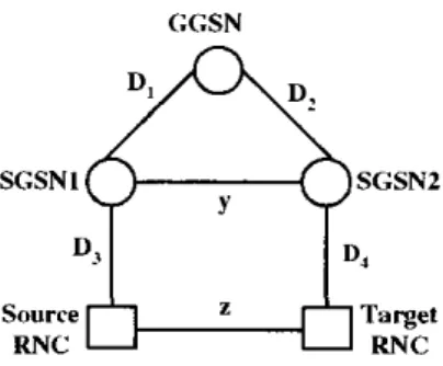
message (Step 5 in Figure 5 (h)). The packets delivered through the old path are lost if these packets arrive at the source RNC later than the Relocation.Cornrnand message does (Step 7 in Figure 5 (b)). Therefore, an important performance measure is the expected number of lost packets E [ N L ] during SRNC relocation. Fur- thermore. the packets transmitted through the new path are buffered at the target RNC if they m i v e at the target RNC earlier than the Relocation.Cornrnit message does (Step 8 in Figure 5 (c)). Hence another important performance measure is the expected number of buffered packets E [ N B ] during SRNC relocation.Figure 6 denotes the transmission delays among the net-
GGSN
Fiq. 6. The Transnission Delays
work nodes. which are represented by the random variables descrihed below.
.
U , : the transmission delay between the GGSN and SGSNl0 2 : the transmission delay between the CGSN and
SGSN2. Without loss of generality. we assume that
D1
and U2 have the same distribution.
.
Ds:
the transmission d e h y between SGSNl and the source RNCD4: the transmission delay between SGSN? and the target
RNC. Without loss of generality, we assume that U3 and
D., have the same distribution.
5: D2
+
Ds.D1
+LIS orDz
+
D4.
y: the transmission delay between SGSNl and SGSN2
.
z : the transmission delay hetween the source RNC andthe target KNC
Based on the above random variables. we develop an analytic model to derive the expected numbers of lost and buffered packets for FSR. Our analytic model has been validated against the simulation experiments. The simulation model follows the approach we developed in [IOl. and the details
are
omitted. In our analytic model. we assume that :E,and 2 have mixed-Erlang density functions
.I
where = 1
J = 1
L
0: X,, = O.Ol/E[z] \ 11.1-1 n.i? .FINL] 11.10 n.ns Il.(lG
1
D where ~ a z . , = 1 0=1The mixed-Erlang distribution is selected because this dis- tribution has been proven as a good approximation to many other distributions as well as measured data [71, [91. We also assume that h e inter-packet arrivals are a Poisson stream. and the inter-packet arrival times are exponentially distributed with the arrival rate A,.
We use numerical examples to investigate the performance
of E [ N L ] (i.e.. the expected number of lost packets) and
E [ N B ] (i.e.. the expected number of buffered packets) for
the FSR approach. In our experiments, the mixed-Erlang distributions for 3:. y. and .Ihave the parameters %.i = ay.i =
= 0.5 and m,,~ = mY.i = i i i = , , = 2 for i = 1 and 2.
Similar results are observed for other parameter values. which will not be presented here.
Figure 7 plots E [ i l i L I as a function of E [ y ] (i.e.. the expected number of ?J) ranging from O.BE[:c] to '?E[x]. The
E[!,] value is selected depending on whether the SGSNs
are located in the same network or different networks. If the two SGSNs are in the Same network, the transmission delay Ely] is the same as that between the G t X N and the SGSN. Thus E [ y ] 2 0.5E[n:]. If these SGSNs are in the different networks. E[y] 2 '?E[:I:] may he appropriate. Depending on the applications being investigated. we consider X, = O.l/E[:c]. O.W/E[:c] and O.Ol/E[s]. Note that the
1.00
:;,so
~ 3.00 ~ x :x,,
= O.l/E!.I:] 0 :x,
= 0.02/E[:c] 0: A,, = O.OI/E[c] 1.50 - 1 .00I
1
n o n100 Mbps Fast Ethernet and 155.52 Mbps STM-UATM have been commonly adopted lor Gi (hetween the GGSN and the SGSN) and Iu (between the SGSN and the RNC). For real- time applications such as VnIP and video streaming services. the packet size typically ranges from 200 to 1500 bytes. and the inter-packet arrival time ( l / A a ) ranges from 10 to 40 ms. Therefore. our study selects the A,, values in the range
[w,
&]
. Ftgure, 7 shows intuitive results that E [ N L ] isan increasing tunction ot A,. and LS
a
decreasing function of E [ g ] . We also observe that E[Nr,] is more sensitive toE[:/] for small A, than large A,. This figure indicates that the
E [ N L ] performance is reasonably good. For example. when
E[{,] = E[:c]. the expected number nf lost packets E [ N L ] for
VnIP application (i.e.. A,, = O.Ol/E[:c]) is 0.006. For video streaming services (i.e.. A, = O.l/E[z]). E[N,c] = O.0D.
Also. when Ely] increases from E[:cl to 2E[:c]. E [ R r ~ ] is
significantly reduced (i.e., 51%. 52% and 55% reductions for words. the FSR performance can be improved by increasing the speed of the "3:" link over the "y" link.
A" = O.l/E[z], O.O'?/E[rc]. 0.01/E[ respectively). In other
Figure Y shows the effects of E [ g ] and
A,
nn E[:VB], where X,, = O.l/E[:c], O.O'/E[z] and O.Ol/E(:c]. In this figure. we consider Ely] = E[:] that ranges from O.iE[:c] to %[:cl. This tigure intuitively indicates that E j N B ] increases as E[$] and X, increase. Similar to what we nbserved in Figure 7. the E[:VUI performance is more sensitive to E[y] for small A,than large X,. Since the expected number of buffered packets at the target RNC is below 3.5 for all cases considered in our
study. it is clear that the packet buffering mechanism does not result in long packet delay (due to queuing).
[I01 Lm. Y.-B.. Chcne. H.-Y. Cheng. Y.-II.. and Aorawal. P.. . Implcmcnting Auiomattrc Lwalion Uplalc fbr Folluw-M6 Database usins VolP and Bluetooth T<:hnulogi<s. IEEE Trms. on Cunipururs. 51(10):1154-116X. In 3GPP TR 25.936. SRNC dupliculion (SD) and cure
network hi-curline (CNB) were nronosed to S U D D O ~ real-time
1002.
,111 ~ i " . Y.B.. H ~Y.R.. paag. A.-c. ~ ~ ~ and aInmtac. . Imich. MI- IP Approach for 7hkd Gcncmtion Mobile Networks IEEE Nehuork. l6(5):&19, 2002.
Y I . .I
multimedia services in the UMTS all-1P network. Both aP- proaches require packet duplication during SRNC relocation. which significantly consume the system resources. This paper proposed afust SRNC relocation (FSR) approach that provides real-time SRNC switching without packet duplication. In FSR, the packet buffering mechanism is implemented to avoid packet loss at the target RNC. We developed an analytic model to investigate the performance of FSR. which was validated against the simulation experiments We note that packet loss cannot he avoided during SRNC relocation if we want to support real-time multimedia traffic in the UMTS all- IF' network. Our performance study indicated that packet loss at the source RNC can be ignored in FSR. Furthermore. the expected number of buffered packets at the target RNC is small, which does not result in long packet delay. FSR can be implemented in the GGSN, SGSN and RNC without intro- ducing new message types to the existing 3GPP specifications. As a final remark, the FSR approach is a US and
an
ROC pending patents.ACKNOWLEDGMENT
This work was sponsored in part by the MOE Program for Promoting Academic Excellence of Universities under grant number 89-E-FA04- 1-4, Chair Professorship of Providence University, IIS/Academia Sinica. the Lee and MTI Center for Networking ResearchNCTU: National Science Council under contract NSC92-2213-E-002-049. CCIJITRI under contract TI-92021-6. Microsoft and Intel.
REFERENCES
I
[I] 3GPP. 3rd Generation Paitncrship Projcd: Technical Spzcificalion Group Services and Systems Aspects: Acchileiluvl for an All IP Ndwork Tschnical Report 3G TR 23.922 version 1.0.0 (1999.10). 1999. [?I ?GPP. 3rd Fendration Partnership Projea: Tzchnical Specificalion Group Radio Accest Nc twwk UTRAN Iu Inlerface RANAP Signaling for Rzlcasz 1999. Technical Specification 3G TS 25.411 version 3.40
131 3GPP. 3rd F a n m i i o n Pvnnzrship Pro~scl: Technical Specification Group RAN 3; Handovers for rzal-lime services from PS domain . Techtical Report 3G TR 25.936 version 4.0.1. 3GPP. 2M)I.
[4l 3GPP. 3rd Generation Partnership Projcd: Technical Specification Group Scrviczs and Systems ASPCIS: General Packet Radio Service (GPRS): Service Dccriplion; Stage 1. Techtical Specification 3G TS 23.0M v m i o n 4.1.0 (2001-06). 1001.
[SI 3GPP. 3rd Generation Partnership Project: Technical Specificauon Group Services and Syslcms Aspecu: Network Archilecture. Terhnicnl
Snecificvlion 3G TS 13.002 version 5.3.0 (2001-06). 1WI.
(2000-12). 2000.
161 Bos. L.. and Leroy. S. Toward at1 All-IP-has4 UMTS System Archi- [71 Fang. Y.. 2nd Chlamtac. 1. Tclctraffic Analysis and Mohility Mudding
for PCS Networks. IEEE Twmsnclions on Cornmsnimrio?rs. 47(7):1062-
~ Z C I U ~ Z . IEEE NI.ICO,B. I~(I):~MS. x o i
1072. July 1999.
[XI Holma. H.. and Toslwln. A. (edited). WCDM.4 for UMTS. John Wiley L sons. 2ooo.
![Figure 7 plots E [ i l i L I as a function of E [ y ] (i.e.. the expected number of ?J) ranging from O.BE[:c] to '?E[x]](https://thumb-ap.123doks.com/thumbv2/9libinfo/8777472.214345/8.920.507.829.102.422/figure-plots-e-function-expected-number-j-ranging.webp)
