國 立 交 通 大 學
生醫工程研究所
碩
士
論
文
無線居家睡眠多項生理監測儀之
基於安全網路連線的遠端監測系統開發
The Development of Wireless Household Polysomnography
Remote Monitoring System over Secure Network Connection
研 究 生:黃聖翔
指導教授:蕭子健
無
線
居
家
睡
眠
多
項
生
理
監
測
儀
之
基 於 安 全 網 路 連 線 的 遠 端 監 測 系 統 開 發
The Development of Wireless Household Polysomnography
Remote Monitoring System over Secure Network Connection
研 究 生:黃聖翔 Student:Sheng-Hsiang Huang
指導教授:蕭子健
Advisor:Tzu-Chien Hsiao
國 立 交 通 大 學
生 醫 工 程 研 究 所
碩 士 論 文
A ThesisSubmitted to Institute of Biomedical Engineering College of Computer Science
National Chiao Tung University in Partial Fulfillment of the Requirements
for the Degree of Master
in
Computer Science August 2010
Hsinchu, Taiwan, Republic of China
無
線
居
家
睡
眠
多
項
生
理
監
測
儀
之
基 於 安 全 網 路 連 線 的 遠 端 監 測 系 統 開 發
研 究 生:黃聖翔
指導教授:蕭子健
國 立 交 通 大 學
生 醫 工 程 研 究 所
摘 要
阻塞性睡眠呼吸中止症(OSA)與睡眠障礙的臨床診斷過程,要求受測者在睡 眠檢查中心配戴多項生理監測儀(PSG)進行訊號記錄。然而,常見白袍症、睡眠 適應的影響下,睡眠技師無法採用此數據,進而影響診斷之正確性,為此,家用 型 PSG 因應而生。其具備操作簡便、價格低廉優點,但卻仍有其診斷限制,例 如,離線資料記錄之完整性、受測環境不確定性、電極鬆脫、非正常中斷檢測等 診斷限制。 許多研究團隊已投入諸多資源來克服上述限制,並期待提升功能後以利睡眠 技師的即時介入。基於此研究課題與診斷需求,本研究將整合 TCP Socket Connection 功能,研發一套家用型 PSG 遠端監測系統。其中亦考量個人生理健 康狀況與檢測隱私之保護,連線係是採用數位彌封結合數位簽章技術,確保資料 即時傳送之保密性與完整性。 在與上一版本之 PSG 系統的量測結果評估上,我們得到的很高的相似係數 (98.25%),表示新版本的 PSG 系統在置換掉原系統的軟體部分後,還是保持著很 高的量測效能。而新版本的 PSG 系統在自身的效能評估上,亦有很好的實驗結料丟失率,2) 具安全性的網路連線在 CPU 負載上只較一般的網路連線增加 5.18%的負載,3) 實際所佔用的網路頻寬也只增加 4.82%,4) 網路資料的竊聽者 幾乎無法竊取傳送中的生理訊號,5) 達成資訊安全目標中的資料機密性與資料 完整性。基於以上的實驗結果,我們可以證明所提出的 PSG 系統擁有很好的效 能及安全性。此外,為了建置與睡眠中心更相似的睡眠檢測環境,我們重新設計 了軟體架構,使其達到多重PSG Client 的目的,讓 PSG Server 可同時監測多台 PSG Client 的訊號量測,就像在睡眠中心裡睡眠技師在控制室中監測多個病房裡 各個受測者之量測結果的情境。 在傳統家用型 PSG 的使用上存在著諸多的診斷限制,而本研究為了克服這 些診斷限制所提出的基於安全網路連線的家用型 PSG 遠端監測系統,根據我們 的實驗結果,確實可讓睡眠技師跨越空間的障礙,對於受測者量測之生理訊號作 即時且安全的監控。本研究成果可應用在居家睡眠的長期追蹤研究,提供家用 PSG 的使用者更高品質的睡眠檢測。 期許本研究可對長期患有睡眠障礙之患者作出一定程度之貢獻。
The Development of Wireless Household Polysomnography
Remote Monitoring System over Secure Network Connection
Student: Sheng-Hsiang Huang
Advisor: Tzu-Chien Hsiao
Institute of Biomedical Engineering College of Computer Science
National Chiao Tung University
Abstract
The diagnosis of Obstructive Sleep Apnea (OSA) and sleep apnea, subject is required to use polysomnography (PSG) recording the bio-signal. However, base on the influence of white coat syndrome and unfamiliar environment, sleep physician can’t adopt the data. It will affect the accuracy of diagnosis. Therefore household PSG is produced for above reason. Household PSG has the advantages of less technical complexity and lower cost. But it still exist diagnostic limitations (e.g. integrity of off-line data, uncertain experimental environment, electrode loose, abnormal terminate of examination, etc.)
There are many research teams invest much resources to overcome above limitations, and expect that it can let sleep intervene the examination immediately after the function upgraded. Base on this research issue and requirement of diagnosis, in this study, we will research and develop a household PSG remote monitoring system that integrated TCP Socket Connection. Base on the protection of personal privacy and state of health, the connection combined Digital Envelope with Digital Signature. It ensures the data confidentiality and data integrity.
To compare with last PSG system, we obtain a very highly correlation coefficient (98.25%) on the evaluation of measurement results. It means new proposed PSG system keep a highly performance of measurement after replace the software of last PSG system. And on itself performance evaluation of new proposed PSG system, it also obtain a very well experimental results. 1) Transmission has 0% data lose, 2) CPU loading only increases 5.18%, 3) actual average occupied bandwidth just increases 4.82%, 4) the eavesdropper can’t eavesdrop the bio-signal almost and 5) it achieve the goals of information security: data confidentiality and data integrity. Base on above experimental results, we could confirm our proposed PSG system that have very well performance and security. Besides, in order to set up a similar examination environment, we improve our software to the multiple client architecture. This architecture let PSG Server can monitor several PSG Clients simultaneously just like sleep physician in control room supervises patients in individual rooms in sleep laboratory.
There exist many diagnostic limitations on using traditional household PSG. In this study in order to overcome the diagnostic limitations, we propose a household PSG remote monitoring system over secure network connection. According to our experimental results, it’s truly let sleep physician strides across the barriers of space to supervise the bio-signal recording by subject immediately and safely. Our study can serve for a long-term tracing and research of personal sleep monitoring at home, and provide patient have a more high-quality sleep examination.
誌 謝
本論文的完成,首先要感謝指導教授蕭子健博士的悉心指導,讓我獲得許多 臨床上與技術上寶貴的知識,且無論在研究方法及做人處事的學習上都受益良 多,而在論文撰寫的過程中,也是以亦師亦友的角色不斷給予我鼓勵和信心,使 得我可以順利的完成本論文。另外也要感謝口試委員:台北榮民總醫院蘇東平副 院長、國家衛生研究院陳聖夫博士、成功大學蘇文鈺博士、交通大學林進燈教務 長、交通大學林伯昰博士的建議與指教,使得本論文更為完整。特別要感謝蘇東 平副院長和林伯昰博士,蘇副院長給予我醫學上寶貴的建議,使得本研究可以更 貼近實際臨床上的應用;林博昰博士在工程上的角度給予我指導,使得本研究中 的系統可以擁有最佳的執行效能。 感謝我的父母親對我的教育與栽培,哥哥哲忠和姊姊崇珍對我的關心與鼓 勵,感謝你們給予我精神及物質上的一切支援,使我能安心地致力於學業,在交 通大學順利的取得碩士學位。 感謝實驗室的同學育航、智賢、佩瑄、璽文、佳鈴、敬婷,在過去兩年研究 生活中同甘共苦、相互扶持,及學姐家欣與學長怡然、有德、哲睿,學弟妹們麒 宇、琬茹、俊甫,在研究過程中所給我的鼓勵與協助。碩士生涯的二年因你們而 精彩。 最後我要感謝我的女友姿繻,感謝妳這七年來對我的陪伴與關心,參與我人 生中一個個重要的過程。在我高興時分享我的喜悅;在我失意時給予我安慰。因 為有妳做我的後盾,幫我打理生活一切瑣事,我才能全心投入完成本論文。 謹以本論文獻給我的家人及所有關心我的師長與朋友們,謝謝你們。 也祝福好友韶筠可以早日脫離癌症病魔的纏身,早日康復。Acknowledgement
For completion of this thesis, first I would like to express my sincere appreciation to my advisor, Dr. Tzu-Chien Hsiao, for your guidance let me could gain much precious knowledge which on clinic and technic. I have benefited greatly from your guidance in research method and deal with people. And in the process of thesis writing, you give me encouragement and confidence continuously in role of mentor, let me can complete this thesis successfully. Besides, I would appreciate my final examination committee members: Dr. Tung-Ping Su, Dr. Chin-Teng Lin, Dr. Sheng-Fu Chen, Dr. Wen-Yu Su and Bor-Shyh Lin, your suggestions and advices let this thesis could get more integrity.
I would express my gratitude to my family. Thanks for your whole support to me in spiritual and material, Let me can finish my Master degree successfully in NCTU.
I would appreciate all members in the Lab706: Roy, Wilson, Egg, His-Wen, Apple, Stela, Vera, Double, Yute, Dato, Chi-Yu, May, Chun-Fu. Thanks for your encouragement and assistances to my progress in research.
Finally, I would like to express my sincere appreciation to my girl friend, Tzu-Ju Peng, thank you accompany me and care for me for seven years, join in every important process of my life. Share my pleasure when I am delighted and offer me consolation when I am frustrated. Because of you help me take care every chore in life, I just can complete this thesis wholeheartedly.
I would like to dedicate this thesis to my family and all friends and teachers that concerned about me, thank you.
I also wish my good friend, Shao-Yun Wu, she can early keep the cancer away and quick return to good health.
Contents
摘 要 ... iii Abstract...v 誌 謝 ...vii Acknowledgement ... viii Contents ...ix List of Tables...xi List of Figures...xii Chapter 1 Introduction...11.1 Obstructive Sleep Apnea (OSA) ...1
1.2 Portable PSG...3
1.3 Motivation...6
1.4 Objective ...7
Chapter 2 Materials and Methods...8
2.1 The situation of use...8
2.2 Bio-signals ...9
2.3 European data format...15
2.4 Network socket connection...19
2.5 Security issue ...23
2.5.1 Encryption algorithm and one-way hash function ...23
2.5.2 AES symmetric encryption algorithm...26
2.5.3 RSA asymmetric encryption algorithm...32
2.5.4 SHA-1 hash function...34
2.5.5 Digital Envelope and Digital Signature ...35
2.6 System software design...39
2.6.1 Development environment...39
2.6.2 MSP430 packet format...40
2.6.3 PSG Client design ...42
Chapter 3 Experiment and Results ...56
3.1 Performance comparison between proposed and last PSG system...56
3.2 Performance analysis of PSG client/server...62
3.3 CPU loading analysis...64
3.3.1 CPU loading analysis of secure / normal network connection ...64
3.3.2 CPU loading analysis of encryption / decryption function in detail ...65
3.4 Occupied bandwidth analysis of secure / normal network connection...67
Chapter 4 Discussion...71
4.1 Why adopt RSA and AES as encryption algorithm for our secure network connection...71
4.2 Simulate network packet is intercepted situation...73
4.3 Achieved goals of information security...77
4.4 Multiple client architecture ...78
4.5 Online video monitoring...80
Chapter 5 Conclusion ...81
Chapter 6 Future work ...83
List of Tables
Table 1.1: AASM Classification of Types of Portable PSG (>6 h)...3
Table 1.2: Myths about household PSG[14]. ...6
Table 2.1: Common band of EEG[16] ...10
Table 2.2: Detailed digital format of the EDF header record[15]...18
Table 2.3: Summary of functions provided by the Berkeley sockets API library[20]. 20 Table 2.4: The features analysis of symmetric and asymmetric encryption algorithm24 Table 2.5: The parameter of EDF header...46
Table 3.1: CPU loading (%) information...64
Table 3.2: Analysis of execution time in encryption / decryption functions in detail. 66 Table 3.3: Actual average transmission rate (KB/5sec) ...68
List of Figures
Figure 1.1: Normal people and OSA patient...2
Figure 1.2: Watch-PAT 100, Itamar Medical, Framingham, Massachusetts...5
Figure 2.1: The situation of use ...8
Figure 2.2: Nonin Onyx® 9560, Nonin Medical Inc...9
Figure 2.3: Self-developed portable PSG...9
Figure 2.4: The recommended derivations of EEG (a) C4-M1; (b) O2-M1[18]. ...11
Figure 2.5: The recommended derivations of EOG[18]. ...11
Figure 2.6: The EMG electrodes position[18]. ...12
Figure 2.7: A single modified ECG Lead II use torso electrode placement[18]...13
Figure 2.8: The nasal airflow sensor is placed to record breathing during sleep[19]. .14 Figure 2.9: The pulse oximetry sensor position...14
Figure 2.10: TCP socket architecture...22
Figure 2.11: The SubBytes step diagram[27]. ...28
Figure 2.12: The ShiftRows step diagram[27]...29
Figure 2.13: The MixColumns step diagram[27]. ...30
Figure 2.14: The AddRoundKey step diagram[27]...31
Figure 2.15: Operations of SHA-1[31]. ...35
Figure 2.16: Digital Envelope architecture...36
Figure 2.17: Digital Signature architecture...37
Figure 2.18: The architecture combined Digital Envelope and Digital Signature...38
Figure 2.19: .NET Framework Platform architecture[33]. ...40
Figure 2.20: MSP430 transmits packet format in one minute. ...41
Figure 2.21: Header information contrast table. ...41
Figure 2.22: Dividing process of converted digital signal...42
Figure 2.23: Procedure of PSG Client. ...44
Figure 2.24: Bluetooth Search Module of PSG Client. ...44
Figure 2.25: Network Connect Module of PSG Client...45
Figure 2.26: Subject Info Get Module of PSG Client...46
Figure 2.28: Display Module of PSG Client...48
Figure 2.29: Encryption Module of PSG Client. ...49
Figure 2.30: Data Record Module of PSG Client...50
Figure 2.31: Procedure of PSG Server...51
Figure 2.32: Network Connect Module of PSG Server. ...52
Figure 2.33: Decryption Module of PSG Server...53
Figure 2.34: Stream Input Module of PSG Server...53
Figure 2.35: Display Module of PSG Server. ...54
Figure 2.36: Data Record Module of PSG Server...55
Figure 3.1: Stage W...57
Figure 3.2: Stage N1. ...57
Figure 3.3: Stage N2. ...58
Figure 3.4: Stage N3. ...58
Figure 3.5: Stage R. ...59
Figure 3.6: Correlation examples[35]. ...60
Figure 3.7: The waveform of EOG between proposed PSG and last PSG, and their correlation coefficient in every 1 second...61
Figure 3.8: Subject 1, whole night EOG signal, 2010/06/04 Comparison between PSG Client and PSG Server ...63
Figure 3.9: Subject 2, whole night EOG signal, 2010/06/07 Comparison between PSG Client and PSG Server ...63
Figure 3.10: CPU loading curve. ...65
Figure 3.11: Diagram of execution time in encryption / decryption functions in detail...66
Figure 3.12: Occupied bandwidth analysis of the secure network connection...69
Figure 3.13: Occupied bandwidth analysis of normal network connection...69
Figure 3.14: The actual value / theoretical value comparison between the secure network connection and normal network connection in the PSG Client. ...70
Figure 3.15: The actual value / theoretical value comparison between the secure network connection and normal network connection in the PSG Server...70
Figure 4.2: The cracking process of PSG signal...74
Figure 4.3: Network packet analyze for secure network connection...75
Figure 4.4: The PSG signal has been encrypt and send to PSG Server. ...75
Figure 4.5: The simulate signal received from PSG Client and haven’t decrypt...76
Figure 4.6: The snapshot of multiple client system. ...78
Figure 4.7: Multiple client architecture. ...79
Chapter 1 Introduction
1.1 Obstructive Sleep Apnea (OSA)
Sleep is a natural state of bodily rest observed in humans and other animals. A sleep disorder is a medical disorder of the sleep patterns of a person or animal. Sleep Apnea is a condition where a person periodically stops breathing during sleep. This causes the person to wake up dozens of times during the night, but in most cases they are unaware of this disruption. The most common type of sleep apnea is Obstructive Sleep Apnea (OSA), which is caused by closure of the airway.
OSA is present in 2–4% of middle-age adults[1], and is associated with symptoms such as daytime somnolence and serious complications and risks, such as hypertension[2], heart failure[3], stroke[4], diabetes[5], metabolic abnormalities[6], motor-vehicle accidents[7] and mood disorders[8]. It has direct impact on the patient’s quality of life. The drawing to the right shows the airway of a healthy individual (left) and an OSA patient (right). The healthy patient is breathing normally with the airway open, but the OSA patient's airway is closed, with the arrows showing the blockage [Figure 1.1]
Figure 1.1: Normal people and OSA patient
Continuous positive airway pressure (CPAP) is the most commonly prescribed treatment and successfully treats OSA in the majority of patients[9]. The present accepted standard for OSA diagnosis is a PSG in the sleep laboratory. But based on some reasons, such as white coat syndrome and unfamiliar environment, OSA diagnosis results sometimes can’t be supported from physician in sleep laboratory PSG. Thus technological advances led to the commercial availability of portable PSG that produce credible household PSG.
1.2 Portable PSG
The American Association of Sleep Medicine (AASM) published initial practice parameters regarding the use of portable PSG devices in the assessment of OSA in 1994[10]. Many studies have been carried out for OSA screening attempting to reduce PSG cost and complexity. Different techniques have been proposed, oximetry-based screening being one of the most widely suggested for both the adult and pediatric population. Although these methods have high sensitivity, they tend to have very low specificity[10]. The society classified sleep apnea evaluation studies based on the number of channels or signals that the monitor employed, categorized from type I to type IV. A minimum of 6 hours of recording time was recommended when using any of the configurations. AASM classification of types of portable PSG is shown as Table 1.1.
Table 1.1: AASM Classification of Types of Portable PSG (>6 h)
Type of Portable PSG Type I (attended) Type II (unattended) Type III
(modified, for diagnosing OSA)
Type IV (1 or 2 channels) Measurement channels ≥ 7 ≥ 7 ≥ 4 1 or 2 Measurements 。EEG 。EOG 。EMG (Chin) 。EKG 。Air flow 。Respiratory effort 。Pulse oximetry 。EEG 。EOG 。EMG (Chin) 。EKG 。Air flow 。Respiratory effort 。Pulse oximetry 。EKG 。Air flow 。2 * respiratory-effort 。Pulse oximetry 。Peripheral arterial tonometry 。Pulse oximetry 。Air flow or chest movement
Body position Documented or objective Possible Possible No Leg movement EMG or motion sensor Optional Optional No
Personnel Yes No No No
Intervention Possible No No No
Type I monitoring consists of full overnight PSG, with a minimum of two channels each for EEG, chin EMG, EOG, as well as respiratory airflow, respiratory effort
(thoracic and abdominal breathing movements), oximetry, and ECG or heart rate monitoring. These studies are fully attended by a technologist and are typically conducted in a sleep laboratory.
Laboratory-based PSG forms the framework upon which the field of sleep disorders medicine has been built over the last 40-50 years. For the standard test the patient comes to a sleep lab in the early evening, and over the next 1-2 hours is introduced to the setting and "wired up" so that multiple channels of data can be recorded when he/she falls asleep. The sleep laboratory may be in a hospital, a free-standing medical office, or in a hotel. A sleep physician should always be in attendance and is responsible for attaching the electrodes to the patient and monitoring the patient during the study. After the test is completed a 'scorer' analyzes the data by reviewing the study in 30 second 'epochs'[11].
Portable studies (type II to IV) are summarized as follows: type II consists of an equivalent number of channels as type I, with the singular difference being that the study is not attended by a physician. Like type I studies allow for the identification and quantification of sleep stages. Using the Sleep Heart Health Study (SHHS) methodology and technology, Iber and colleagues[12] recruited 76 participants from the general community to volunteer for recordings both in the laboratory and at home. Subjects were randomized with respect to recording order and were monitored with the same type II device used for the SHHS cohort From this study, Using SHHS methodology, median RDI was similar in the unattended home and attended laboratory setting with differences of small magnitude in some sleep parameters. Differences in RDI between settings resulted in a rate of disease misclassification that is similar to repeated studies in the same setting.
and one channel for cardiac monitoring. The study design consisted of simultaneous recording with the portable PSG and traditional in-laboratory PSG, followed by an at-home assessment with the same portable PSG. While the in-laboratory RDI and home RDI recorded from the type III monitor demonstrated no difference, the AHI generated from the in-laboratory PSG was significantly different.
Type IV is made up of only one or two channels, typically including oxygen saturation or airflow. Pittman and colleagues tested a novel type IV monitoring device (Watch-PAT 100, Itamar Medical, Framingham, Massachusetts, Figure 1.2) against traditional in-laboratory PSG[13]. The Watch PAT is wrist-worn device that collects peripheral arterial tonometry and oxygen saturation data, coupled with actigraphy
Figure 1.2: Watch-PAT 100, Itamar Medical, Framingham, Massachusetts.
Portable PSG were developed because of several recognized advantages over sleep-laboratory PSG, including sleep in a more familiar and flexible environment (home, mobile in-patient, hotel); fewer monitor leads; more convenience for patients with transportation problems; probably less disrupted sleep; less technical complexity; and lower cost. But portable PSG also have some disadvantages, including provides less information to a physician, exist several diagnostic limitations[14].
1.3 Motivation
There are several myths about the benefits of portable PSG (Table 1.2)[14]. There is a myth that is “Household PSG is more cost-effective” among this table. Household PSG is low cost usually, but lower cost isn’t equal to more cost-effective. The reason is that although it lost cost, but that means we couldn’t get more information in PSG diagnosis simultaneously. The raw data recorded by portable PSG maybe useless in the state that the sleep physician can’t control the sleep examination. The electrode could be loose, which lead to the interruption of signal reception and failed experiment. In order to increase the availability of experimental data, sleep physician requires more intervention.
Table 1.2: Myths about household PSG[14]. 。Sleep-laboratory PSG availability is limited
。Change in Medicare/Medicaid National Coverage Decision will increase access to household PSG
。Household PSG is appropriate for all patients 。Household PSG is more cost-effective
。Physician can interpret household PSG results 。Patient outcome same as sleep-laboratory studies
1.4 Objective
In order to physician can get more control in household PSG, we hope improve household PSG to a remote monitoring system, doing a real-time sleep examination under sleep physician supervising. It can ensure the recorded data which has data usability and data integrity. Data are written in a binary file following by the standard EDF (European Data Format), a standard file format designed for exchange and storage of medical time series[15].The exchange format can import to other software to analyze sleep disorder and score sleep stage by specialist.
Electronic Health Record (EHR) and personal health record (PHR) are an evolving concept defined as a systematic collection of electronic health information. It is a record in digital format that is capable of being shared across different health care settings, by being embedded in network-connected enterprise-wide information systems. According to above concept, at present standards formulated by related organizations including Digital Imaging and Communications in Medicine (DICOM), Health Level Seven (HL7), Integrating the Healthcare Enterprise (IHE), etc. Based on personal privacy protection, these standards all consider security issues. But unfortunately, these standards aren’t suitable using in real-time remote monitoring environment and PSG records don’t follow above standard. Therefore we have to establish a secure network connection that exclusively for PSG in real-time remote monitoring environment.
Chapter 2 Materials and Methods
2.1 The situation of use
Figure 2.1 showed the situation of use. The situation consists of subject, Bio-signal acquisition unit, secure network connection, sleep physician, PSG Client and PSG Server. First subject wears the bio-signal acquisition unit to get himself bio-signal, and then the signal that be processed by the unit will transfer to PSG Client via Bluetooth wireless. In the remote terminal, sleep physician monitor subject’s real-time signal by PSG Server, through the secure network connection from PSG Client. The raw data recorded by PSG Client and PSG Server will store in EDF format, the exchange format can import by other analysis software to scoring sleep stage.
Bio-signal Acquisition Unit
Secure Network Connection
Monitoring by physician
PSG Client PSG Server
Subject
2.2 Bio-signals
A PSG will record eight channels in our system. Two channels are for the Electroencephalogram (EEG), one measure airflow, one is for chin movements (EMG), two for eye movements (EOG), one for heart rate (EKG), one for oxygen saturation. The channel of oxygen saturation is recorded by Nonin Onyx® 9560 (Figure 2.2) that is a Bluetooth wireless fingertip pulse oximeter. The other channels are recorded by self-developed portable PSG (Figure 2.3).
A. Electroencephalogram
Electroencephalography (EEG) is the measurement of electrical activity produced by the brain as recorded from electrodes placed on the scalp. When measuring from the scalps, recorded the EEG signal is about 20-200uV for a typical adult human. And a common system reference electrode is connected to the other input of each different amplifier. These amplifiers amplify the voltage between the active electrode and the reference (typically 1,000–100,000 times, or 60–100 dB of voltage gain). The EEG is typically described in terms of rhythmic activity and transients. The rhythmic activity is divided into bands by frequency. The common band of EEG is shown as Table 2.1.[16]
Table 2.1: Common band of EEG [16]
Type Frequency (Hz)
Delta Up to 3Hz
Theta 4 – 7Hz
Alpha 8 – 13Hz
Beta 13 - 30Hz
In PSG system, the electroencephalogram (EEG) will generally use three "exploring" electrodes and two "reference" electrodes, unless a seizure disorder is suspected, in which case more electrodes will be applied to document the appearance of seizure activity. The exploring electrodes are usually attached to the scalp near the frontal, central (top) and occipital (back) portions of the brain via a paste that will conduct electrical signals originating from the neurons of the cortex. These electrodes will provide readout of the brain activity that can be "scored" into different stages of sleep (N1, N2, N3 which combined are referred to as NREM sleep and Stage R which is rapid eye movement sleep or REM, and Wakefulness). EEG electrode position is
determined by international 10-20 system[17]. The recommended derivations are shown as Figure 2.4[18].
Figure 2.4: The recommended derivations of EEG (a) C4-M1; (b) O2-M1[18].
B. Electrooculogram
The electrooculogram (EOG) uses two electrodes; one that is placed 1 cm above the outer canthus of the right eye and one that is placed 1 cm below the outer canthus of the left eye. These electrodes pick up the activity of the eyes in virtue of the electropotential difference between the cornea and the retina (the cornea is positively charged relative to the retina). This determines when REM sleep occurs, of which rapid eye movements are characteristic, and also essentially aids in determining when sleep occurs. The recommended derivations are shown as Figure 2.5[18].
C. Electromyogram
The Electromyogram (EMG) typically uses four electrodes to measure muscle tension in the body as well as to monitor for an excessive amount of leg movements during sleep (which may be indicative of Periodic Limb Movement Disorder, PLMD). Two leads are placed on the chin with one above the jaw line and one below. This, like the EOG, helps determine when sleep occurs as well as REM sleep. Sleep generally includes relaxation and so a marked decrease in muscle tension occurs. A further decrease in skeletal muscle tension occurs in REM sleep. A person becomes partially paralyzed to make acting out of dreams impossible, although people that do not have this paralysis can suffer from REM Behavior Disorder. Finally, two more leads are placed on the anterior tibialis of each leg to measure leg movements. The EMG electrodes position is shown as Figure 2.6[18].
Figure 2.6: The EMG electrodes position[18].
D. Electrocardiogram
Though a typical electrokardiogram (ECG or EKG) would use ten electrodes, only two or three are used for a polysomnogram. They can either be placed under the collar bone on each side of the chest, or one under the collar bone and the other six inches above the waist on either side of the body. These electrodes measure the electrical activity of the heart as it contracts and expands, recording such features as the "P" wave,
"QRS" complex, and "T" wave. These can be analyzed for any abnormalities that might be indicative of underlying heart pathology. The EKG electrodes position is shown as Figure 2.7[18].
Figure 2.7: A single modified ECG Lead II use torso electrode placement[18].
E. Nasal Airflow
Nasal and oral airflow can be measured using pressure transducers, and/or a thermocouple, fitted in or near the nostrils; the pressure transducer is considered the more sensitive. This allows the clinician/researcher to measure rate of respiration and identify interruptions in breathing. Respiratory effort is also measured in concert with nasal/oral airflow by the use of belts. These belts expand and contract upon breathing effort. The current guidelines recommend the use of a thermal sensor, which is placed in ht e patient’s nostril to detect the apnea; the nasal pressure transducer is used for identifying hyzone. Ideally, both the sensor and transducer should be used. The nasal airflow sensor position is shown as Figure 2.8[19].
Figure 2.8: The nasal airflow sensor is placed to record breathing during sleep[19].
F. Pulse oximetry
Pulse oximetry helps determine changes in blood oxygen levels that often occur with sleep apnea and other respiratory problems. The pulse oximetry fits over a finger tip or an ear lobe. The pulse oximetry sensor position is shown as Figure 2.9.
2.3 European data format
The European Data Format (EDF)[15] is a simple and flexible format for exchange and storage of multichannel biological and physical signals. It was developed by a few European 'medical' engineers who first met at the 1987 international Sleep Congress in Copenhagen. The EDF logo is derived from the congress logo which was the green pea from the fairy tale "The princess and the pea" by the Danish writer Hans Christian Andersen. With the support of Professor Annelise Rosenfalck, the engineers initiated the European (EC funded COMAC-BME) project on Sleep-Wake analysis (1989-1992). They wanted to apply their sleep analysis algorithms to each others data and compare the analysis results. So, on a morning in Leiden in April 1990, they agreed upon a very simple common data format. This format became known as the European Data Format. In August 1990, all participating labs had contributed an EDF sleep recording to the project.
EDF was published in 1992 in Electroencephalography and Clinical Neurophysiology 82, pages 391-393. Since then, EDF became the de-facto standard for EEG and PSG recordings in commercial equipment and multicenter research projects. One data file contains one uninterrupted digitized polygraphic recording. A data file consists of a header record followed by data records. The variable-length header record identifies the patient and specifies the technical characteristics of the recorded signals. The data records contain consecutive fixed-duration epochs of the polygraphic recording.
The first 256 bytes of the header record specify the version number of this format, local patient and recording identification, time information about the recording, the number of data records and finally the number of signals (ns) in each data record. Then
for each signal another 256 bytes follow in the header record, each specifying the type of signal (e.g. EEG, body temperature, etc.), amplitude calibration and the number of samples in each data record (from which the sampling frequency can be derived since the duration of a data record is also known). In this way, the format allows for different gains and sampling frequencies for each signal. The header record contains 256 + (ns * 256) bytes.
The information in the ASCII strings must be left-justified and filled out with spaces. Midnight time is 00:00:00. The duration of each data record is recommended to be a whole number of seconds and its size (number of bytes) is recommended not to exceed 61440. Only if a 1s data record exceeds this size limit, the duration is recommended to be smaller than 1s (e.g. 0.01).
The digital minimum and maximum of each signal should specify the extreme values that can occur in the data records. These often are the extreme output values of the A/D converter. The physical (usually also physiological) minimum and maximum of this signal should correspond to these digital extremes and be expressed in the also specified physical dimension of the signal. These 4 extreme values specify offset and amplification of the signal.
Following the header record, each of the subsequent data records contains 'duration' seconds of 'ns' signals, with each signal being represented by the specified (in the header) number of samples. In order to reduce data size and adapt to commonly used software for acquisition, processing and graphical display of polygraphic signals, each sample value is represented as a 2-byte integer in 2's complement format.
Gains, electrode montages and filters should remain fixed during the recording. Of course, these may all be digitally modified during replay of the digitized recording.
Below (Table 2.2) is the detailed digital format of the header record (upper block, ASCII’s only) and of each subsequent data record (lower block integers only). Note that each one of the ns signals is characterized separately in the header.
Table 2.2: Detailed digital format of the EDF header record[15].
Field name Size Field rules
Identification code 8 bytes Byte 1: "0" (ASCII) Local subject identification 80 bytes Bytes 2-8 : (ASCII) Local recording identification 80 bytes User text input (ASCII)
Start date of recording 8 bytes dd.mm.yy (ASCII)
Start time of recording 8 bytes hh.mm.ss (ASCII)
Number of bytes in header record
8 bytes (ASCII)
Version of data format. 44 bytes (ASCII)
Number of data records "-1" if unknown
8 bytes (ASCII)
Duration of a data record, in seconds
8 bytes e.g.: "1" (ASCII)
Number of channels (N) in data record
4 bytes e.g.: "257" or "128" (ASCII)
Labels of the channels N x 16 bytes e.g.: "Fp1", "Fpz", "Fp2", etc (ASCII)
Transducer type N x 80 bytes e.g.: "active electrode", "respiration belt" (ASCII) Physical dimension of
channels
N x 8 bytes e.g.: "uV", "Ohm" (ASCII)
Physical minimum in units of physical dimension
N x 8 bytes e.g.: "-32768" (ASCII)
Physical maximum in units of physical dimension
N x 8 bytes e.g.: "32767" (ASCII)
Digital minimum N x 8 bytes e.g.: "-32768" (ASCII) Digital maximum N x 8 bytes e.g.: "32767" (ASCII) Prefiltering N x 80 bytes e.g.: "HP:0,16; LP:500" Sampling rate N x 8 bytes e.g. "2048" (ASCII)
2.4 Network socket connection
In computer networking, network socket is an endpoint of a bidirectional inter-process communication flow across an Internet Protocol-based computer network, such as the Internet. The term Internet sockets is also used as a name for an application programming interface (API) for the TCP/IP protocol stack, usually provided by the operating system. Internet sockets constitute a mechanism for delivering incoming data packets to the appropriate application process or thread, based on a combination of local and remote IP addresses and port numbers. Each socket is mapped by the operating system to a communicating application process or thread.
A socket address is the combination of an IP address (the location of the computer) and a port (which is mapped to the application program process) into a single identity, much like one end of a telephone connection is the combination of a phone number and a particular extension.
An application programming interface (API), allows communications between hosts or between processes on one computer, using the concept of an Internet socket. It can work with many different I/O devices and drivers, although support for these depends on the operating-system implementation. This interface implementation is implicit for TCP/IP, and it is therefore one of the fundamental technologies underlying the Internet. It was first developed at the University of California, Berkeley for use on Unix systems. All modern operating systems now have some implementation of the Berkeley socket interface, as it became the standard interface for connecting to the Internet. There is a summary of functions provided by the Berkeley sockets API library shown as Table 2.3.[20]
Table 2.3: Summary of functions provided by the Berkeley sockets API library.[20] Function Explain
socket( ) creates a new socket of a certain socket type, identified by an integer number, and allocates system resources to it.
bind( ) typically used on the server side, and associates a socket with a socket address structure, i.e. a specified local port number and IP address.
listen( ) used on the server side, and causes a bound TCP socket to enter listening state.
connect( ) used on the client side, and assigns a free local port number to a socket. In case of a TCP socket, it causes an attempt to establish a new TCP connection.
accept( ) used on the server side. It accepts a received incoming attempt to create a new TCP connection from the remote client, and creates a new socket associated with the socket address pair of this connection.
send( ) / recv( ) used for sending and receiving data to/from a remote socket.
close( ) causes the system to release resources allocated to a socket. In case of TCP, the connection is terminated.
gethostbyname( ) / gethostbyaddr( )
Used to resolve host names and addresses.
select( ) Used to prune a provided list of sockets for those that are ready to read, ready to write, or that have errors.
poll( ) Used to check on the state of a socket in a set of sockets. The set can be tested to see if any socket can be written to, read from or if an error occurred.
getsockopt( ) Used to retrieve the current value of a particular socket option for the specified socket.
The Transmission Control Protocol (TCP) provides the concept of a connection, which is a stateful network association between two hosts with a variety of error correction and performance features. The following is divided into two sections (Server and Client) to explain the detailed steps of TCP socket connection. TCP socket architecture is shown as Figure 2.10.
Server
Setting up a simple TCP server involves the following steps:
1. Creating a TCP socket, with a call to socket( ).
2. Binding the socket to the listen port, with a call to bind( ). Before calling
bind( ), a programmer must declare a sockaddr_in structure, clear it , and
the sin_family(AF_INET), and fill its sin_port (the listening port, in network
byte order) fields. Converting a short int to network byte order can be done
by calling the function htons( )
3. Preparing the socket to listen for connections (making it a listening socket), with a call to listen( ).
4. Accepting incoming connections, via a call to accept( ). This blocks until an incoming connection is received, and then returns a socket descriptor for the accepted connection.
5. Communicating with the remote host, which can be done through send( ) and recv( ).
6. Eventually closing each socket that was opened, once it is no longer needed, using close( ).
Client
Setting up a TCP client involves the following steps:
1. Creating a TCP socket, with a call to socket( )
2. Connecting to the server with the use of connect( ), passing a sockaddr_in structure with the sin_family set to AF_INET, sin_port set to the port the endpoint is listening (in network byte order), and sin_addr set to the IP address of the listening server (also in network byte order.).
3. Communicating with the server by using send( ) and recv( ).
4. Terminating the connection and cleaning up with a call to close( ).
Server
socket( )
blocks until connection from client
Figure 2.10: TCP socket architecture
listen( ) accept( ) Client socket( ) connect( ) bind( ) Connection establishment recv( ) send( ) process request send( ) recv( ) data (request) data (reply)
2.5 Security issue
2.5.1 Encryption algorithm and one-way hash function
In cryptography, encryption is the process of transforming information (referred to as plaintext) using an algorithm (called cipher) to make it unreadable to anyone except those possessing special knowledge, usually referred to as a key. The result of the process is encrypted information (in cryptography, referred to as ciphertext). In many contexts, the word encryption also implicitly refers to the reverse process, decryption to make the encrypted information readable again (i.e. to make it unencrypted).
Encryption has long been used by militaries and governments to facilitate secret communication. Encryption is now commonly used in protecting information within many kinds of civilian systems. For example, the Computer Security Institute reported that in 2007, 71% of companies surveyed utilized encryption for some of their data in transit, and 53% utilized encryption for some of their data in storage[21].
Encryption is also used to protect data in transit, for example data being transferred via networks (e.g. the Internet, e-commerce), mobile telephones, wireless microphones, wireless intercom systems, Bluetooth devices and bank automatic teller machines. There have been numerous reports of data in transit being intercepted in recent years[22]. Encrypting data in transit also helps to secure it as it is often difficult to physically secure all access to networks.
Encryption algorithms divided into symmetric encryption algorithms and asymmetric encryption algorithms according to feature of the key. Symmetric algorithms are a class of algorithms for cryptography that use trivially related, often identical, cryptographic keys for both decryption and encryption. Asymmetric key
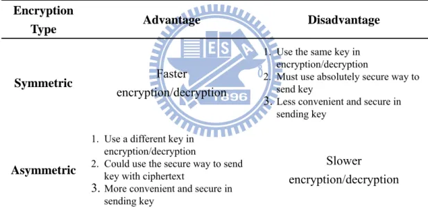
algorithms unlike symmetric key algorithms, it does not require a secure initial exchange of one or more secret keys to both decryption and encryption. It is used to create a mathematically related key pair: a secret private key and a published public key. Use of these keys allows protection of the confidentiality and integrity of a message, encrypting the message using the public key, which can only be decrypted using the private key. It also allows protection of the authenticity of a message by creating a digital signature of a message using the private key, which can be verified using the public key. The features analysis of symmetric encryption algorithms and asymmetric encryption algorithms are shown as Table 2.4.
Table 2.4: The features analysis of symmetric and asymmetric encryption algorithm
Encryption
Type Advantage Disadvantage
Symmetric Faster
encryption/decryption
1. Use the same key in encryption/decryption
2. Must use absolutely secure way to send key
3. Less convenient and secure in sending key
Asymmetric
1. Use a different key in encryption/decryption
2. Could use the secure way to send key with ciphertext
3. More convenient and secure in sending key
Slower
encryption/decryption
Hash function is any well-defined procedure or mathematical function that converts a large, possibly variable-sized amount of data into a small datum, usually a single integer that may serve as an index to an array[23]. The values returned by a hash function are called hash values, hash codes, hash sums and checksums.
One-way hash function is a deterministic procedure that takes an arbitrary block of data and returns a fixed-size bit string, the hash value, such that an accidental or intentional change to the data will change the hash value. The data to be encoded is
often called the "message", and the hash value is sometimes called the "message digest".
The ideal one-way hash function has four main or significant properties[24] :
y It is easy to compute the hash value for any given message,
y It is infeasible to find a message that has a given hash,
y It is infeasible to modify a message without changing its hash,
y It is infeasible to find two different messages with the same hash
One-way hash functions have many information security applications, notably in digital signatures, message authentication codes (MACs), and other forms of authentication. They can also be used as ordinary hash functions, to index data in hash tables, for fingerprinting, to detect duplicate data or uniquely identify files, and as checksums to detect accidental data corruption. Indeed, in information security contexts, cryptographic hash values are sometimes called (digital) fingerprints, checksums or just hash values, even though all these terms stand for functions with rather different properties and purposes.
Most cryptographic hash functions are designed to take a string of any length as input and produce a fixed-length hash value.
A cryptographic hash function must be able to withstand all known types of cryptanalytic attack. As a minimum, it must have the following properties:
y Preimage resistance
Given a hash h it should be hard to find any message m such that
h = hash (m). This concept is related to that of one-way function. Functions
y Second preimage resistance
Given an input m1 it should be hard to find another input m2 where m1≠m2 such that hash(m1) = hash(m2). This property is sometimes referred to as weak collision resistance, and functions that lack this property are vulnerable to second preimage attacks.
y Collision resistance
It should be hard to find two different messages m1 and m2 such that
hash (m1) = hash (m2). Such a pair is called a cryptographic hash collision, a property which is sometimes referred to as strong collision resistance. It requires a hash value at least twice as long as that required for preimage-resistance, otherwise collisions may be found by a birthday attack. These properties imply that a malicious adversary cannot replace or modify the input data without changing its digest. Thus, if two strings have the same digest, one can be very confident that they are identical.
2.5.2 AES symmetric encryption algorithm
In cryptography, the Advanced Encryption Standard (AES) is a symmetric-key encryption standard adopted by the U.S. government. The standard comprises three block ciphers, AES-128, AES-192 and AES-256, adopted from a larger collection originally published as Rijndael. Each of these ciphers has a 128-bit block size, with key sizes of 128, 192 and 256 bits, respectively[25]. The AES ciphers have been analyzed extensively and are now used worldwide, as was the case with its predecessor, the Data Encryption Standard (DES).
AES was announced by National Institute of Standards and Technology (NIST) as U.S. FIPS PUB 197 (FIPS 197) on November 26, 2001 after a 5-year standardization process in which fifteen competing designs were presented and evaluated before
Rijndael was selected as the most suitable. It became effective as a Federal government standard on May 26, 2002 after approval by the Secretary of Commerce. It is available in many different encryption packages. AES is the first publicly accessible and open cipher approved by the National Security Agency (NSA) for top secret information.
The Rijndael cipher was developed by two Belgian cryptographers, Joan Daemen and Vincent Rijmen, and submitted by them to the AES selection process. Rijndael is a play on the names of the two inventors[26].
AES is based on a design principle known as a Substitution permutation network. It is fast in both software and hardware. Unlike its predecessor, DES, AES does not use a Feistel network.
AES operates on a 4×4 array of bytes, termed the state (versions of Rijndael with a larger block size have additional columns in the state). Most AES calculations are done in a special finite field.
The AES cipher is specified as a number of repetitions of transformation rounds that convert the input plaintext into the final output of ciphertext. Each round consists of several processing steps, including one that depends on the encryption key. A set of reverse rounds are applied to transform ciphertext back into the original plaintext using the same encryption key.
High-level description of the algorithm
y KeyExpansion — round keys are derived from the cipher key using Rijndael's key schedule
y Initial Round
y Rounds
1. SubBytes — a non-linear substitution step where each byte is replaced with another according to a lookup table.
2. ShiftRows — a transposition step where each row of the state is shifted cyclically a certain number of steps.
3. MixColumns — a mixing operation which operates on the columns of the state, combining the four bytes in each column.
4. AddRoundKey
y Final Round (no MixColumns) 1. SubBytes
2. ShiftRows 3. AddRoundKey
The SubBytes step
In the SubBytes step, each byte in the array is updated using an 8-bit substitution box, the Rijndael S-box. This operation provides the non-linearity in the cipher. The S-box used is derived from the multiplicative inverse over GF(28), known to have good non-linearity properties. To avoid attacks based on simple algebraic properties, the S-box is constructed by combining the inverse function with an invertible affine transformation. The S-box is also chosen to avoid any fixed points (and so is a derangement), and also any opposite fixed points. The SubBytes step diagram is shown as Figure 2.11[27].
The ShiftRows step
The ShiftRows step operates on the rows of the state; it cyclically shifts the bytes in each row by a certain offset. For AES, the first row is left unchanged. Each byte of the second row is shifted one to the left. Similarly, the third and fourth rows are shifted by offsets of two and three respectively. For the block of size 128 bits and 192 bits the shifting pattern is the same. In this way, each column of the output state of the
ShiftRows step is composed of bytes from each column of the input state. (Rijndael
variants with a larger block size have slightly different offsets). In the case of the 256-bit block, the first row is unchanged and the shifting for second, third and fourth row is 1 byte, 3 bytes and 4 bytes respectively - this change only applies for the Rijndael cipher when used with a 256-bit block, as AES does not use 256-bit blocks. The ShiftRows step diagram is shown as Figure 2.12[27].
Figure 2.12: The ShiftRows step diagram[27].
The MixColumns step
In the MixColumns step, the four bytes of each column of the state are combined using an invertible linear transformation. The MixColumns function takes four bytes as input and outputs four bytes, where each input byte affects all four output bytes. Together with ShiftRows, MixColumns provides diffusion in the cipher.
The multiplication operation is defined as: multiplication by 1 means leaving unchanged, multiplication by 2 means shifting byte to the left and multiplication by 3 means shifting to the left and then performing xor with the initial unshifted value. After shifting, a conditional xor with 0x1B should be performed if the shifted value is larger than 0xFF.
In more general sense, each column is treated as a polynomial over GF(28) and is then multiplied modulo x4+1 with a fixed polynomial c(x) = 0x03 · x3 + x2 + x + 0x02. The coefficients are displayed in their hexadecimal equivalent of the binary representation of bit polynomials from GF(2)[x]. The MixColumns step can also be viewed as a multiplication by a particular MDS matrix in a finite field. This process is described further in the article Rijndael mix columns. The MixColumns step diagram is shown as Figure 2.13[27].
Figure 2.13: The MixColumns step diagram[27].
The AddRoundKey step
In the AddRoundKey step, the subkey is combined with the state. For each round, a subkey is derived from the main key using Rijndael's key schedule; each subkey is
the same size as the state. The subkey is added by combining each byte of the state with the corresponding byte of the subkey using bitwise XOR. The AddRoundKey step diagram is shown as Figure 2.14[27].
Figure 2.14: The AddRoundKey step diagram[27].
Optimization of the cipher
On systems with 32-bit or larger words, it is possible to speed up execution of this cipher by combining SubBytes and ShiftRows with MixColumns, and transforming them into a sequence of table lookups. This requires four 256-entry 32-bit tables, which utilizes a total of four kilobytes of memory—one kilobyte for each table. A round can now be done with 16 table lookups and 12 32-bit exclusive-or operations, followed by four 32-bit exclusive-or operations in the AddRoundKey step[28].
If the resulting four kilobyte table size is too large for a given target platform, the table lookup operation can be performed with a single 256-entry 32-bit (i.e. 1 kilobyte) table by the use of circular rotates.
2.5.3 RSA asymmetric encryption algorithm
In cryptography, RSA (which stands for Rivest, Shamir and Adleman who first publicly described it) is an algorithm for public-key cryptography[29]. It is the first algorithm known to be suitable for signing as well as encryption, and was one of the first great advances in public key cryptography. RSA is widely used in electronic commerce protocols, and is believed to be secure given sufficiently long keys and the use of up-to-date implementations.
The RSA algorithm involves three steps: key generation, encryption and decryption.
Key generation
RSA involves a public key and a private key. The public key can be known to everyone and is used for encrypting messages. Messages encrypted with the public key can only be decrypted using the private key. The keys for the RSA algorithm are generated the following way[29]:
1. Choose two distinct prime numbers p and q.
y For security purposes, the integers p and q should be chosen uniformly at random and should be of similar bit-length. Prime integers can be efficiently found using a primality test.
2. Compute N = p * q.
y N is used as the modulus for both the public and private keys 3. Compute K = (p − 1) * (q − 1).
4. Choose an integer e such that 1 < e < K, and e and K share no divisors other than 1
y e is released as the public key exponent.
y e having a short bit-length and small Hamming weight results in more efficient encryption. However, small values of e (such as e = 3) have been shown to be less secure in some settings.
5. Determine d (using modular arithmetic) which satisfies the congruence relation de = 1 mod K.
y Stated differently, de − 1 can be evenly divided by the totient
(p − 1)(q − 1).
y This is often computed using the extended Euclidean algorithm. y d is kept as the private key exponent.
The public key consists of the modulus N and the public (or encryption) exponent e. The private key consists of the private (or decryption) exponent d which must be kept secret.
Encryption
Alice transmits her public key (e, n) to Bob and keeps the private key secret. Bob then wishes to send message X to Alice.
Bob then computes the ciphertext c corresponding to: Xe = c mod N
This can be done quickly using the method of exponentiation by squaring. Bob then transmits c to Alice.
Decryption
Alice can recover m from c by using her private key exponent d by the following computation: cd = X mod N.
2.5.4 SHA-1 hash function
In cryptography, SHA-1 is a cryptographic hash function designed by the National Security Agency (NSA) and published by the NIST as a U.S. Federal Information Processing Standard. SHA stands for Secure Hash Algorithm. The three SHA algorithms are structured differently and are distinguished as SHA-0, SHA-1, and SHA-2. SHA-1 is very similar to SHA-0, but corrects an error in the original SHA hash specification that led to significant weaknesses. The SHA-0 algorithm was not adopted by many applications. SHA-2 on the other hand significantly differs from the SHA-1 hash function[30].
SHA-1 is the most widely used of the existing SHA hash functions, and is employed in several widely-used security applications and protocols. In 2005, security flaws were identified in SHA-1, namely that a mathematical weakness might exist, indicating that a stronger hash function would be desirable[30]. Although no successful attacks have yet been reported on the SHA-2 variants, they are algorithmically similar to SHA-1 and so efforts are underway to develop improved alternatives.
Operations of SHA-1 are shown as Figure 2.15[31]. One iteration within the SHA-1 compression function:
y A, B, C, D and E are 32-bit words of the state;
y F is a nonlinear function that varies;
y <<<n denotes a left bit rotation by n places;
y n varies for each operation;
y Kt is the round constant of round t;
y denotes addition modulo 232.
Figure 2.15: Operations of SHA-1[31].
2.5.5 Digital Envelope and Digital Signature
Digital Envelope
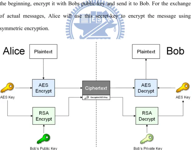
Digital Envelope is an application in which the sender seals the message in such a way that no one other than the intended recipient can open the sealed message. It uses both content-encryption algorithm (symmetric encryption) and key-encryption algorithm (asymmetric encryption)[32].
Figure 2.16 showed Digital Envelope architecture. AES symmetric encryption algorithm is adopted as content-encryption algorithm and RSA asymmetric encryption algorithm is adopted as key-encryption algorithm. Alice encrypts the message
(Plaintext) with the key of content-encryption algorithm that Bob knows it, too. And encrypts the key with Bob’s public-key using key-encryption algorithm and sends the ciphertext and encrypted key to Bob. Since the encrypted key is encrypted with a public-key, it can be decrypted with complement key in the same key- pair, which is Bobs private-key and only Bob knows it. At the moment, the encrypted key can be decrypted and the ciphertext is decrypted as plaintext simultaneously. Even though eavesdropper (Eve) can eavesdrop the ciphertext that he won’t know what the actual message that is being sent is.
Since asymmetric encryption is slower to do (asymmetric encryption is about 1000 times slower than symmetric encryption), Alice will create a new secret-key in the beginning, encrypt it with Bobs public-key and send it to Bob. For the exchange of actual messages, Alice will use this secret-key to encrypt the message using symmetric encryption.
Digital Signature
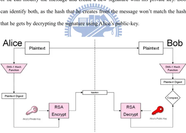
Figure 2.17 showed Digital Signature architecture. When Bob receives the plaintext-signature pair from Alice, he hashes the plaintext, with the same hash algorithm that Alice used, to generate a hash, and decrypts the Sign with Alice’s public-key to generate another hash. If both the hashes are same then the message came from Alice only and no one did alter the message in the transit.
If eavesdropper (Eve) attempts to forge Alice, he would capture the message-signature pair send by Alice and send a different message-signature pair to Bob. Eve can either send a modified message with the same signature that Alice sent, or he can modify the message and create a new signature with his private-key. Bob can identify both, as the hash that he creates from the message won’t match the hash that he gets by decrypting the signature using Alice’s public-key.
Combine Digital Envelope with Digital Signature
Figure 2.18 showed the architecture combined Digital Envelope with Digital Signature. This composite architecture combined the advantages of above secure architecture. It could achieve the following secure service standards: data confidentiality, data integrity, non-repudiation. Our secure network connection adopts this secure architecture.
2.6 System software design
2.6.1 Development environment
In our proposed system, the software is developed on C#. It is a type-safe object-oriented language that enables developers to build a variety of secure and robust applications that run on the .NET Framework.
C# programs run on the .NET Framework, an integral component of Windows that includes a virtual execution system called the common language runtime (CLR) and a unified set of class libraries. The CLR is the commercial implementation by Microsoft of the common language infrastructure (CLI), an international standard that is the basis for creating execution and development environments in which languages and libraries work together seamlessly[33].
Source code written in C# is compiled into an intermediate language (IL) that conforms to the CLI specification. The IL code and resources, such as bitmaps and strings, are stored on disk in an executable file called an assembly, typically with an extension of .exe or .dll. An assembly contains a manifest that provides information about the assembly's types, version, culture, and security requirements.
When the C# program is executed, the assembly is loaded into the CLR, which might take various actions based on the information in the manifest. Then, if the security requirements are met, the CLR performs just in time (JIT) compilation to convert the IL code to native machine instructions. The CLR also provides other services related to automatic garbage collection, exception handling, and resource management. Code that is executed by the CLR is sometimes referred to as "managed code," in contrast to "unmanaged code" which is compiled into native machine
language that targets a specific system. The following diagram illustrates the compile-time and run-time relationships of C# source code files, the .NET Framework class libraries, assemblies, and the CLR[33].
.NET Framework Platform architecture is shown as Figure 2.19[33].
Figure 2.19: .NET Framework Platform architecture[33].
2.6.2 MSP430 packet format
When bio-signal acquisition unit processed the bio-signal by MSP430, it will transmit the processed digital signal to PSG software (PSG Client) by Bluetooth module. These digital signals will pack to serial packets. MSP430 transmits packet format in one minute is shown as Figure 2.20. Per packet comprises Header section and Data section. Data section comprises n channel signal. The sampling rate is set as 256Hz in our device. Thus there are 256 continuous packets in one minute.
Figure 2.20: MSP430 transmits packet format in one minute.
Header
Header section takes 2 bytes up to use. There are some information hide from Header. That include sampling rate and how much channel of bio-signal acquisition unit. We fill “FF” in the first byte that to indicate this is Header section of the packet, because it’s impossible appear “FF” in other places. We fill information that is sampling rate and the number of channels in second byte. In Most Significant Bit (MSB) of the second byte (X), we fill in sampling rate, and fill in the number of channels in Least Significant Bit (LSB) of the second byte (Y). For example, if X is filled “9” indicate that the sampling rate is 256Hz (29); if Y is filled “2” indicate that the number of channels is 4 (22). Header information contrast table is shown as Figure 2.21.
Data
To suit with the filtered and amplified signal from front-end circuit, built in Analog to Digital Converter (ADC) of MSP430 was chosen to be an analog to digital converter. The ADC12 module supports fast, 12-bit analog-to-digital conversions. The module implements a 12-bit SAR core, sample select control, reference generator and a 16 word conversion-and-control buffer. Per converted channel digital signal is divided into two parts: MSB (6 bits) and LSB (6bits). We fill “01” in front of MSB and “10” in front of LSB respectively. Dividing process of converted digital signal is shown as Figure 2.22.
Figure 2.22: Dividing process of converted digital signal.
2.6.3 PSG Client design
The software of our proposed system is used modular concept for program design. There are seven modules in PSG Client: 1) Bluetooth Search Module, 2) Network Connect Module, 3) Subject Info Get Module, 4) Stream Input Module, 5) Display Module, 6) Encryption Module and 7) Data Record Module. According to the different demand, these modules could be reused easily.
Procedure of PSG Client
The operation procedure of PSG Client is shown as Figure 2.23. The process is listed below:
1. When the start button of PSG Client is turned on, Bluetooth Search Module will start to search nearby Bluetooth device, find out our Bio-signal Acquisition Unit and establish connection with the device.
2. Network Connect Module at this step will establish network connection with remote PSG Server and exchange each other’s public key.
3. Subject Info Get Module will get some information needed for EDF: local subject identification, local recording identification, start recording time and others parameter. These informations will be writed into EDF header.
4. Stream Input Module start to receive signal from Bluetooth stream, and write into the buffer.
5. When the buffer is full, Display Module will read datas from the buffer and draw the waveform on the waveform panel according these datas.
6. Encryption Module read data from the buffer. These datas will be processed by a serial of encryption function
7. Network Connect Module will transmit the encrypted data to PSG Server.
8. Data Record Module will read data from the buffer, and write data into EDF and text file respectively.
9. When the stop button is pressed, Data Record Module at this step will get the end recording time and update the EDF header.


![Table 2.1: Common band of EEG [16]](https://thumb-ap.123doks.com/thumbv2/9libinfo/8594935.189914/24.892.215.678.516.748/table-common-band-of-eeg.webp)
![Figure 2.7: A single modified ECG Lead II use torso electrode placement[18].](https://thumb-ap.123doks.com/thumbv2/9libinfo/8594935.189914/27.892.367.532.247.449/figure-single-modified-ecg-lead-torso-electrode-placement.webp)
![Table 2.2: Detailed digital format of the EDF header record[15].](https://thumb-ap.123doks.com/thumbv2/9libinfo/8594935.189914/32.892.132.749.160.1113/table-detailed-digital-format-edf-header-record.webp)
![Table 2.3: Summary of functions provided by the Berkeley sockets API library.[20]](https://thumb-ap.123doks.com/thumbv2/9libinfo/8594935.189914/34.892.129.765.149.1073/table-summary-functions-provided-berkeley-sockets-api-library.webp)
![Figure 2.14: The AddRoundKey step diagram[27].](https://thumb-ap.123doks.com/thumbv2/9libinfo/8594935.189914/45.892.164.645.234.700/figure-the-addroundkey-step-diagram.webp)