行政院國家科學委員會專題研究計畫 成果報告
子計畫六:多點視訊會議技術之研究(II)
計畫類別: 整合型計畫 計畫編號: NSC93-2219-E-009-022- 執行期間: 93 年 08 月 01 日至 94 年 07 月 31 日 執行單位: 國立交通大學電子工程學系暨電子研究所 計畫主持人: 林大衛 計畫參與人員: 詹益鎬、蔡鎮宇、簡志凱、蔡崇諺、吳和璋 報告類型: 完整報告 處理方式: 本計畫可公開查詢中 華 民 國 94 年 10 月 17 日
行政院國家科學委員會補助專題研究計畫成果報告
多點視訊會議技術之研究
(II)
Research in Multipoint Videoconferencing Technologies 計畫編號:NSC 93-2219-E-009-022 執行期限:93 年 8 月 1 日至 94 年 7 月 31 日 主持人:林大衛 交通大學電子工程學系 教授 計畫參與人員:詹益鎬、蔡鎮宇、簡志凱、蔡崇諺、吳和璋 交通大學電子工程學系 研究生
摘要
近年來,桌上型視訊會議技術已愈趨實用與可即。然而目前一般的系統仍不具有近 似當面開會的視聽感覺。本計畫主旨在研究分散式桌上型多點視訊會議技術,其中特 別著重視訊的處理,但也探討系統的整合。我們擬想中的系統,是在每個會議端點的 電腦螢幕上顯示一個虛擬的會議室場景,其中呈現所有其他端點與會人員的合成影 像。為此,每一端點需先將本地輸入視訊加以分割,取出與會者影像予以編碼,然後 併同聲訊傳到其他端點。每一端點也需將所有接收到的視訊及聲訊予以解碼及合成。 本計畫之研究係建構在MPEG-4 規範的基礎上,採用個人電腦為實現平台。其中之研 究子題可分四大組:會議系統、網路傳輸、傳送視訊處理、與接收視訊處理。本計畫 原定以三年時間進行研究。本報告係針對第二年之研究,其中著重視訊分割技術、傳 送端系統整合技術、及接收端系統整合技術。在視訊分割方面,我們提出了一些演算 法。在傳送端系統整合方面,我們將過去已實現的視訊分割法、加速後的MPEG-4 視 訊編碼程式、一個MPEG-4 聲訊編碼程式、以及一個 RTP 網路傳輸程式,在個人電腦 上加以整合,形成了一個傳送端系統的雛型。在接收端系統整合方面,我們則將一個 RTP 網路傳輸程式、一個 MPEG-4 視訊解碼程式、以及一個 MPEG-4 聲訊解碼程式, 在個人電腦上加以整合,並設計了一個多視訊結合的方法,將以上組合成了一個接收 端系統的雛型。 關鍵詞:MPEG-4 視訊編碼、視訊分割、視訊合成、多點視訊會議、視訊會議系統整 合Abstract
Desktop videoconferencing is becoming more practical and accessible in recent years. But typical systems today still lack the look and feel of a nearly face-to-face conference. The purpose of this project is to research into technologies for distributed desktop multipoint videoconferencing, wherein we especially emphasize the processing of video signals but also consider system integration. Our envisioned system is such that the computer screen of each conference terminal will show a virtual conference room scene synthesized from the images of the conferees at all other terminals. For this, each terminal will first need to segment the local input video to extract the image of the local conferee, encode it, and transmit it to the other terminals along with audio. Each terminal will also need to decode all the received videos and audios and form a composition. The research is conducted based on the MPEG-4 specifications, utilizing personal computers (PCs) as the realization platform. Subjects in this research can be divided into four major groups: conferencing system, network transport, transmitter video processing, and receiver video processing. The originally intended period of research is three years. This report is concerned with research done in year two, in which we have emphasized techniques for video segmentation, transmitter system integration, and receiver system integration. In video segmentation, we proposed several algorithms. In transmitter system integration, we implemented a rudimentary transmitter-end system by integrating a previously realized video segmentation method, an accelerated MPEG-4 video encoding program, an MPEG-4 audio encoding program, and an RTP network transport program on a PC. And in receiver system integration, we integrated an RTP network transport program, an MPEG-4 video decoding program, and an MPEG-4 audio decoding algorithm on a PC. Further, we designed a method to compose multiple videos, and put the above together into a rudimentary receiver-end system.
Keywords: MPEG-4 Video Coding, Video Segmentation, Video Composition, Multipoint
目錄
Table of Contents
一、計畫緣由與目的... 1
二、視訊分割演算法之進一步研究與結果... 3
A. Introduction ... 3
B. Existing Methods... 3
C. Our Proposed Method 1... 4
D. Our Proposed Method 2 ... 7
三、傳送端系統整合技術之研究與成果... 8
A. Introduction ... 8
B. Video Signal Processing ... 8
C. Integration of the Transmitter System ... 10
D. Some Experimental Results... 11
E. Conclusion ... 12
四、接收端系統整合技術之研究與成果... 13
A. Introduction ... 13
B. Video Decoding and Composition... 13
C. Receiver System Integration... 15
D. Some Experimental Results... 17
E. Conclusion ... 17
五、參考文獻... 18
六、計畫成果自評... 21
一、計畫緣由與目的
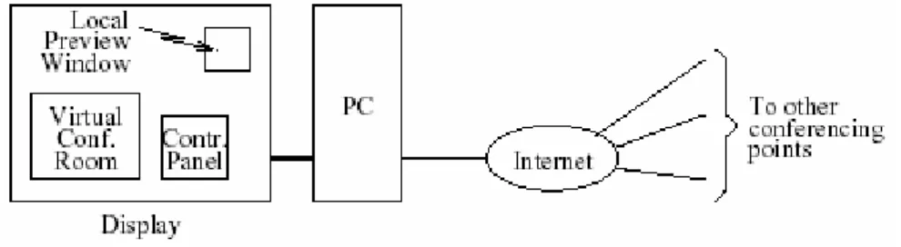
過去所謂視訊會議,通常是在特定的視訊會議室、使用特用的視訊會議設備來進 行。近年來,隨著視訊壓縮技術與數位積體電路的發展,透過個人電腦與網際網路來 在辦公室或家中打視訊電話或進行多點視訊會議已經不再是未來的夢想。許多軟體都 已能提供即時互動視訊通訊的功能。這種型態的互動式視訊通訊,有時被稱為桌上型 (desktop)視訊通訊。目前一般的桌上型多點視訊會議(multipoint videoconferencing)系 統,仍未提供近似於當面開會的視聽感覺。其實,即使是使用特定房間與設備的傳統 視訊會議,也未能達到近似於當面開會的特質。最近有一些研究,如[1]-[5]等,即在 探討視訊會議所呈現的畫面等等課題,以期能使視訊會議更具有趨近於當面開會的視 聽特質。若干研究中考慮將由數個會議端點所收到的視訊合成一個類似會議室的場 景。當然,在合成之前可能需要先將這些會議端點的與會人員的影像分割出來。其實 在virtual reality 領域,也有一些相關的研究,但重點未必針對面對面形式的視訊會議。 國內人士亦曾有相關之研究[6]-[9],但上述議題仍有不少待更深入探討之處。 本計畫主旨在研究桌上型多點視訊會議之相關技術,並建構一個實驗性之系統。本 計畫擬想中之視訊會議系統,可透過圖 1-1 說明之。圖中左方呈示之個人電腦(PC)及 螢幕(display),為每一會議點所使用之設備。螢幕顯示一個虛擬之會議室(virtual conference room),其中之視訊為所有其他會議點所傳來之與會人員視訊的一個合成 (composition)。會議室場景及各人的位置可考慮由一位與會者統一安排。螢幕上另有 二個視窗,即控制台(control panel)與本地視訊之預覽(local preview)。圖1-1:多點視訊會議系統架構示意圖
在稍早的研究中,我們發現 MPEG-4 標準中的若干規範相當適合本研究之所需。 例如:其視訊編碼部分容許將視訊分割後再編碼;其資料結構與合成部分定義了一個 相當有效率的BIFS (Binary Format for Scenes),並為場景製作(authoring)的方便,制定 了XMT (eXtensible MPEG Texual)檔案格式[10], [11];其網路傳輸部分定義了 DMIF (Delivery Multimedia Integration Framework)[10]等。故本計畫之研究原盼能完全基於 MPEG-4 之規範。但在後來的研究中,我們得知 DMIF 因過於複雜及乏人維護等因素, 後來未受業界所重視,而我們所能取得的DMIF 軟體也功能不全。此外,我們所能取 得的BIFS 與 XMT 相關軟體,功能上也有很大的限制。因此,在網路傳輸方面,我們 最後是使用 RTP(以下再進一步介紹),而在場景合成方面,則是自行設計其方法並撰 寫軟體。
本計畫之研究子題可分為四個群組,即會議系統、網路傳輸、傳送視訊處理、及接 收視訊處理,原定是以三年時間進行相關研究。本報告係針對第二年之研究,其中重 點在第三群組中的視訊分割技術,以及第一群組的傳送端系統整合技術與接收端系統 整合技術。在視訊分割方面,我們提出了一些演算法。在傳送端系統整合方面,我們 將過去已實現的視訊分割法、加速後的MPEG-4 視訊編碼程式、一個 MPEG-4 聲訊編 碼程式、以及一個RTP 網路傳輸程式,在個人電腦上加以整合,形成了一個傳送端系 統的雛型。在接收端系統整合方面,我們則將一個RTP 網路傳輸程式、一個 MPEG-4 視訊解碼程式、以及一個MPEG-4 聲訊解碼程式,在個人電腦上加以整合,並設計了 一個多視訊結合的方法,將以上組合成了一個接收端系統的雛型。 以下就分節簡述視訊分割、傳送端系統整合、以及接收端系統整合三方面的研究。 更詳細的討論見諸[12]-[14] (視訊分割)、[15]-[16] (傳送端系統整合)、及[17]-[18] (接收 端系統整合)。
二、視訊分割演算法之進一步研究與結果
1A. Introduction
Extraction of semantic video objects from natural video is a prerequisite for various content-based video applications. Here two key issues are the accurate identification of object boundaries and the required processing time. A common design of current object extraction algorithms is to first obtain, roughly, the location and the shape of the objects of interest via spatial and/or temporal analysis and then try to obtain a refined estimate of the object boundaries. In the spatial/temporal analysis, the algorithms may partition the video into regions showing homogeneity in certain features (such as intensity, color, and/or motion), or they may identify image areas showing heterogeneity (such as edges and/or changed areas) that may characterize object boundaries. In the refinement of object boundaries, some common approaches are contour evolution [19], [20], watershed analysis [21], [22], and edge linking [23]-[26]. We consider the edge-linking approach and propose several ways for efficient and accurate extraction of the object boundary.
In the edge-linking approach (as well as many other approaches), object boundaries are assumed to be situated at locations showing high intensity or color gradients. A popular method to find such locations is the Canny edge detector [27]. The need for edge linking arises because typical edge detectors often yield unconnected contours. Two problems that must be solved in edge linking are thus: 1) among all the edges that can be found in an image, which ones should be considered candidates for linking, and 2) among all the ways the candidate edges can be linked, what is the most proper way of linking (perhaps with slight modification of the edge locations if appropriate).
B. Existing Methods
Given a set of edges in a region, one common way to obtain a rough outline of the object is by orthogonal scans. In one technique [24], each row that contains edge pixels is considered. The space between the leftmost and the rightmost such pixels is filled in. Likewise, for each column that contains edge pixels, the space between the topmost and the bottommost such pixels is filled in. Then a rough object mask is obtained by ANDing the two pixel maps. In another technique [23], a row scan is performed as above. Then the result is subjected to a column scan, whose result is subjected to a second row scan. For convenience, we refer to these techniques as minimal scan and maximal scan, respectively.
Ideally, one would desire that the obtained mask boundary be close to the actual object boundary. However, whether this can be the case depends the object geometry. Some illustrative examples are given in [12].
1 This section is excerpted from Y.-H. Jan and D. W. Lin, “Edge-based morphological processing for efficient
and accurate video object extraction,” IEICE Trans. Inf. & Syst., vol. 88-D, no. 2, pp. 335-340, Feb. 2005, and Y.-H. Jan and D. W. Lin, “Automatic video segmentation with novel motion analysis and edge processing for accurate identification of object boundaries,” Int. J. Elec. Eng., vol. 12, no. 3, pp. 297-304, Aug. 2005.
After the orthogonal scans, several ways may be used to refine the object mask. Some employ morphological operations, and some employ a shortest-path algorithm to find and connect the boundary edges. The first way may yield an enlarged object contour beyond the actual object boundary (in addition to that due to orthogonal scans). The second way follows the edges better, and a favorite shortest-path algorithm is Dijkstra's algorithm [28]. However, if the orthogonal scans result in a greatly expanded object mask, then the shortest-path algorithm will need to sift out many pixels, which presents a complexity concern. Worse yet, if strong edges exist in the overgrown area of the mask and they are not identified and excluded for edge linking through some means, then these edges may be mistaken to be part of the object boundary.
C. Our Proposed Method 1
The proposal is mainly built on two relatively simple ideas: 1) to make more effective use of the object's known approximate location and shape to narrow the search area, and 2) to make more effective use of the detected edges interior to the search area.
To facilitate algorithm development and the following discussion, we assume use of change detection to roughly delineate the moving objects, but other techniques can also be employed. Change detection detects image areas that exhibit significant changes from one video frame to another. Normally, the result (termed “change detection mask” or CDM in short) will consist of pixels from both the moving objects and the background. Concerning edge detection, we employ the Canny edge detector.
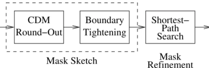
Our edge linking method consists of two stages: mask sketch and mask refinement. In the former we define the outer perimeter of the area that contains an object of interest, and in the latter we refine the estimated object boundary. They are discussed in separate subsections below. The overall procedure is illustrated in Fig. 2-1.
CDM Round−Out Boundary Tightening Mask Sketch Shortest− Path Search RefinementMask
Fig. 2-1: The first proposed method of video segmentation.
1. Mask Sketch
We illustrate the procedure using the arbitrary CDM example shown in Fig. 2-2(a), where pixels in the CDM are marked in gray.
To start, we round out the CDM to obtain a solid region. In addition to defining the maximum support of the object, this step also serves two functions. First, by this we make the edges interior to the CDM, but not part of it, also available for subsequent edge-based
processing. And secondly, we stop one- and two-pixel wide “cracks” in the CDM. More than one way exists to obtain the same result. One of them is described in [21]. To conserve space, we omit the details here. For the arbitrary CDM example of Fig. 2-2(a), we obtain Fig. 2-2(b) as the result.
(a) (b) (c)
(d) (e) (f) Fig. 2-2: Arbitrary example illustrating the proposed algorithm. (a) CDM. (b) Result of CDM round-out. (c) Result of CDM round-out with edge pixels therein marked in black. (d) Result of segmental row scans. (e) Result of segmental column scans. (f) Result of boundary tightening with edge pixels in the mask marked in black and other pixels in gray.
Next, we tighten the boundary of the rounded CDM by working with the edge pixels therein. Note that each row of pixels in the rounded CDM may consist of more than one connected segment, and likewise each column. We do “segmental orthogonal scans” as follows. First, for each connected horizontal segment that contains two or more edge pixels, we connect the furthest two of them. Then we regard the boundary pixels in the result as virtual edge pixels and, for each connected segment in each column of the rounded CDM, we connect the two furthest edge pixels. This completes the boundary tightening step. For the above example, let the edge pixels in the rounded CDM be as shown in black in Fig. 2-2(c). Then the resulting pixel maps after segmental horizontal and vertical scans are as illustrated in Figs. 2-2(d) and (e), respectively. To further appreciate the effects of these scans, Fig. 2-2(f) shows the result again, with the edge pixels marked in black while the others in gray. Comparing it with Fig. 2-2(c), we see that the mask is indeed tightened to match the edge contours better. While the technique of orthogonal scans may look much like that in maximal scan, the segmental nature leads to a very different result.
2. Mask Refinement
Now that we have bounded the outer perimeter of the object, we proceed to refine the estimated object boundary. For this we employ Dijkstra's shortest-path algorithm to find and to link up the outermost edges in the boundary-tightened mask.
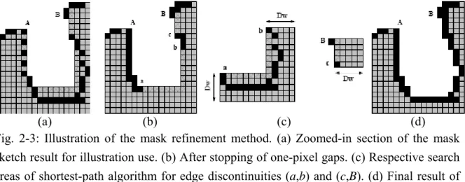
Figure 2-3 illustrates how our algorithm works using a section of the resulting mask shown in Fig. 2-2(f) from mask sketch. Consider edge linking between points A and B shown in Fig. 2-3(a), for example. The algorithm considers all edge pixels on the boundary
of the mask as belonging to the object boundary. First, all non-edge boundary pixels in the mask are identified. In Fig. 2-3(a), the non-edge boundary pixels between points A and B are marked by cross hatching. Next, we stop all edge gaps around the mask boundary that are only one pixel wide. This is done by examining each non-edge boundary pixel. If two of its orthogonal four-connected neighbors are edge pixels, it is declared to be an edge pixel. Fig. 2-3(b) shows the result for the example, where all pixels on the mask boundary (between A and B) that are now considered belonging to the object boundary are marked black. The others remain cross-hatched. For clarity, in this figure we omit the black marking of the edge pixels that are not on the mask boundary. Note that the above gap-stopping method is in effect a shortest-path algorithm over one-pixel gaps, but with lower complexity than normal Dijkstra algorithm. Regarding the example, we are now left with two edge discontinuities between A and B, defined by the pixel pairs (a,b) and (c,B), respectively.
(a) (b) (c) (d)
Fig. 2-3: Illustration of the mask refinement method. (a) Zoomed-in section of the mask sketch result for illustration use. (b) After stopping of one-pixel gaps. (c) Respective search areas of shortest-path algorithm for edge discontinuities (a,b) and (c,B). (d) Final result of edge linking between A and B.
The algorithm continues by considering separately each remaining edge discontinuity along the mask boundary. For each discontinuity, we search in the mask for the shortest path that bridges it, where each edge pixel in the mask is given a smaller equivalent length and each non-edge pixel a larger equivalent length. To control the computational complexity, we may limit the search area to a band around the mask's boundary. Let Dw be the bandwidth in
number of pixels. For example, Fig. 2-3(c) illustrates the two search areas for the edge discontinuities (a,b) and (c,B), respectively, with Dw = 5. After executing Dijkstra's
shortest-path algorithm over the two search areas separately, we obtain the final result shown in Fig. 2-3(d) for edge linking between A and B.
3. On Algorithm Complexity
The complexity of the above algorithm depends on the detailed organization of the operations involved. Nevertheless, we can see that a “mask sketch” as described above involves several passes over the CDM and its interior, each pass involving some simple logical operations on each pixel. Therefore, the complexity of mask sketch is on the order of
the size of the extracted object. The complexity of mask refinement depends on the total length of the edge discontinuities. A typical implementation of the Dijkstra algorithm has
O(n2) complexity, where n is the number of pixels in the search area. Thus the complexity
of mask refinement is at most O(L2Dw2) where L is the perimeter of the extracted object.
4. Some Experimental Results
Experiments show that the proposed method is efficient and performs well. Figure 2-4 shows some results from using two different values of Dw in mask refinement. For more
discussion on the efficiency and the performance of the method, see [12].
(a) (b)
Fig. 2-4: Result of mask refinement at different search bandwidths for a frame in the Mother-and-Daughter sequence. (a) Dw = 2. (b) Dw = 5.
D. Our Proposed Method 2
The second method that we propose will take some length to describe, hence we omit the details. The interested reader may refer to [13], which also presents some subjective and objective results. The method also takes the edge-linking approach, but in performing edge linking, it employs a heuristic scheme rather then Dijstra’s algorithm. This has the potential of a reduced computation time. It employs motion-compensated tracking of moving objects, where the motion estimation technique is novel and of low complexity. The overall algorithm structure is as shown in Fig. 2-5.
FRAME MEMORY DETECTIONCHANGE
EDGE FRAME n
TRACKING VALIDATIONBACKWARD INPUT VIDEO FORWARD FRAME n−1 DETECTION FRAME n−p VIDEO OBJECT EXTRACTION
Fig. 2-5: The second proposed method of video segmentation.
Experiments using a personal computer with 1.8-GHz Pentium CPU and an un-optimized program show that it only takes about 30-40 ms to segment a CIF frame. Hence the method is suitable for real-time desktop or portable videoconferencing applications.
三、傳送端系統整合技術之研究與成果
2A. Introduction
As mentioned above, we consider constructing a different kind of videoconference system in which the decoded conferee images are composed into one virtual scene. For this, a natural approach is to segment the source videos at their respective transmitter sites before encoding and let each receiver do the composition after decoding the received object videos. This section considers the design and implementation of a videoconference transmitter supporting the above application.
The architecture of our videoconference transmitter is illustrated in Fig. 3-1. It includes the following functionalities: video capture, video segmentation, MPEG-4 object-based video encoding, audio capture, audio encoding, and a network interface based on the Real-time Transport Protocol (RTP). In what follows, we first describe the two key video signal processing components, namely, video segmentation and video encoding. We then describe how all the system components are integrated. Finally, we present some experimental results before a short conclusion.
Fig. 3-1: Videoconference transmitter system.
B. Video Signal Processing
1. Video Segmentation
The purpose of video segmentation is to obtain the moving foreground (the conferees' image in videoconferencing) for encoding and transmission. Our segmentation method is modified and simplified from [29]. (The methods described in the last section may be employed in future revisions of the system.) It employs a “background subtraction” approach suitable for videos with largely stationary background. In essence, it tries to build a background image by analyzing some number of input video frames. Then it compares any subsequent input frame with the background image and declares the areas where the two differ significantly as the foreground.
2 This section is excerpted from C.-Y. Tsai, C.-K. Chien, and D. W. Lin, “A videoconference transmitter
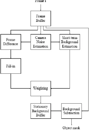
Fig. 3-2 shows a flowchart of the final algorithm. Briefly, it works as follows: Based on the estimated camera noise level, some thresholds are set so that interframe differences exceeding a certain level indicate, potentially, pixels belonging to moving objects. The “fill-in” and the “short-term background estimation” blocks are, respectively, functions to obtain tentative estimates of foreground and background image regions. They are then weighted to obtain the final background image as indicated.
Fig. 3-2: Flowchart of our video segmentation algorithm.
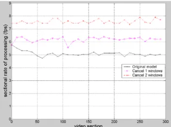
For system integration, the speed is a major concern. In our work, one item that comes as a surprise is the time taken to display the segmentation results in desktop windows of the PC. Fig. 3-3 shows the original graphical user interface (GUI) [29]. Besides a message window, it shows the input video, the object mask, and the stationary background buffer in separate windows. Display of the object mask and the stationary background buffer makes many calls to the SetPixel function provided by the Windows system, which is found to consume very much computing resource. Hence we allow the user not to show the object mask and the stationary background buffer to attain higher speed.
Fig. 3-4 shows the processing speed in debug mode with the modified GUI, employing a laptop PC with Intel Centrino Pentium M 1.5 GHz CPU, 512 MB DDR RAM, and running Microsoft Windows XP Professional Version 2002. Note that the processing speed increases significantly by eliminating one or two windows, which was quite unexpected. A more efficient way to display the segmentation results is being sought.
Fig. 3-3: The original GUI of the video segmentation system (from [29]).
Fig. 3-4: Processing speed in debug mode with modified user interface.
2. MPEG-4 Object Video Encoding
The object video encoder used in our system is based on the accelerated version of the public Microsoft MPEG-4 Video Reference Software as reported in [30]. The acceleration is achieved by algorithm modification (such as using less complex motion estimation methods) and by employing the MMX (multimedia extensions) co-processor that comes with the Intel CPU for repetitive and computation-intensive operations. The MMX co-processor uses the single instruction, multiple data (SIMD) technique. Different versions of it support parallel operations on 64- or 128-bit entities considered as multiple bytes, words, or longer data types.
Analysis of the accelerated software shows that the encoder complexity is now rather evenly spread over many functions. Hence no further acceleration of the encoder software is done in this work except to integrate it into the overall system.
C. Integration of the Transmitter System
integrate the components together.
For video capture, we make use of a free application software called AVICap from [31]. AVICap, by default, routes video and audio stream data from a capture window to a file named CAPTURE.AVI in the root directory of the current drive. We did some changes to sidestep file writing and reading [32]. The modification can result in significant gain in capturing speed. For example, experiments with one particular web camera show that the speed rises from about 11 fps to about 30 fps, which seems to be the limit of this particular web camera, whatever the model of the PC.
For video segmentation, after the simplification described previously, the segmentation algorithm itself does not constitute a bottleneck of the overall system. Nevertheless, we still make some effort in speeding up the most time-consuming operation using the MMX co-processor, which can speed up the algorithm by roughly 8%.
For the video encoder, we need to change its input from files to the segmented video, and its output also from a file to the RTP program input. The encoding mode used is the “Binary Shape Object Coding” mode, where a binary shape mask is used to define the location of the foreground video object.
For audio encoding, we use MCI (Media Control Interface) to capture the input audio in real-time, and use the FAAC software for audio encoding [33].
For network transport, we use RTP as mentioned before. RTP provides end-to-end network transport functions applicable to real-time data transmission, such as interactive audio and video, and hence is suitable for our application. It is typically run on top of UDP to make use of the latter's multiplexing and checksum services. RTP also supports multicasting, but this functionality is not used in our work. In fact, the RTP is composed of two parts: In addition to the “RTP” part that carries data with real-time characteristics, there is the RTP control protocol (RTCP) that monitors the quality of service and conveys information about the participants in a session. The latter aspect of RTCP is useful for “loosely controlled” sessions where there is no explicit membership control. We use the JRTPLib software, a public source written in C++, to implement the RTP transport interface [34]. The software is such that the user only needs to provide the payload data to be sent, and the software will give the user access to incoming RTP and RTCP data.
D. Some Experimental Results
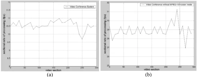
Fig. 3-5(a) shows the processing speed of the overall transmitter system including all the elements shown in Fig. 3-1, using the PC described earlier. The average processing speed is approximately 10.7 CIF (352 x 288) fps. Fig. 3-6 shows a breakdown of the complexity by functions as obtained by Intel's VTune performance analyzer.
The complexity analysis shows that the system component limiting the overall speed is the MPEG-4 video encoder. Video capture, audio capture, audio encoding, RTP, and even the video segmentation all contribute to a relatively minor amount only. This can be seen more clearly from Fig. 3-5(b), which shows the processing speed without the video encoder.
The average speed is close to 29 fps, which is only somewhat lower than the 30 fps with video capture alone. But from Fig. 3-6, there are no clearly identifiable bottleneck functions in the MPEG-4 video encoder. Hence further speedup of the system may entail very close look at and fine-tuning of many video encoder functions.
(a) (b) Fig. 3-5: Processing speed. (a) Overall system. (b) System without MPEG-4 video
encoding.
Fig. 3-6: Complexity breakdown of the overall system.
E. Conclusion
We developed a PC-based videoconference transmitter that supports object-based video encoding with real-time video segmentation. Experiments employing a PC with Intel Centrino Pentium M 1.5 GHz CPU, 512 MB of DDR RAM, and running Microsoft Windows XP Professional Version 2002 showed that the not yet fully optimized program could deliver a rate of 10.7 CIF fps. Further enhancement of the system in speed and robustness is planned.
四、接收端系統整合技術之研究與成果
3A. Introduction
To reiterate, we consider constructing a different kind of system in which the decoded videos are composed into a virtual conference room scene. For this, a natural and simplest approach is to segment and encode the source videos separately at their respective transmitter sites, and let each receiver decode all received videos and compose and display the result. The MPEG-4 standards, with their provision for object-based video coding, appear naturally fitting for this use.
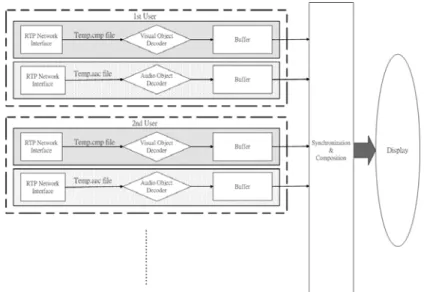
In this section, we discuss the design and implementation of the receiver on a personal computer (PC), in software. There are four major components in the receiver: the network interface, the video decoder, the audio decoder, and the composition unit, as illustrated in Fig. 4-1. As explained previously, we employ the Real-time Transport Protocol (RTP) for the network interface and develop our own composition method, leaving the video and the audio encoded and decoded according to MPEG-4 specifications.
Fig. 4-1: Structure of the proposed videoconference receiver.
In what follows, we first discuss how we decode and compose multiple videos into one scene. Then we describe the integration of the receiver system. Finally, we present some experimental results before a brief conclusion.
B. Video Decoding and Composition
As said previously, we develop a simple video composition method in this work. This involves not only composition of multiple videos into one scene, but also synchronization among the multiple decoders. For simplicity, we assume that all videos have the same frame
3 This section is excerpted from C.-K. Chien, C.-Y. Tsai, and D. W. Lin, “A multipoint videoconference
rate and relegate the situation with disparate frame rates to potential future research. Note, however, that in the latter situation, we may consider skipping some frames in the videos with higher frame rates, which should not cause much problem in videoconferencing when the frame rates are high enough. In this case, only minor modifications are needed in the present program.
We first consider the situation with two videos and two decoders. The two decoders are placed in two threads on the PC. To synchronize the decoded videos, for each frame we let the first decoder wait until the second decoder completes. Then it starts working on the next frame. Composition and display of the videos are done in the second thread. Figure 4-2 shows the temporal relation between the two decoders.
Fig. 4-2: Relation between the two decoders in time domain.
To compose the two images decoded by the two decoders, note that there are several possible spatial relations between them, as illustrated in Fig.4-3. Case 0 is where there is no overlap between the two images. If there is some overlap between the two images, we let the first image occlude the second in the overlapped area. In the integrated receiver system, we let the user determine and specify where each decoded video is to be placed in the display window.
Fig. 4-3: Different spatial relations between two images. (a) Case 0, no overlap. (b)-(e) Cases 1-4, respectively, with overlaps.
Now consider the situation with four (or three) videos. Figure 4-4 explains our method of composition. The outputs of the decoders are composed together in a binary tree fashion.
The “padding” referred in the figure is to pad the image into the form of a box for display purpose. For more videos, we simply extend the “composition tree.” In any case, it is always the highest-indexed video that controls the composition and display operation.
Fig. 4-4: Composition of four (or three) videos.
C. Receiver System Integration
1. Overall System Structure
Figure 4-5 shows how the integrated receiver program works. The GUI block creates a window and the user can input the ports and the positions of the different videos. Since there may be multiple video and audio streams to be handled, we put the decoders in multiple threads, which lets the operating system handle their scheduling.
So, after the user has specified the ports and the positions of the videos, the system creates the decoder threads. It also obtains information on which decoders are active at present, so as to determine the highest-indexed video decoder and pass the control responsibility (including video composition and display) to it. Now the video and the audio decoders can begin their work in decoding the data received through the RTP network interface. The composed video is displayed in a window and the composed audio is played.
2. The RTP Network Interface
As in the transmitter, we employ the JRTPLIB 3.1.0 software for the network interface. Two important parameters that need to be set for each session are the timestamp and the portbase. The timestamp parameter is set to 1 section per second for a video stream and to 1 section per 4 seconds for an audio stream. (These parameter values are somewhat inappropriate for real-time applications, but are chosen based on experience for smooth running of the program. Further work is needed to determine the underlying problem and potential solution.) For the portbase, since each transmitter sends two streams (video and audio), the video stream uses a user-specified port number and the audio stream uses that number plus 100.
In our system, after the setting of these parameters, we put the receiving of the RTP packets in a main loop. For some reason yet unclear, the software would lose the first two packets and receive the third and later packets successfully.
3. Video Decoding and Display
Our video decoder is from the public Microsoft MPEG-4 Video Reference Software. To integrate the video decoder into the overall system, we modify the original decoder program into a function called MPEG4VDecoder and give it two parameters: handle (of the display window) and thread index. The handle can give the decoder some information to control the window and display the video stream.
To display the video, we convert the decoder output from the original 4:2:0 format to the 4:4:4 format. Then we calculate the RGB values of each pixel from the luminance and the chrominance values. And then we use the SetPixelV function provided by the Windows SDK library to display the RGB values pixel by pixel. Experience shows that the SetPixelV function is very slow and can significantly slow down the overall speed of the receiver system. Hence, to reduce its use, instead of using it on all pixels in the display window, we only use it to update the pixels in the object areas of two successive frames.
3. Audio Decoding and Composition
For audio decoding, we use the Freeware Audio Decoder (FAAD2) [33]. We only make use of the MAIN profile. After decoding the audio stream, the result is saved as a temporal audio file in the WAV format. The Media Control Interface (MCI), a high level open interface, is used to play the audio. Since each audio section is four seconds, the decoder
would wait for that long as the decoder output is played by the MCI.
For audio composition, two intuitive methods are (1) to sum all audio streams and (2) to play only one stream. The first method suffers an overflow problem which can be solved by proper scaling. This is left to potential future work. For simplicity in the final system we only play the audio from the first transmitter site.
D. Some Experimental Results
For convenience, for the video part we use the CIF test sequence Bream with its associated binary shape information. Multiple instances of the sequence are considered separate video transmissions. Figure 4-6 shows some typical composed scenes with two videos. We noted previously that the SetPixelV (and SetPixel) function was slow. Time analysis shows that image display alone can take over 70% of the overall processing time. Hence, unless we can find more efficient ways to set the display pixels, we should minimize the use of the time-consuming SetPixelV and SetPixel functions.
Fig. 4-6: Some typical composed scenes with two videos.
Experiments with the fully integrated receiver system show that the processing speed is approximately 11.2 fps with one video, 5.2 fps with two videos, and 3.6 fps with three videos (all Bream). Hence it is approximately reciprocal to the number of videos.
E. Conclusion
We considered the design and implementation of a novel type of software-based multipoint videoconference receiver on a PC, where some distinguishing features were the use of MPEG-4 object-based coding and the composition of decoded videos into one scene. Further enhancement of the system in speed and robustness is considered.
五、參考文獻
[1] M. E. Lukacs and D. G. Boyer, “A universal broadband multipoint teleconferencing service for the 21st century,” IEEE Commun. Mag., vol. 33, no. 11, pp. 36-43, Nov. 1995.
[2] D. G. Boyer, M. E. Lukacs, and M. Mills, “The personal presence system experimental research prototype,” in IEEE Int. Conf. Commun. Conf. Rec., pp. 1112-1116, 1996. [3] O. Schreer, M. Karl, and P. Kauff, “A Trimedia based multi-processor system using
PCI technology for immersive videoconference terminals,” in Int. Conf. Digital Signal
Processing, pp. 289-293, 2002.
[4] MoMuSys, “MoMuSys final report,” Mar. 2001. Available from http://www.tnt.uni-hannover.de/project/eu/momusys.
[5] O. Schreer, H. Fuchs, W. IJsselsteijn, and H. Yasuda, eds., Special Issue on Immersive
Telecommunications, IEEE Trans. Circuits Syst. Video Technol., vol. 14, no. 3, Mar.
2004.
[6] Y.-J. Chang, C.-C. Chen, J.-C. Chou, and Y.-C. Chen, “Implementation of a virtual chat room for multimedia communications,” in IEEE Workshop Multimedia Signal
Processing, pp. 599-604, 1999.
[7] Y.-J. Chang, C.-C. Chen, J.-C. Chou, and Y.-C. Chen, “Virual Talk: a model-based virtual phone using layered audio-visual integration,” in IEEE Int. Conf. Multimedia
Expo, pp. 415-418, 2000.
[8] C.-W. Lin, W.-H. Wang, M.-T. Sun, and J.-N. Hwang, “Implementation of H.323 multipoint video conference systems with personal presence control,” in IEEE Int.
Conf. Consumer Electron. Digest of Tech. Papers, pp. 108-109, 2000.
[9] C.-W. Lin, Y.-J. Chang, Y.-C. Chen, and M.-T. Sun, “Implementation of a realtime object-based virtual meeting system,” in IEEE Int. Conf. Multimedia Expo, pp. 565-568, 2001.
[10] S. Battista, F. Casalino, and C. Lande, “MPEG-4: a multimedia standard for the third millenniem,” in two parts, IEEE Multimedia, vol. 6, no. 4, pp. 74-83, Oct.-Dec. 1999, and vol. 7, no. 1, pp. 76-84, Jan.-Mar. 2000.
[11] M. Bourges-Sevenier and E. S. Jang, “An introduction to the MPEG-4 Animation Framework eXtension,” IEEE Trans. Circuits Syst. Video Technol., vol. 14, no. 7, pp. 928-936, July 2004.
[12] Y.-H. Jan and D. W. Lin, “Edge-based morphological processing for efficient and accurate video object extraction,” IEICE Trans. Inf. & Syst., vol. 88-D, no. 2, pp. 335-340, Feb. 2005.
[13] Y.-H. Jan and D. W. Lin, “Automatic video segmentation with novel motion analysis and edge processing for accurate identification of object boundaries,” Int. J. Elec. Eng., vol. 12, no. 3, pp. 297-304, Aug. 2005.
[14] Y.-H. Jan, “Research in video segmentation techniques for object-oriented applications,” Ph.D. dissertation, Dept. Electronics Engineering, National Chiao Tung University, Hsinchu, Taiwan, R.O.C., May 2005.
[15] C.-Y. Tsai, C.-K. Chien, and D. W. Lin, “A videoconference transmitter supporting object-based video encoding with real-time video segmentation,” to appear in Proc.
Workshop Consumer Electronics Signal Processing, Nov. 2005.
[16] C.-Y. Tsai, “Integration of videoconference transmitter with MPEG-4 object-based video encoding,” M.S. thesis, Dept. Electronics Engineering, National Chiao Tung University, Hsinchu, Taiwan, R.O.C., June 2005.
[17] C.-K. Chien, C.-Y. Tsai, and D. W. Lin, “A multipoint videoconference receiver based on MPEG-4 object video,” to appear in Proc. Int. Symp. Commun., Nov. 2005.
[18] C.-K. Chien, “A multipoint videoconference receiver for MPEG-4 object-based video,” M.S. thesis, Dept. Electronics Engineering, National Chiao Tung University, Hsinchu, Taiwan, R.O.C., June 2005.
[19] S. Sun, D. R. Haynor, and Y. Kin, “Semiautomatic video object segmentation using VSnakes,” IEEE Trans. Circuits Syst. Video Technol., vol. 13, no. 1, pp. 75-82, Jan. 2003.
[20] A.-R. Mansouri and J. Konrad, “Multiple motion segmentation with level sets,” IEEE
Trans. Image Processing, vol. 12, no. 2, pp. 201-220, Feb. 2003.
[21] D. Wang, “Unsupervised video segmentation based on watersheds and temporal tracking,” IEEE Trans. Circuits Syst. Video Technol., vol. 8, no. 5, pp. 539-546, Sep. 1998.
[22] S.-Y. Chien, Y.-W. Huang, and L.-G. Chen, “Predictive watershed: a fast watershed algorithm for video segmentation,” IEEE Trans. Circuits Syst. Video Technol., vol. 13, no. 5, pp. 453-461, May 2003.
[23] T. Meier and K. N. Ngan, “Video segmentation for content-based coding,” IEEE Trans.
Circuits Syst. Video Technol., vol. 9, no. 8, pp. 1190-1203, Dec. 1999.
[24] C. Kim and J. N. Hwang, “Fast and automatic video object segmentation and tracking for content-based applications,” IEEE Trans. Circuits Syst. Video Technol., vol. 12, no. 2, pp. 122-129, Feb. 2002.
[25] L. Atzori, D. D. Giusto, and C. Perra, “A novel block-based video segmentation algorithm,” in IEEE Int. Conf. Multimedia Expo, pp. 653-656, 2001.
[26] H. Luo and A. Eleftheriadis, “Rubberband: an improved graph search algorithm for interactive object segmentation,” in Proc. IEEE Int. Conf. Image Processing, vol. 1, pp. 101-104, 2002.
[27] J. Canny, “A computational approach to edge detection,” IEEE Trans. Pattern Anal.
Machine Intell., vol. 8, no. 6, pp. 679-698, Nov. 1986.
[28] E. W. Dijkstra, “A note on two problems in connexion with graphs,” Numer. Math., vol. 1, pp. 269-271, 1959.
[29] Y.-H. Lin, “Real-time video segmentation based on background modeling for videoconferencing,” M.S. thesis, Dept. of Electronics Engineering, National Chaio Tung University, Hsinchu, Taiwan, R.O.C., June 2004.
[30] M.-Y. Liu, “Real-time implementation of MPEG-4 video encoder using SIMD-enhanced Intel processor,” M.S. thesis, Degree Program of Electrical Engineering and Computer Science, National Chaio Tung University, Hsinchu, Taiwan, R.O.C., July 2004.
[31] “VidCap: Full-featured video capture application,” http://msdn.microsoft.com/library/devprods/vs6/visualc/vcsample/vcsmpvidcap.htm.
[32] “Capture without using disk storage,” http://msdn.microsoft.com/library/default.asp?url=/library/en-us/multimed/htm/_win32
_capture_without_using_disk_storage.asp.
[33] “AudioCoding.com,” http://www.audiocoding.com/.
六、計畫成果自評
研究內容與原計畫相符程度:符合計畫主題,達成之主要成果包括:視訊分割技術 之進一步研究成果、傳送端系統整合之技術與簡單雛型、及接收端系統整合之技術與 簡單雛型。 達成預期目標情況:本子計畫達成之貢獻形式,含先前技術之改進、技術水準之提 升、實驗系統之建立、人才培育。 成果之學術與應用價值等:視訊分割方面之若干成果已發表為期刊論文。多點視訊 會議傳送端系統與接收端系統整合之研究成果亦已將發表於國內會議,並可供相關業 界研發之參考。以上各方面研究之經驗與成果亦可成為我們後續相關研究的參考。 綜合評估:本計畫獲得一些具有學術與應用價值的成果,並達人才培育之效。成效 良好。可供推廣之研發成果資料表
□ 可申請專利 ■ 可技術移轉 日期:94 年 7 月 31 日國科會補助計畫
計畫名稱:多點視訊會議技術之研究(II) 計畫主持人:林大衛 計畫編號:NSC 93-2219-E-009-022 學門領域:電信國家型計畫技術/創作名稱
以物件編碼為基礎之新型多點網路視訊會議技術與雛型發明人/創作人
蔡鎮宇、簡志凱、林大衛 中文:在傳送端將輸入之視訊加以分割,取出與會人的影像,將其 與聲訊個別以MPEG-4 物件視訊及聲訊編碼法加以編碼,透過 RTP 傳出。在接收端透過 RTP 機制接收其他各會議端點傳來的資訊, 做視訊與聲訊解碼,然後將視訊合成一個畫面顯示,而聲訊則選用 其中之一(或全體相加)播放。技術說明
英文:At the transmitter, segment the input video and extract the conferee image. Encode it and the audio using MPEG-4 object-based video coding and audio coding, respectively. Transmit the result by RTP. At the receiver, employ RTP to receive the information from all other conference terminals and perform video and audio decoding. Then compose the videos into one scene for display, and play one chosen audio (or the sum of all audios).