國 立 交 通 大 學
光 電 工 程 研 究 所
碩士論文
在單一波長上同步產生及傳輸
基頻與高頻訊號
Simultaneous Generation and Transmission of
Baseband and RF Signals on a Single
Wavelength
研
究
生 : 彭 晟 峰
指 導 教 授 : 陳 智 弘 老師
在單一波長上同步產生及傳輸
基頻與高頻訊號
Simultaneous Generation and Transmission of
Baseband and RF Signals on a Single
Wavelength
研 究 生 :彭晟峰
Student : Cheng-Feng Peng
指導教授 :陳智弘 老師
Advisor : Associate Prof. Jyehong Chen
國 立 交 通 大 學
光 電 工 程 研 究 所
碩 士 論 文
A Thesis
Submitted to Institute of Electro-Optical Engineering
College of Electrical Engineering and Computer Science
National Chiao Tung University
In Partial Fulfillment of the Requirements
For the Degree of
Master
In
Institute of Electro-Optical Engineering
June 2007
Hsinchu, Taiwan, Republic of China
致謝
Acknowledgements
一轉眼兩年的碩士生涯終於要畫上句點了,很感謝在許多人的幫助下才能完 成這篇碩士論文。 首先要感謝我的指導教授陳智弘老師帶領我進入光通訊這個博大森淵的領 域,使我對光通訊有更進一步的了解,同時在他亦師亦友的教導下,學習到很多 待人接物和求學應有的態度。另外特別要感謝林俊廷學長,在他細心和不厭其煩 的教導下,以及實驗期間不斷容忍我所犯的過錯給我鼓勵。如果沒有林俊廷學長 的耐心指導相信今天這篇論文無法順利誕生。還有魏嘉建學長、蔡昇佑學長、林 澤雨學姊,以及五樓的其他學長們,無論是在學業及論文的研究,軟硬體的使用 上也給了我許多幫助,常常很多遇到的難題在請教他們之後都能迎刃而解。 還有陪伴我度過這兩年碩士生涯的同學,正哥、建和、俊臻,不論是在課業 上,還是日常生活上,都幫我度過了許多的難關。還有一年級的眾學弟,因為有 了你們,光電聯誼盃的歡樂,聚餐時的八卦等,都將是難忘的回憶。 最後,我要感謝我的家人,分享著我碩士生涯的點滴,並在背後默默地支持。 要感謝的人實在太多,總之,感謝大家!在單一波長上同步產生及傳輸
基頻與高頻訊號
學生:彭晟峰 指導教授 : 陳智弘 老師
國立交通大學光電工程研究所碩士班
摘要
混合訊號存取網路是整合光纖到家系統和光纖傳送無線電訊號系統在共享 的單一分散式基礎架構,它有希望成為未來的多功能服務存取網路。最重要的是 它能在單一波長上同步傳輸光纖到家系統和光纖傳送無線電訊號系統中的高頻 和基頻訊號。 本論文以實驗的方式展示了如何使用一顆外調式整合調變器在單一波長上 同步產生與傳輸基頻訊號及高頻訊號。此混合訊號是使用標準的單模光纖作傳 輸,而且不會遇到因為光纖色散導致訊號週期性地時強時弱的問題,也沒有遇到 基頻訊號與高頻訊號互相干擾的問題。Simultaneous Generation and Transmission
of Baseband and RF Signals on a Single
Wavelength
Student:Cheng-Feng Peng Advisor : Dr. Jyehong Chen
Institute of Electro-Optical Engineering
National Chiao-Tung University
Abstract
Hybrid optical access networks, integrating fiber-to-the-home (FTTH) and radio-over-fiber (RoF) systems that share a single distributed infrastructure, are promising for future multi-service access networks. Of priority concern is to enable RoF and FTTH systems to transmit simultaneously both RF and baseband (BB) signals on a single wavelength over a single fiber.
This study experimentally demonstrates simultaneous generation and transmission of a baseband (BB) signal and a RF signal on a single wavelength, using one external integrated modulator. The hybrid signals transmitted over standard single mode fiber (SSMF) do not suffer from periodic performance fading due to fiber dispersion and interference between BB and RF signals.
C
ONTENTSAcknowledgements
………...……….. iChinese Abstract
... iiEnglish Abstract
... iiiContents
... ivList of Figures
... viList of Tables
... ixCHAPTER 1
Introduction
1.1 Basic structure of radio-over-fiber (RoF) system…...11.2 Motivation……….…...3
CHAPTER 2
The new architecture of hybrid optical access network 2.1 Preface……..………...42.2 Mach-Zehnder Modulator (MZM)...4
2.3 External integrated modulator ...………….5
2.4 The architecture of RoF system………...6
2.4.1 Optical transmitter...6
2.4.2 Optical microwave/mm-wave generations based on LiNbO3 MZM...7
2.4.3 Communication channel...7
2.4.4 Demodulation of optical microwave/mm-wave signal……..………...9
2.5 The new model of hybrid optical access network………..………...10
CHAPTER 3
Generation of RF Signal Using Only One
Single-Electrode Mach-Zehnder Modulator
3.1 Conventional experiment...123.2 Experimental components parameter...12 3.3 Experimental setup and results using a DD-MZM based on DSBCS modulation
………..………. 13
3.3.1 Experimental setup...13
3.3.2 Optimal condition for RF signal...14
3.3.3 Transmission results...17
3.4 Experimental setup and results using a SD-MZM based on DSBCS modulation ...18
3.5 Discussions………...19
CHAPTER 4
Hybrid Optical Access Network Integrating
Fiber-to-the-home and Radio-over-fiber Systems
4.1 Preface………204.2 Experimental components parameter……….21
4.3 Experimental setup and results of hybrid signal which RF signal using DSBCS Modulation……….21
4.3.1 Experimental setup………21
4.3.2 Optimal condition for RF signal………23
4.3.3 Transmission condition for hybrid signal………..27
4.3.4 Transmission results of hybrid signal………29
4.3.5 Discussion……….30
4.4 Experimental setup and results of hybrid signal which RF signal using DSB Modulation……….31
4.4.1 Experimental setup………31
4.4.2 Optimal condition for RF signal………32
4.4.3 Transmission condition for hybrid signal………..34
4.4.4 Transmission results of hybrid signal………36
4.4.5 Discussion……….37
L
IST OFF
IGURESFig. 1-1 Basic structure of microwave/millimeter-wave wireless system Fig. 1-2 Basic structure of RoF system
Fig. 2-1 The Mach-Zehnder modulator has two intensity trimmers on the arms Fig. 2-2 Structure of external integrated modulator
Fig. 2-3 (a) and (b) are two schemes of transmitter and (c) is duty cycle of subcarrier biased at different points in the transfer function.
Fig. 2-4 Optical microwave/mm-wave modulation scheme by using MZM Fig. 2-5 The model of communication channel in a RoF system
Fig. 2-6 The model of receiver in a RoF system Fig. 2-7 The model of RoF system
Fig. 2-8 The model of BB signal generation
Fig. 2-9 The model of hybrid optical access network. (a) use DSBCS scheme to generate RF signal (b) use DSB scheme to generate RF signal.
Fig. 3-1 Experimental setup for optical microwave generation based on DSBCS modulation scheme using one MZM.
Fig. 3-2 BER curves (a) and power penalty (b) of down-converted signal for different MI.
Fig. 3-3 BER curves (a) and power penalty (b) of BB signal for different MI.
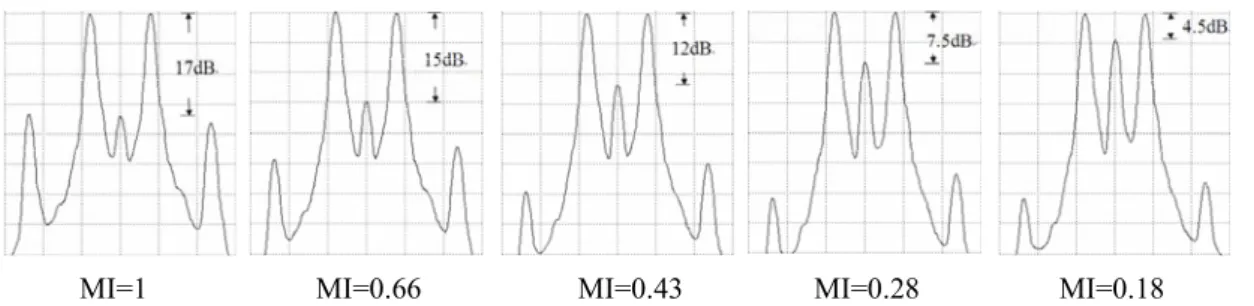
Fig. 3-4 Duty cycles of optical microwaves based on DSBCS modulation. The optical microwave power is 1dBm. The optical power scale is 0.8 mW/div and the time scale is 20 ps/div.
Fig. 3-5 The OCSR of optical microwaves based on DSBCS modulation. The resolution is 0.01nm.
Fig. 3-6 BER curves using one DD-MZM with MI of 0.43 after transmitted over 25 km, 50 km and 75 km SSMF.
Fig. 3-7 BER curves using one SD-MZM with MI of 0.43 after transmitted over 25 km, 50 km and 75 km SSMF.
Fig. 4-1 The reflection spectrum and transmission spectrum of grating
Fig. 4-2 Experimental setup for RF and BB signal generation and transmission by using one external integrated modulator based on DSBCS modulation. Fig. 4-3 BER curves (a) and power penalty (b) of RF signal for MI-RF from 0.6 to
0.1.
Fig. 4-4 Subcarrier variation of RF signals for MI-RF from 0.6 to 0.1. ( Power scale : 600uW/div, Time scale: 10ps/div )
Fig. 4-5 Optical spectrum of RF signals for MI-RF from 0.6 to 0.1. (Power scale: 5dB/div, resolution : 0.01nm)
Fig. 4-6 BER curves of RF signal which the optical carrier is filtered by grating and MI-RF changing from 0.6 to 0.1.
Fig. 4-7 BER curves (a) and power penalty (b) of both RF and BB signals for MI-BB from 1 to 0.18. MI-RF is fixed at 0.48
Fig. 4-8 Sensitivity measurement (a) and BER curves (b) of RF signal separated by grating as MI-BB decreased
Fig. 4-9 Optical spectrum of BB and RF signals as MI-RF is fixed at 0.48 and MI-BB is fixed at 0.27.
Fig. 4-10 BER curves (a) and power penalty (b) of both RF and BB signals following
transmission over 25km and 50 km SSMF. The optimal MI-RF and MI-BB for driving MZ-a and MZ-b are 0.48 and 0.27.
Fig.4-11 Experimental setup for RF and BB signal generation and transmission by using one external integrated modulator based on DSB modulation.
Fig. 4-12 BER curves (a) and power penalty (b) of RF signal for MI-RF from 1 to 0.16.
Fig. 4-13 Subcarrier variation of RF signals for MI-RF from 1 to 0.16. ( Power scale: 270uW/div, Time scale: 20ps/div )
Fig. 4-14 Subcarrier variation of RF signals for MI-RF from 1 to 0.16. ( Power scale: 10dB/div, resolution : 0.01nm )
Fig. 4-15 BER curves of both RF and BB signals for MI-BB from 1 to 0.27. MI-RF is fixed at 1 .
Fig. 4-16 Sensitivity measurement (a) and BER curves (b) of RF signal separated by grating as MI-BB decreased
Fig. 4-17 Optical spectrum of BB and RF signals as MI-RF is fixed at 1 and MI-BB is fixed at 1.
Fig. 4-18 BER curves (a) and power penalty (b) of both RF and BB signals following transmission over 25km and 50 km SSMF. The optimal MI-RF and MI-BB for driving MZ-a and MZ-b are 1 and 1.
List of Tables
.Table 3-1 Experimental components. Table 4-1 Experimental components.
Chapter 1
Introduction
The high data rate and broadband demands of wireless and wired-line networks have rapidly increased in recent years. Many types of fixed or mobile access networks increase aplenty, just like fiber-to-the-home (FTTH) or xDSL. Commercially, the microwave-band, WiFi (IEEE 802.11 b/g/a), or WiMAX (IEEE 802.16) are insufficient for the users of wireless network. Hence, to develop higher frequency microwave (band range: 3~30GHz), even millimeter-wave (mm-wave, band range: 30~300GHz), is vary important. However, wireless signals suffer the insufficient bandwidth and serious loss problems in traditional coaxial cable. Using fiber as transmission medium is one of the best solutions, because there are wider bandwidth and very less power loss in fiber. Presently, FTTH is more mature, but the cost of setting up fiber optical access network is expensive. Hence, if the FTTH system can be integrated with radio-over-fiber (RoF) system, then the additional value of fiber communication will increase. In the high cost of separated wireless and wired-line access networks necessitates integration of the two distributed networks into a single shared infrastructure. Of priority concern is to transmit both RF and baseband (BB) signals on a single wavelength over a single fiber in a cost effective way with acceptable performance.
1.1 Basic structure of RoF system
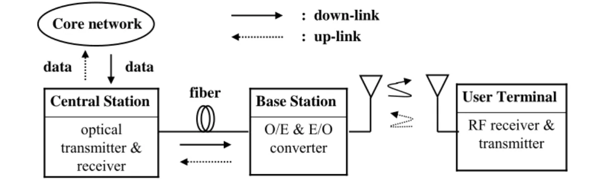
How the user receives the data from the core network at down-link or the user transmits the data to the core network at up-link in wireless communication system? At down-link, the central station (CS) is received the data form the core network first. Then the CS generates the electrical mm-wave signal concluded data and delivers the
data to user terminal (UT). The direct delivery from CS to UT of the electrical mm-wave wireless signal over a long distance is not feasible because the power loss of electrical mm-wave wireless signal is too much, and this situation is happened at up-link too. In order to solve this problem, the base stations (BS) are set up between CS and UT to re-amplifier the electrical mm-wave wireless signal until the RF signals can be received through antennas or mobile interface at UT, as shown in Fig.1-1.
optical transmitter & receiver Central Station RF receiver & transmitter User Terminal Core network data data : down-link : up-link
Fig. 1-1 Basic structure of microwave/millimeter-wave wireless system
Re-amplifier Base Station Re-amplifier Base Station However, the cost of setting up BSs over a long transmission distance is expensive. Hence, about in 1990, there are several optical mm-wave generation and transport techniques were built [1]. The BSs are only set up near the UTs, and the signal transmission between CS and BS is used fiber as communication medium, as shown in Fig.1-2.
optical transmitter &
receiver
Central Station
O/E & E/O converter Base Station RF receiver & transmitter User Terminal fiber Core network data data : down-link : up-link
1.2 Motivation
Recently, the simultaneous modulation and transmission of a RF signal and a BB signal has been demonstrated [2-5]. However, [2-3] the generated hybrid BB and RF signals suffer from performance fading problem caused by fiber dispersion. Therefore, a dispersion-shifting fiber (DSF) is employed to transmit the hybrid signals. This negative effect limits implementation to green field application only, rather than the most common application with already installed standard single mode fiber (SSMF). Furthermore, [4-5] only one signal is modulated on the optical subcarrier such that the BB and RF signals are identical after square-law PD detection. Hence, a simple and cost-effective modulation and transmission of the independent BB and RF signals without periodical performance fading due to fiber dispersion are required.
Chapter 2
The new architecture of hybrid optical access network
2.1 Preface
There are three parts in optical communication systems : optical transmitter, communication channel and optical receiver. Optical transmitter converts an electrical input signal into the corresponding optical signal and then launch it into the optical fiber serving as a communication channel. The role of an optical receiver is to convert the optical signal back into electrical form and recover the data transmitted through the lightwave system. In this chapter, we will do an introduction about the external integrated modulator, constructing a model of RoF system and constructing a model of new hybrid optical access network.
2.2 Mach-Zehnder Modulator (MZM)
Direct modulation and external modulation are two modulations of generated optical signal. When the bit rate of direct modulation signal is above 10 Gb/s, the frequency chirp imposed on signal becomes large enough. Hence, it is difficult to apply direct modulation to generate microwave/mm-wave. However, the bandwidth of signal generated by external modulator can exceed 10 Gb/s. Presently, most RoF systems are using external modulation with Mach-Zehnder modulator (MZM) or Electro-Absorption Modulator (EAM). The most commonly used MZM are based on LiNbO3 (lithium niobate) technology. According to the applied electric field, there are
two types of LiNbO3 device : x-cut and z-cut. According to number of electrode,
there are two types of LiNbO3 device: dual-drive Mach-Zehnder modulator
2.3 External integrated modulator
The SD-MZM has two arms and an electrode. The optical phase in each arm can be controlled by changing the voltage applied on the electrode. When the lightwaves are in phase, the modulator is in “on” state. On the other hand, when the lightwaves are in opposite phase, the modulator is in “off ” state, and the lightwave can not propagate by waveguide for output. When the amplitude imbalance between the arms duo to fabrication errors in MZM structure existed, there is some residual lightwave even in the “off ” state. The residual lightwave will limit the extinction ratio. However, we can compensate the amplitude imbalance by using the intensity trimmers, as shown in Figure 2-1. The intensity trimmers can be constructed by MZ structures. [7]
Intensity trimmer
Intensity trimmer
Fig 2-1 The Mach-Zehnder modulator has two intensity trimmers on the arms
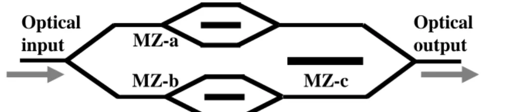
Figure 2-2 shows the structure of an external integrated modulator. The external integrated modulator using x-cut LiNbO3 [8-9], consists of three SD-MZM.
Two sub-MZMs (MZ-a and MZ-b) are embedded in each arm of the main modulator (MZ-c). Optical output MZ-a Optical input MZ-b MZ-c
2.4 The architecture of RoF system
2.4.1 Optical transmitter
Optical transmitter concludes optical source, modulator, etc.. Presently, most RoF systems are using laser as light source. The advantages of laser are compact size, high efficiency, good reliability small emissive area compatible with fiber core dimensions, and possibility of direct modulation at relatively high frequency [14]. The modulator is used for converting electrical signal into optical form. Because the external integrated modulator was composed of MZMs, we select MZM as modulator to build the architecture of optical transmitter.
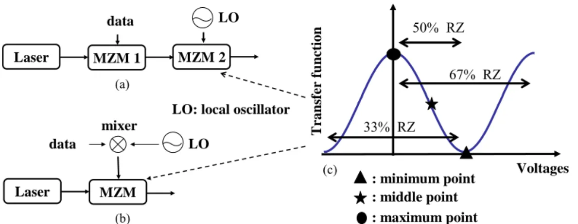
There are two schemes of optical transmitter generated optical signal. One scheme is used two MZM. First MZM generates optical carrier which carried the data. The output optical signal is BB signal. The other MZM generates optical subcarrier which carried the BB signal and then output the RF signal, as shown in Fig. 2-3 (a). The other scheme is used a mixer to get up-converted electrical signal and then send it into a MZM to generate the optical signal, as shown in Fig. 2-3 (b). Fig. 2-3 (c) shows the duty cycle of subcarrier biased at different points in the transfer function.
Voltages Transf er f u nction 50% RZ 67% RZ 33% RZ Laser MZM 1 data MZM 2
Fig 2-3 (a) and (b) are two schemes of transmitter and (c) is duty cycle of subcarrier LO Laser MZM data mixer LO (a) (b) (c) : minimum point : middle point : maximum point LO: local oscillator
2.4.2 Optical microwave/mm-wave signal generations based on LiNbO3 MZM
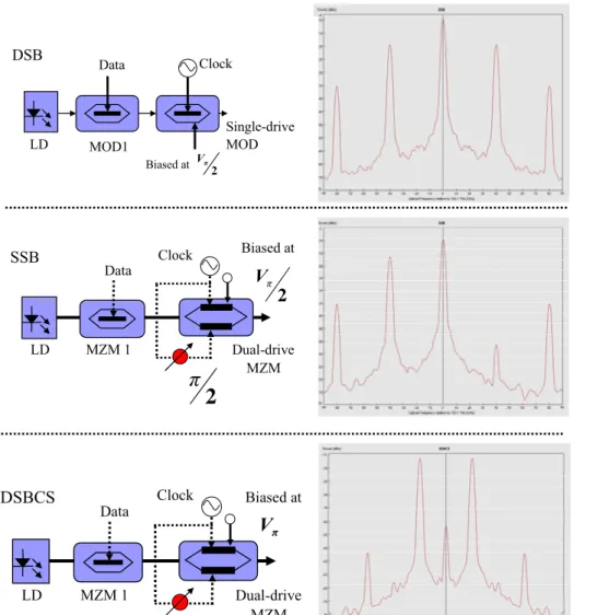
The microwave and mm-wave generations are key techniques in RoF systems. The optical mm-waves using external MZM based on double-sideband (DSB), single-sideband (SSB), and double-sideband with optical carrier suppression (DSBCS) modulation schemes have been demonstrated [10-12], as shown in Fig. 2-4. Generated optical signal by setting the bias voltage of MZM at quadrature point, the DSB modulation experiences performance fading problems due to fiber dispersion, resulting in degradation of the receiver sensitivity. What is RF fading? When an optical signal is modulated by an electrical RF signal, fiber chromatic dispersion causes the detected RF signal power to have a periodic fading characteristic [12].
The SSB signal is generated when a phase difference of π/2 is applied between the two RF electrodes of the DD-MZM biased at quadrature point. Although the SSB modulation can reduce the impairment of fiber dispersion, it suffers worse receiver sensitivity than DSB modulation [11]. In [5], DSBCS modulation is demonstrated at the mm-wave range with the best receiver sensitivity, lowest spectral occupancy, lowest bandwidth requirement for RF signal, electrical amplifier, and optical modulator, and smallest power penalty of receiver sensitivity after long transmitted distance [5][13].
2.4.3 Communication channel
Communication channel concludes fiber, optical amplifier, etc.. Presently, most RoF systems are using single-mode fiber (SMF) or dispersion compensated fiber (DCF) as the transmission medium. When the optical signal transmits in optical fiber, dispersion will be happened. DCF is use to compensate dispersion. The transmission distance of any fiber-optic communication system is eventually limited by fiber losses. For long-haul systems, the loss limitation has traditionally been overcome using
regenerator witch the optical signal is first converted into an electric current and then regenerated using a transmitter. Such regenerators become quite complex and expensive for WDM lightwave systems. An alternative approach to loss management makes use of optical amplifiers, which amplify the optical signal directly without requiring its conversion to the electric domain [14]. Presently, most RoF systems are using erbium-doped fiber amplifier (EDFA). An optical band-pass filter (OBPF) is necessary to filter out the ASE noise. The model of communication channel is shown in Fig. 2-5.
Fig 2-4 Optical microwave/mm-wave modulation scheme by using MZM
Data Clock Single-drive MOD DSB MOD1 LD Biased at 2 π V Clock Biased at π V Data Dual-drive MZM DSBCS MZM 1 LD
π
Biased at 2 π V Clock Data Dual-drive MZM SSB MZM 1 LD2
π
OBPF
EDFA fiber
Modulated optical signal
Fig 2-5 The model of communication channel in a RoF system
2.4.4 Demodulation of optical microwave/millimeter-wave signal
Optical receiver concludes photo-detector (PD), demodulator, etc.. PD usually consists of the photo diode and the trans-impedance amplifier (TIA). In the microwave or the mm-wave system, the PIN diode is usually used because it has lower transit time. The function of TIA is to convert photo-current to output voltage.
The BB and RF signals are identical after square-law PD detection. We can get RF signal by using a mixer to drop down RF signal to baseband then filtered by low-pass filter (LPF).
After getting down-converted signal, it will be sent into a signal tester to test the quality, just like bit-error-rate (BER) tester or oscilloscope, as shown in Fig. 2-6.
PD LPF mixer LO BERT after transmitting optical signal
Fig 2-6 The model of receiver in a RoF system
Combining the transmitter with communication channel and receiver, that is the
model of RoF system, as shown in Fig. 2-7. We select the scheme of Fig. 2-3 (b) to become the transmitter in the model of RoF system.
Laser MZM data mixer LO OBPF EDFA fiber PD LPF mixer LO BERT
Fig 2-7 The model of RoF system
Fig. 2-8 shows the model of BB signal generation. Not the same as the model of RoF system, the mixer which set to raise or drop down frequency is not necessary in the model of BB signal generation. But the modulation speed of the MZM needs to cover the data rate of the BB signal.
Laser MZM data OBPF EDFA fiber PD LPF BERT
Fig 2-8 The model of BB signal generation
2.5 The new model of hybrid optical access network
In section 2.3.2, there is an introduction of three modulation schemes of optical RF signal. In this experiment, SSB scheme can not be applied to generate optical RF signal because it needs a DD-MZM.
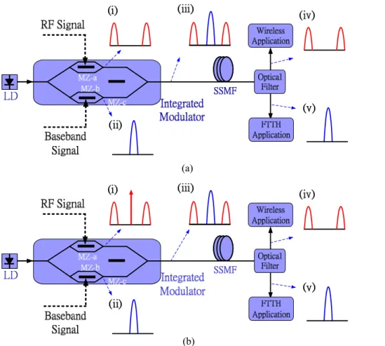
Fig. 2-9 (a) and (b) schematically depicts the hybrid optical access network system. A BB signal is modulated on the optical carrier and a RF signal on the optical double sideband. The RF signal using DSBCS modulation scheme is generated at
MZ-a biased at the minimum transmission point and the RF signal using DSB modulation scheme is generated at MZ-a biased at the middle transmission point, as shown in inset (i) of Fig. 2-9 (a) and (b). Moreover, the BB signal can be modulated at the optical carrier, as shown in the inset (ii) of Fig. 2-9 (a) and (b). The optical BB signal is generated at MZ-b. The optical RF signal and BB signal are combined at MZ-c which is hybrid signal, biased at the maximum transmission point, as shown in inset (iii) of Fig. 2-9 (a) and (b). At a remote node, a fiber grating is utilized to separate these two signals, as shown in inset (iv) and (v) of Fig. 2-9 (a) and (b), and each signal is transmitted to the corresponding application.
(a)
(b)
Fig. 2-9The model of hybrid optical access network. (a) use DSBCS scheme to generate RF signal
Chapter 3
Generation of RF Signal Using Only One
Single-Electrode Mach-Zehnder Modulator
3.1 Conventional experiment
In the conventional DSBCS modulation scheme, the BB signal is generated using a SD-MZM biased at quadrature and then up-converted using a DD-MZM biased at the minimum transmission point. The power penalty of RF signal after 20km transmission is negligible. After 40km, the power penalty is 2 dB [5]. In this chapter, we will build a new experimental setup from the RoF architecture.
3.2 Experimental components parameter
Name Model Parameter Note
Mixer 1 (5GHz) REMEC, MM47PL RF: 2~8GHz LO: 2~8GHz IF: DC~1.5GHz
Double balanced mixer, Up-converted signal Mixer 2 (10GHz) REMEC, MM96PL RF: 6~18GHz LO: 6~18GHz IF: DC~3GHz
Double balanced mixer, Down-converted signal Driver
amplifier
Picosecond 5865 Max output Vp-p : 7V
RF signal is limited by driver amplifier Dual-drive MZM Sumitomo Osaka Cement co.,ltd Vπ :5V MI-RF: Vp-p / (2 Vπ) Single-drive MZM JDS Uniphase OC-192 Vπ :5V MI-RF: Vp-p / (2 Vπ) EDFA Nice, EDFA20A Gain:approximate 20dB Amplify signal Optical BPF JDS Uniphase,
TB4500B
Bandwidth:50GHz Filter out ASE noise
3.3 Experimental setup and results using a DD-MZM based on
DSBCS modulation
3.3.1 Experimental setup
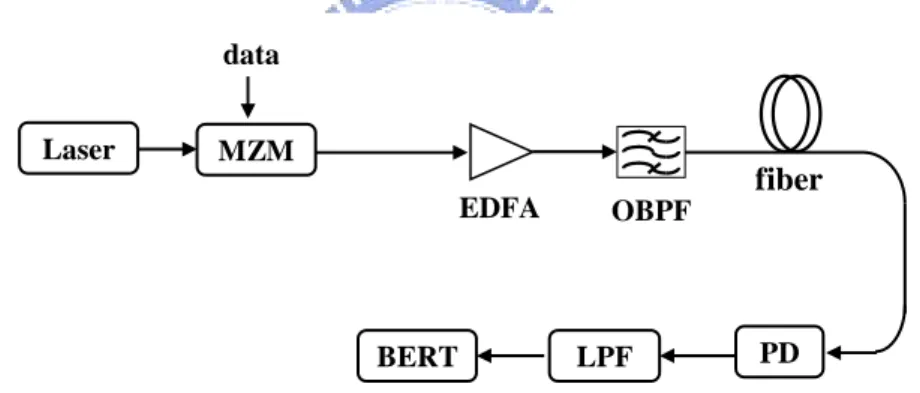
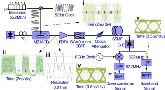
Figure 3-1 shows the experimental setup used for optical microwave generation and transmission based on DSBCS modulation scheme. Due to lack of high frequency components in our laboratory, we use a 622 Mb/s optical BB signal carrying a 10 GHz optical microwave. The continuous-wave (CW) laser is generated by a distributed feedback laser, and the emission wavelength is 1540 nm. The BB signal is 622 Mb/s pseudo random bit sequence (PRBS) signal with a word length of 231-1 and up-converted with the 5 GHz clock as shown in inset (i) of Figure 3-1. The up-converted signal is amplified to maximum peak-to-peak voltage (Vp-p) of 7 volt,
limited by the driver amplifier. The CW laser is modulated via external SD-MZM or DD-MZM with half-wave voltage (Vπ) of 5 volt. In order to realize DSBCS
modulation, the MZM is biased at the minimum transmission point. The repetition frequency of the generated optical microwave is 10 GHz. The optical microwave and spectrum are shown in insets (ii) and (iii) of Figure 3-1. The generated optical signal is amplified by EDFA and then filtered by a optical tunable filter with a bandwidth of 0.4 nm. The power of RF signal which entered fiber is set to 0 dBm to reduce the effect of both fiber nonlinearity and dispersion changing the duty cycle of optical microwaves.
After transmitted over standard single mode fiber (SSMF), the transmitted optical microwave signal is converted into an electrical microwave signal by a PIN PD with a 3 dB bandwidth of 38 GHz, and the converted electrical signal is amplified by an electrical amplifier. In the BB path, a LPF with a 3 dB bandwidth of 622 MHz is inserted to reject the undesired RF components. In the other path, the microwave signal is down-converted by a mixer with a 10 GHz clock, and then passes through a
LPF with a 3 dB bandwidth of 622 MHz. The eye diagrams of the down-converted and BB signals are shown in insets (iv) and (v) of Fig.3-1. Both the down-converted and BB signals are tested by a bit-error-ratio (BER) tester. We set the fiber length to be 25, 50 and 75 km.
Fig. 3-1 Experimental setup for optical microwave generation based on DSBCS modulation scheme
using one MZM.
3.3.2 Optimal condition for RF signal
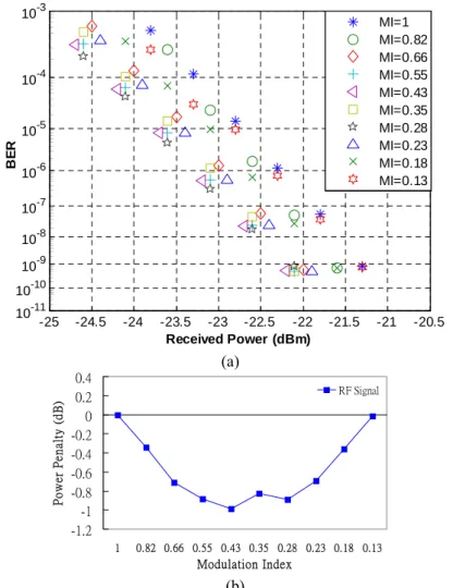
Figure 3-2 and Figure 3-3 show the variation of the receiver sensitivities of the down-converted and BB signals with different modulation index (MI, MI=Vp-p/2Vπ).
For the down-converted signal, the receiver sensitivity increases first and then decreases when MI ranges from 1 to 0.13, and the best sensitivity is at MI equal to 0.43. For the BB signal, no receiver sensitivity penalty is observed when MI decrease from 1 to 0.43.
The MZM nonlinearity and optical carrier suppression ratio (OCSR) are closely related to MI. As RF MI for MZM decreases, the MZM nonlinearity and OCSR decrease. The reduction of the MZM nonlinearity makes the duty cycle of optical microwaves closer to 0.5 as shown in Figure 3-4. At the same optical power, smaller
duty cycle of optical microwaves has higher peak power, resulting in better receiver sensitivity of the down-converted signal. However, low OCSR means that the RF component of optical power is relative low and the dc component of optical power at the center wavelength is relative high as shown in Figure 3-5. This incurs worse receiver sensitivity of the down-converted signal. Therefore, there is a trade-off for the receiver sensitivity of the down-converted signal between the MZM nonlinearity and OCSR when we decrease MI. When the optimal MI is 0.43, the receiver sensitivities of the BB and down-converted signals at BER of 10-9 are -22.6 dBm and -22.3 dBm. The receiver sensitivity of the down-converted signal has 1 dB improvement when MI changes from 1 to 0.43.
-1.2 -1 -0.8 -0.6 -0.4 -0.2 0 0.2 0.4 1 0.82 0.66 0.55 0.43 0.35 0.28 0.23 0.18 0.13 Modulation Index Po w er Pe n alty ( d B ) RF Signal -25 -24.5 -24 -23.5 -23 -22.5 -22 -21.5 -21 -20.5 10-11 10-10 10-9 10-8 10-7 10-6 10-5 10-4 10-3 Received Power (dBm) BE R MI=1 MI=0.82 MI=0.66 MI=0.55 MI=0.43 MI=0.35 MI=0.28 MI=0.23 MI=0.18 MI=0.13 (a) (b)
Fig. 3-2 BER curves (a) and power penalty (b) of down-converted signal for different MI.
-0.2 0 0.2 0.4 0.6 0.8 1 1.2 1.4 1.6 1 0.82 0.66 0.55 0.43 0.35 0.28 0.23 0.18 0.13 Modulation Index Po w er Pe n alty ( d B ) BB Signal -26 -25 -24 -23 -22 -21 10-11 10-10 10-9 10-8 10-7 10-6 10-5 10-4 10-3 Received Power (dBm) BE R MI=1 MI=0.82 MI=0.66 MI=0.55 MI=0.43 MI=0.35 MI=0.28 MI=0.23 MI=0.18 MI=0.13 (a) (b)
Fig. 3-3 BER curves (a) and power penalty (b) of BB signal for different MI.
MI=1 MI=0.66 MI=0.43 MI=0.28 MI=0.18
Fig. 3-4 Duty cycles of optical microwaves based on DSBCS modulation. The optical microwave
power is 0dBm. The optical power scale is 0.8 mW/div and the time scale is 20 ps/div.
MI=1 MI=0.66 MI=0.43 MI=0.28 MI=0.18
3.3.3 Transmission results
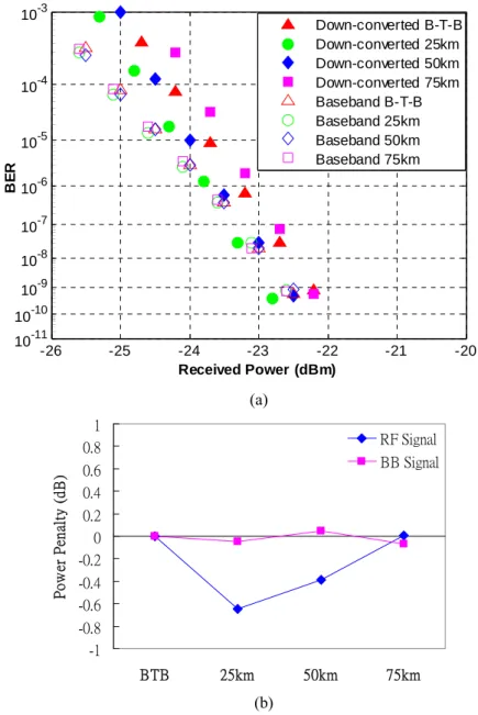
After optical microwaves with optical power of 0 dBm, using the optimal MI equal to 0.43, are transmitted over 25 km, 50 km, and 75 km SSMF, no power penalty for the receiver sensitivities of the BB and down-converted signals at BER of 10-9 is observed as shown in Fig.3-6.
-26 -25 -24 -23 -22 -21 -20 10-11 10-10 10-9 10-8 10-7 10-6 10-5 10-4 10-3 Received Power (dBm) BE R Down-converted B-T-B Down-converted 25km Down-converted 50km Down-converted 75km Baseband B-T-B Baseband 25km Baseband 50km Baseband 75km -1 -0.8 -0.6 -0.4 -0.2 0 0.2 0.4 0.6 0.8 1 BTB 25km 50km 75km P o w er Pe na lt y ( dB ) RF Signal BB Signal
Fig. 3-6 BER curves using one DD-MZM with MI of 0.43 after transmitted over 25 km,
50 km and 75 km SSMF.
(a)
3.4 Experimental setup and results using a SD-MZM based on
DSBCS modulation
Based on the result of DSBCS modulation using one DD-MZM, we can generate DSBCS microwaves using only one SD-MZM with MI equal to 0.43 in the same experimental setup. The Vπ of the SD-MZM at 5GHz is 5 volt, and the Vp-p for
the MI of 0.43 is 4.3 volt. Fig.3-7 shows the receiver sensitivities of the BB and down-converted signals with optical power of 0 dBm after they are transmitted over 25 km, 50 km and 75 km SSMF. The power receiving penalties for both the BB and down-converted signals at BER of 10-9 are less than 0.3 dB.
-26 -25 -24 -23 -22 -21 -20 -19 10-11 10-10 10-9 10-8 10-7 10-6 10-5 10-4 10-3 Received Power (dBm) BE R Down-converted B-T-B Down-converted 25km Down-converted 50km Down-converted 75km Baseband B-T-B Baseband 25km Baseband 50km Baseband 75km -1 -0.8 -0.6 -0.4 -0.2 0 0.2 0.4 0.6 0.8 1 BTB 25km 50km 75km Pow er Pena lt y ( dB ) RF Signal BB Signal (a) (b)
Fig. 3-7 BER curves using one SD-MZM with MI of 0.43 after transmitted over 25 km,
3.5 Discussions
In this chapter, we experimentally demonstrate a generation of RF signals based on DCBCS modulation scheme using only one SD-MZM. The optimal MI level for driving DD-MZM is 0.43 with 1 dB sensitivity improvement for down-converted signals, and the power penalty after transmitted over 75 km SSMF is less than 0.4dB. Then this result will be applied to generate RF signal by the sub-MZ of the external integrated modulator.
Chapter 4
Hybrid Optical Access Network Integrating
Fiber-to-the-home and Radio-over-fiber Systems
4.1 Preface
In chapter 3, we prove that the generation of RF signal using only one SD-MZM base on DSBCS scheme is workable. Therefore, the result can be tried to apply to the external integrated modulator. If the BB signal could be modulated by the other sub-MZ of the external integrated modulator, that is, simultaneously generate and transmission of a wired-line BB signal and a wireless RF signal on a single wavelength using one external integrated modulator, then FTTH and RoF systems share a single distributed infrastructure. The integrated system is called the hybrid optical access network.
1554.85-20 1554.9 1554.95 1555 1555.05 -10 0 R e fl ec ti on ( dB ) Wavelength (nm) 1554.85 1554.9 1554.95 1555 1555.05-30 -20 -10 0 T rans m is si o n ( dB ) Reflection Transmission
Fig. 4-1 The reflection spectrum and transmission spectrum of grating
4.2 Experimental components parameter
Table 4-1 shows the experimental components. Figure 4-1 shows the reflection and transmission spectrum of grating.
Name Type number Parameter Note
Mixer 1 (10GHz) REMEC, MM96PL RF: 6~18GHz LO: 6~18GHz IF: DC~3GHz
Double balanced mixer, in order to generate the
up-converted signal Mixer 2 (20GHz) SPECTRUM, MC134PN-3 RF: 17~24GHz LO: 15~26GHz IF: DC~4GHz
Double balanced mixer, in order to generate the down-converted signal Driver
amplifier
Picosecond 5865 Max output Vp-p : 7V RF signal is limited by RF amplifier External integrated modulator SUMITOMO OSAKA CEMENT CO., T․FSK․1.5-10-S-FK Modulation speed : 10Gb/s Optical bandwidth: >10GHz(RFA, RFB, RFC) MI-RF: Vp-p / (2 MZ-a Vπ) MI-BB: Vp-p / (MZ-b Vπ) Vπ of MZ-a, b, c : 5.8V, 5.6V, and 6.9V Optical BPF JDS Uniphase, TB4500B
Bandwidth: 0.4nm Filter out ASE noise EDFA Nice, EDFA20A Gain:approximate
20dB
Amplify signal
Photo detector u2T, XPRV2022 3dB bandwidth: 38GHz PIN photo diode/TIA module
Grating INDIGO, photonics IP-CS0014-1554.94
Wavelength: 1554.94nm 3dB bandwidth: 4GHz
Separate RF and baseband signals
Table 4-1 Experimental components.
4.3 Experimental setup and results of hybrid signal which RF signal
using DSBCS modulation
4.3.1 Experimental setup
Fig.4-2 shows the experimental setup for hybrid signal generation and transmission using one external integrated modulator based on DSBCS modulation.
The CW laser is generated by a tunable laser, and the lasing wavelength is 1554.94nm. The RF signal is a 622Mb/s PRBS signal with a word length of 231-1 and up-converted with the 10 GHz clock as shown in inset (i) of Fig.4-2. The up-converted RF signal is amplified to maximum Vp-p of 7V, limited by the RF
amplifier. The optical RF signal is generated via MZ-a with half-wave voltage (Vπ) of
5.8V. The MZ-a is biased at the minimum transmission point to realize DSBCS modulation. The repetition frequency of the generated optical microwave is 20GHz, as shown in inset (ii) of Fig.4-2. The BB signal is a 1.25Gb/s PRBS signal with a word length of 231-1; it is sent into MZ-b with Vπ of 5.6V. The eye diagram of the
generated optical BB signal is shown in inset (iii) of Fig. 4-2. The optical RF and BB signals are combined in MZ-c with Vπ of 6.9V. The hybrid optical signals are
amplified by EDFA to compensate for the loss of the external modulator, yielding a power of 0dBm before transmission over 50km SSMF.
Following transmission over 50km SSMF, the hybrid signals are preamplified by EDFA and then filtered by a tunable optical filter with a bandwidth of 0.4nm. At the remote node, the fiber grating with a 3dB bandwidth of 4GHz is used to separate these two signals, as shown in inset (iv) and (v) of Fig. 4-2, and each signal is sent to the corresponding application. Both optical signals are individually detected by a PIN PD. For FTTH applications, the electrical BB signal is filtered by an electrical filter with a 3dB bandwidth of 1.25GHz. For wireless applications, the electrical RF signal is down-converted by a mixer with a 20GHz clock before passing through a LPF with a 3dB bandwidth of 622MHz. The eye diagrams of BB and RF signals are shown in inset (vi) and (vii) of Fig. 4-2. Both RF and BB signals are tested by a BER tester and the receiver sensitivities are measured before EDFA pre-amplification. The fiber length is set to 25 and 50km.
Fig.4-2 Experimental setup for RF and BB signal generation and transmission by using
one external integrated modulator based on DSBCS modulation.
4.3.2 Optimal condition for RF signal
The RF signal performance is closely related to MZM nonlinearity. To optimize the RF signal performance, the modulation index (MI-RF, MI-RF= Vp-p/2Vπ) for
driving MZ-a decreases form 0.6 to 0.1 and no BB signals are sent to MZ-b biased at the minimum transmission point. Figure 4-3 shows the variation of the receiver sensitivity of the RF signal with different MI-RF. The RF receiver sensitivity initially improves and then declines as the MI-RF decreases from 0.6 to 0.1 When MI-RF is 0.48, the RF signals exhibit the best sensitivity and the sensitivity is -39.22dBm.
The optimal MI-RF originates from the trade-off between the MZM nonlinearity and the OCSR for the RF receiver sensitivity when MI-RF is decreased. As MI-RF decreases, the MZM nonlinearity decreases and the subcarrier varies, as shown in figure 4-4. Hence, the RF sensitivity will improve with MI-RF. However,
the OCSR decreases as MI-RF decreases, as shown in figure 4-5.
Low OCSR means that the optical power of the subcarrier is relative low and that of the optical carrier is relative high. This incurs worse receiver sensitivity of the RF signal. Therefore, there is a trade-off for the receiver sensitivity of the RF signal between the MZM nonlinearity and the OCSR when we decrease MI.
-44 -42 -40 -38 -36 -34 -32 -30 10-11 10-10 10-9 10-8 10-7 10-6 10-5 10-4 10-3 Received Power (dBm) BE R MI-RF=0.6 MI-RF=0.53 MI-RF=0.48 MI-RF=0.4 MI-RF=0.33 MI-RF=0.26 MI-RF=0.17 MI-RF=0.1 -28 -2 0 2 4 6 8 10 0.6 0.53 0.48 0.4 0.33 0.26 0.17 0.1 Modulation Index Pow er P ena lt y (d B ) RF Signal (a) (b)
MI-RF=0.6 MI-RF=0.53 MI-RF=0.48 MI-RF=0.4
MI-RF=0.33 MI-RF=0.26 MI-RF=0.17 MI-RF=0.1
Fig 4-4 Subcarrier variation of RF signals for MI-RF from 0.6 to 0.1. The optical microwave power
is 0dBm ( Power sale : 600uW/div, Time scale : 10ps/div )
MI-RF=0.6 MI-RF=0.53 MI-RF=0.48 MI-RF=0.4
MI-RF=0.33 MI-RF=0.26 MI-RF=0.17 MI-RF=0.1
Fig 4-5 Optical spectrum of RF signals for MI-RF from 0.6 to 0.1.
(Power scale : 5dB/div, resolution : 0.01nm)
consider the impact of MZM nonlinearity. The receiver sensitivity is greatly improved when MI changes from 0.6 to 0.53. As MI-RF changes from 0.53 to 0.1, only small improvement is observed, as shown in figure 4-6. Therefore, the MZM nonlinearity dominates the RF signal performance when MI-RF is between 0.6 and 0.53. As The MI-RF is below 0.5, the OCSR dominates the RF signal performance.
-23 -22 -21 -20 -19 -18 10-11 10-10 10-9 10-8 10-7 10-6 10-5 10-4 10-3 Received Power (dBm) BE R MI-RF=0.6 MI-RF=0.53 MI-RF=0.48 MI-RF=0.4 MI-RF=0.33 MI-RF=0.26 MI-RF=0.17 MI-RF=0.1 -1 -0.5 0 0.5 1 0.6 0.53 0.48 0.4 0.33 0.26 0.17 0.1 Modulation Index Po w er Pe n alty ( d B ) RF Signal (a) (b)
Fig. 4-6 BER curves of RF signal which the optical carrier is filtered by grating and
-45 -40 -35 -30 -25 -20 -15 10-11 10-10 10-9 10-8 10-7 10-6 10-5 10-4 10-3 Received Power (dBm) BE R RF(MI-BB=1) BB(MI-BB=1) RF(MI-BB=0.8) BB(MI-BB=0.8) RF(MI-BB=0.63) BB(MI-BB=0.63) RF(MI-BB=0.45) BB(MI-BB=0.45) RF(MI-BB=0.27) BB(MI-BB=0.27) RF(MI-BB=0.18) BB(MI-BB=0.18)
-6
-4
-2
0
2
4
6
8
10
1 0.8 0.63 0.45 0.27 0.18 MI-BBPo
w
er
Pe
n
alty
(
d
B
)
RF Signal BB Signal (a) (b)Fig. 4-7 BER curves (a) and power penalty (b) of both RF and BB signals for MI-BB
from 1 to 0.18. MI-RF is fixed at 0.48
4.3.3 Transmission condition for hybrid signal
Vp-p/Vπ), the optimal MI-RF for driving MZ-a is fixed at 0.48, and then the BB signal
is sent to MZ-b. The MI-BB for driving MZ-b decreases from 1 to 0.18 to yield the same sensitivities of the BB and RF signals. The bias point of MZ-b is adjusted to maximize the extinction ratio of the BB signal as MI-BB varies from 1 to 0.18. Unlike in other works [2-3], the RF and BB signals are generated at the different sub-MZMs. Various MI-BBs for driving MZ-b cannot influence the RF signal performance when MI-RF for driving MZ-a is maintained at 0.48. As MI-BB decreases, the optical power ratios of the RF and BB signals to the hybrid signals increase and decrease. Hence, the BB sensitivity increases and the RF sensitivity decreases as MI-BB ranges from 1 to 0.18, as shown in Fig.4-7. When the MI-BB is 0.27, the same sensitivities of the RF and BB signals can be achieved. Under optimal conditions for driving MZ-a and MZ-b, the receiver sensitivities of the RF and BB signals are -37.2dBm and -36.8dBm at BER of 10-9. When the MI-BB is 0.18, the sensitivity of RF is -39.04.
Fig. 4-8 shows the sensitivity measurement of RF signal separated by the grating when the MI-RF is fixed at 0.48 and MI-BB is decreased. It is obviously when the MI-BB is decreased, the sensitivity of RF signal is no variation. It prove that no interference issue exists between RF and BB signal.
The inset (i) ~ (vii) of Figure 4-2 and the inset (i) ~ (v) of Figure 4-9 are eye diagrams and optical spectrums of RF and BB signals when MI-RF and MI-BB were 0.48 and 0.27. At Figure 4-9, the inset (i) and (ii) are optical spectrums of RF and BB signals after modulated, the inset (iii) is optical spectrum of hybrid signal, the inset (iv) and (v) are optical spectrums of RF and BB signals separated from hybrid signal by grating. The inset (v) of Figure 4-9 shows that the grating performance of reflection part is not very good. In order to decrease the influence of grating on BB signal, a LPF was set after O/E converter, as shown in Figure 4-2. We set that MI-RF and MI-BB are 0.48 and 0.27 and transmit the hybrid signal.
-22.5 -22 -21.5 -21 -20.5 -20 -19.5 -19 10-11 10-10 10-9 10-8 10-7 10-6 10-5 10-4 10-3 Received Power (dBm) BE R RF(MI-BB=1) RF(MI-BB=0.8) RF(MI-BB=0.63) RF(MI-BB=0.45) RF(MI-BB=0.27) RF(MI-BB=0.18) (a) (b)
Fig. 4-8 Sensitivity measurement (a) and BER curves (b)of RF signal separated by grating as MI-BB decreased
Fig. 4-9 Optical spectrum of BB and RF signals as MI-RF is fixed at 0.48 and MI-BB is fixed at 0.27.
4.3.4 Transmission results of hybrid signal
The optical hybrid signals at an optical power of 0dBm are transmitted over 25km and 50km SSMF. Figure 4-10 plots the BER curves of the RF and BB signals. The power penalties of both signals at a BER of 10-9 are less than 0.4dB.
4.3.5 Discussion
Although the RF signal using DSBCS modulation overcomes the RF fading and has the best receiver sensitivity [5], there is a limitation for the RF signals in our proposed system. The RF signals are restricted to amplitude-shifted keying signals due to elimination of the optical carrier. Besides, there is the other limitation among the RF frequency, the RF signal bandwidth, and the BB signal bandwidth. Therefore, to avoid the interference between RF and BB signals after fiber grating, the total data rate of the hybrid signals should be less than the RF frequency.
-42 -41 -40 -39 -38 -37 -36 10-11 10-10 10-9 10-8 10-7 10-6 10-5 10-4 10-3 Received Power (dBm) BE R RF BTB RF 25km RF 50km BB BTB BB 25km BB 50km
for driving MZ-a and MZ-b are 0.48 and 0.27.
-1 -0.8 -0.6 -0.4 -0.2 0 0.2 0.4 0.6 0.8 1 BTB 25km 50km Po w er Pe na lt y (d B ) RF Signal BB Signal (a) (b)
Fig. 4-10 BER curves (a) and power penalty (b) of both RF and BB signals following
4.4
Experimental setup and results of hybrid signal which RF signal
using DSB modulation
4.4.1 Experimental setup
Figure 4-11 shows the experimental setup for hybrid signal generation and transmission using one external integrated modulator based on DSB modulation. The CW laser is generated by a tunable laser, and the lasing wavelength is 1554.94nm. The RF signal is a 622Mb/s PRBS signal with a word length of 231-1 and up-converted with the 10 GHz clock as shown in inset (i) of Fig.4-11. The up-converted RF signal is amplified to maximum Vp-p of 7V, limited by the RF
amplifier. The optical RF signal is generated via MZ-a with Vπ of 5.8V. The MZ-a is
biased at the middle transmission point to realize DSB modulation. The repetition frequency of the generated optical microwave is 10GHz, as shown in inset (ii) of Fig.4-11. The BB signal is a 1.25Gb/s PRBS signal with a word length of 231-1; it is sent into MZ-b with Vπ of 5.6V. The eye diagram of the generated optical BB signal is
shown in inset (iii) of Fig. 4-11. The optical RF and BB signals are combined in MZ-c with Vπ of 6.9V. The hybrid optical signals are amplified by an EDFA to compensate
for the loss of the external modulator, yielding a power of 0dBm before transmission over 50km SSMF. Following transmission over 50km SSMF, the hybrid signals are preamplified by EDFA and then filtered by a tunable optical filter with a bandwidth of 0.4nm. At the remote node, the fiber grating with a 3dB bandwidth of 4GHz is used to separate these two signals, as shown in inset (iv) and (v) of Fig. 4-11, and each signal is sent to the corresponding application. Both optical signals are individually detected by a PIN PD. For FTTH applications, the electrical BB signal is filtered by an electrical filter with a 3dB bandwidth of 1.25GHz. For wireless applications, the electrical RF signal is down-converted by a mixer with a 20GHz clock before passing
through a LPF with a 3dB bandwidth of 622MHz. The eye diagrams of BB and RF signals are shown in inset (vi) and (vii) of Fig. 4-11. Both RF and BB signals are tested by a BER tester and the receiver sensitivities are measured before EDFA pre-amplification. The fiber length is set to 25 and 50km.
Fig.4-11 Experimental setup for RF and BB signal generation and transmission by using one external integrated modulator based on DSB modulation.
4.4.2 Optimal condition for RF signal
To optimize the RF signal performance, the MI-RF (MI-RF= Vp-p / Vπ) for
driving MZ-a decreases form 1 to 0.16 for RF signal using DSB modulation and no BB signal is sent to MZ-b. Figure 4-12 shows the receiver sensitivity decreases with MI-RF although the MZM nonlinearity reduction can improve the RF signal performance. The reason is that the optical modulation index (OMI) decreases as MI-RF decreases. Figure 4-13 and 4-14 show the peak power and optical spectrum of optical RF signal declines as the MI-RF decreases from 1 to 0.16.When MI-RF is 1,
the RF signals exhibit the best sensitivity and the sensitivity is -32.024dBm. -40 -30 -20 -10 0 10 10-11 10-10 10-9 10-8 10-7 10-6 10-5 10-4 10-3 Received Power (dBm) BE R MI-RF=1 MI-RF=0.8 MI-RF=0.65 MI-RF=0.52 MI-RF=0.42 MI-RF=0.25 MI-RF=0.16 0 5 10 15 20 25 30 35 1 0.8 0.65 0.52 0.42 0.25 0.16 Modulation Index Po we r Pe n al ty ( d B ) RF Signal
Fig. 4-12 BER curves (a) and power penalty (b) of RF signal for MI-RF from 1 to 0.16. (b)
(a)
MI-RF=1 MI-RF=0.8 MI-RF=0.65 MI-RF=0.52
MI-RF=0.42 MI-RF=0.25 MI-RF=0.16
Fig. 4-13 Subcarrier variation of RF signals for MI-RF from 1 to 0.16. The microwave power
MI-RF=1 MI-RF=0.8 MI-RF=0.65 MI-RF=0.52
MI-RF=0.42 MI-RF=0.25 MI-RF=0.16
Fig. 4-14 Subcarrier variation of RF signals for MI-RF from 1 to 0.16.
( Power scale : 10dB/div, resolution : 0.01nm )
4.4.3 Transmission condition for hybrid signal
To optimize MI for BB signals (MI-BB, MI-BB= Vp-p/Vπ), the optimal MI-RF
for driving MZ-a is fixed at 1, and then the BB signal is sent to MZ-b. The MI-BB for driving MZ-b decreases from 1 to 0.27 to yield the same sensitivities of the BB and RF signals. The bias point of MZ-b is adjusted to maximize the extinction ratio of the BB signal as MI-BB varies from 1 to 0.27. As MI-BB decreases, the optical power ratios of the RF and BB signals to the hybrid signals increase and decrease. Hence, the BB sensitivity increases and the RF sensitivity decreases as MI-BB ranges from 1 to 0.27, as shown in Fig.4-15. Because the RF signal is generated based on DSB modulation, the carrier power occupies most of hybrid signal. Therefore, the increased and decreased scale of the optical power ratios of the RF and BB signals to the hybrid signals are not large .When the MI-BB is 0.27, there is an error floor appeared. From the eye diagram, it is quite obviously that the BB signal is very noisy. Because the BB signal is so weak that the noise can cause BB signal very noisy. So the same sensitivities of the BB and RF signals can not be found. We set that MI-RF and MI-BB are 1 and transmit the hybrid signal. The receiver sensitivities of the RF and BB signals are -26dBm and -39.8dBm at BER of 10-9 when MI-RF and MI-BB are 1.
-45 -40 -35 -30 -25 -20 -15 -10 10-11 10-10 10-9 10-8 10-7 10-6 10-5 10-4 10-3 Received Power (dBm) BE R RF(MI-BB=1) BB(MI-BB=1) RF(MI-BB=0.63) BB(MI-BB=0.63) RF(MI-BB=0.36) BB(MI-BB=0.36) RF(MI-BB=0.27) BB(MI-BB=0.27)
Fig. 4-15 BER curves of both RF and BB signals for MI-BB from 1 to 0.27. MI-RF is fixed at 1 .
Fig. 4-16 shows the sensitivity measurement of RF signal separated by the grating when the MI-RF is fixed at 1 and MI-BB is decreased. It is obviously when the MI-BB is decreased, the sensitivity of RF signal is no variation. It prove that no interference issue exists between RF and BB signal.
The inset (i) ~ (vii) of Figure 4-11 and the inset (i) ~ (v) of Figure 4-17 are eye diagrams and optical spectrums of RF and BB signals when MI-RF and MI-BB were 1 and 1. At Figure 4-17, the inset (i) and (ii) are optical spectrums of RF and BB signals after modulated, the inset (iii) is optical spectrum of hybrid signal, the inset (iv) and (v) are optical spectrums of RF and BB signals separated from hybrid signal by grating. The inset (v) of Figure 4-17 shows that the grating performance of reflection part is not very good. In order to decrease the influence of grating on BB signal, a LPF was set after O/E converter, as shown in Figure 4-11.
-18 -17.5 -17 -16.5 -16 -15.5 10-11 10-10 10-9 10-8 10-7 10-6 10-5 10-4 10-3 Received Power (dBm) BE R RF(MI-BB=1) RF(MI-BB=0.63) RF(MI-BB=0.36) RF(MI-BB=0.27) (a) (b) Optimal MI-RF=1
Fig. 4-16 Sensitivity measurement (a) and BER curves (b)of RF signal separated by grating as MI-BB decreased
1554.7 1554.75 1554.8 1554.85 1554.9 1554.95 1555 1555.05 -80 -70 -60 -50 -40 -30 -20 1554.651554.71554.751554.81554.851554.91554.95 1555 1555.05-50 -45 -40 -35 -30 -25 -20 -15 19dB 1554.651554.71554.751554.81554.851554.91554.95 1555 1555.05 -70 -60 -50 -40 -30 -20 -10 0 31dB 1554.651554.71554.751554.81554.851554.91554.95 1555 1555.05 -70 -60 -50 -40 -30 -20 -10 16dB 1554.7 1554.75 1554.8 1554.85 1554.9 1554.95 1555 1555.05 -75 -70 -65 -60 -55 -50 -45 -40 -35 -30 -25 -20 10dB
Fig. 4-17 Optical spectrum of BB and RF signals as MI-RF is fixed at 1 and MI-BB is fixed at 1.
4.4.4 Transmission results of hybrid signal
The optical hybrid signals at an optical power of 0dBm are transmitted over 25km and 50km SSMF. Figure 4-18 plots the BER curves of the RF and BB signals. The power penalties of both signals at a BER of 10-9 are less than 0.5dB.
4.4.5 Discussion
Although the RF signal using DSB modulation, there is no RF fading and interference issue in our proposed system. Comparing with DSBCS modulation, the sensitivity of RF and BB signals are worse.
-45 -40 -35 -30 -25 -20 -15 10-11 10-10 10-9 10-8 10-7 10-6 10-5 10-4 10-3 Received Power (dBm) BE R RF BTB RF 25km RF 50km BB BTB BB 25km BB 50km -1 -0.8 -0.6 -0.4 -0.2 0 0.2 0.4 0.6 0.8 1 BTB 25km 50km Po w er Pe n alty ( d B ) RF SignalBB Signal
Fig. 4-18 BER curves (a) and power penalty (b) of both RF and BB signals following
transmission over 25km and 50 km SSMF. The optimal MI-RF and MI-BB for driving MZ-a and MZ-b are 1 and 1.
(b) (a)
Chapter 5
Conclusion
This study experimentally demonstrates the simultaneous modulation and transmission of FTTH BB and RoF RF signals using one external integrated modulator. First, we experimentally demonstrate a generation of RF signals based on DCBCS modulation scheme using only one MZM. The optimal MI level for driving DD-MZM is 0.43 with 1 dB sensitivity improvement for down-converted signals, and there is no receiver sensitivity penalty after transmitted over 75 km SSMF. Based on the optimal MI of 0.43, we can generate DSBCS microwave using only one SD-MZM, and the receiver sensitivity penalty is less than 0.3 dB after transmitted over 75 km SSMF. Second, we apply this result in the external integrated modulator to generate RF signal and find the optimal MI level for driving MZ-a is 0.48. Next, the optimal MI-RF for driving MZ-a is fixed at 0.48, and then the BB signal is sent to MZ-b to find the same sensitivities of the BB and RF signals. Final, the optical hybrid signals at an optical power of 0dBm are transmitted over 25km and 50km SSMF, and the power penalties of both signals at a BER of 10-9 are less than 0.4dB. The results reveal that the proposed system has great potential for use in future multi-service access networks.
We try to demonstrate a generation of RF signals based on DCB modulation scheme and repeat the above-mentioned experiment. However, the performance is worse. The generated hybrid signals do not suffer from periodic performance fading problem caused by fiber dispersion and there is no interference between BB and RF signals on both modulation schemes.
REFERNCES
[1] Ken-Ichi Kitayama,“Architectural Considerations of Fiber-Radio Millimeter-Wave Wireless Access Systems”, Fiber and Integrated Optics, 19:167-186, 2000. [2] T. Kamisaka, T. Kuri, K. Kitayama, “Simultaneous modulation and fiber-optic
transmission of 10Gb/s baseband and 60GHz band radio signals on a single wavelength,” IEEE Trans. Microwave theory and Technol., vol. 49, pp. 2013-2017, 2001.
[3] K. Ikeda, T. Kuri, and K. Kitayama, “Simultaneous three band modulation and fiber-optic transmission of 2.5Gb/s baseband, microwave-, and 60GHz band signals on a single wavelength,” IEEE J. Lightwave Technol., vol. 21, pp. 3194-3202, 2003.
[4] A. Martinez, V. Polo, and J. Marti, “Simultaneous baseband and RF optical modulation scheme for feeding wireless and wireline heterogeneous access network,” IEEE Trans. Microwave theory and Technol., vol. 49, pp. 2018-2024, 2001.
[5] J. Yu, Z. Jia, L. Yi, G. K. Chang, and T. Wang, “Optical millimeter-wave generation or up-conversion using external modulator,” IEEE Photon. Technol. Lett., vol. 18, pp. 265-267, 2006.
[6] Ed L. Wooten, Karl M. Kissa, Alfredo Yi-Yan, Edmond J. Murphy, Donald A. Lafaw, Peter F. Hallemeier, David Maack, Daniel V. Attanasio, Daniel J. Fritz, Gregory J. McBrien, and Donald E. Bossi, “A Review of Lithium Niobate Modulators for Fiber-Optic Communications Systems”, IEEE Journal of selected topic in Quantum Electronics, Vol. 6, No.1, January/February 2000.
[7] Tetsuya Kawanishi, Takahide Sakamoto, Masahiro Tsuchiya and Masayuki Izutsu, “High Carrier Suppression Double Sideband Modulation Using an Integrated Modulator”, Microwave Photonics, MWP 2005, page 29-32, Oct. 2005.
[8] T. Kawanishi, K. Higuma, T. Fujita, S. Mori, S. Oikawa, J. Ichikawa , T. Sakamoto and M. Izutsu , “40Gbit/s Versatile LiNbO3 Lightwave Modulator ,”
European Conference on Optical Communication (ECOC 2005), Paper No.: Th2.2.5, 2005.
[9] T. Sakamoto, T. Kawanishi, and M. Izutsu, “Continuous-Phase Frequency-Shift Keying With External Modulation,” IEEE Journal OF Selected Topics in Quantum Electronics, Vol. 12, no. 4, pp. 589-595, July/August 2006.
[10] A. Martinez, V. Polo, and J. Marti, “Simultaneous baseband and RF optical modulation scheme for feeding wireless and wireline heterogeneous access network,” IEEE Trans. Microwave theory and Technol., vol. 49, pp. 2018-2024, 2001.
[11] M. Attygalle, C. Lin, G. J. Pendock, A. Nirmalathas, and G. Edvell, “Transmission improvement in fiber wireless links using fiber Bragg grating,” IEEE Photon. Technol. Lett., vol. 17, pp. 190-192, 2005.
[12] Andrew Liu, Graeme J. Pendock, and Rodney S. Tucker, “Improved chromatic dispersion monitoring using single RF monitoring tone”, OSA Optics Express, Vol. 14, No. 11, 29 May 2006.
[13] C. Lim, C. Lin, M. Attygalle, A. Nirmalathas, D. Novak, and R. Waterhouse, “Analysis of Optical Carrier-to-Sideband Ratio for Improving Transmission Performance in Fiber-Radio Links,” IEEE J. Lightwave Technol., vol. 54, no. 5, pp. 2181-2187, 2006.
[14] Govind P. Agrawal, “ Fiber-Optic Communication System”, third edition, a John Wiley& Sons, inc., publication.