國
立
交
通
大
學
電子工程學系 電子研究所
碩 士 論 文
在多核心系統上之高效能雙層計數布隆過濾器
A High Performance Double Layer Counting Bloom
Filter for Multicore System
研 究 生:陳冠廷
指導教授:賴伯承 教授
在多核心系統上之高效能雙層計數布隆過濾器
A High Performance Double Layer Counting Bloom
Filter for Multicore System
研究生:陳冠廷 Student:Kuan-Ting Chen
指導教授:賴伯承 Advisor:Bo-Cheng Lai
國 立 交 通 大 學
電子工程學系 電子研究所
碩 士 論 文
A ThesisSubmitted to Department of Electronics Engineering and Institute of Electronics
College of Electrical and Computer Engineering National Chiao Tung University
in partial Fulfillment of the Requirements for the Degree of
Master in
Electronics Engineering
March 2013
Hsinchu, Taiwan, Republic of China
在多核心系統上之高效能雙層計數布隆過濾器
研究生:陳冠廷 指導教授:賴伯承教授
國立交通大學
電子工程學系 電子研究所
摘 要
在對稱式多核心系統中,基於廣播的窺探式協議被很廣泛地用於維持快取記憶體一 致性。然而窺探式協議盲目地傳播整個系統的數據共享訊息,並且通常導致十分大量而 不必要的資料傳輸及快取記憶體中的資料搜尋。本文提出了一種新的硬體架構:雙層計 數布隆過濾器,並且使用該架構過濾在對稱式多核心系統中不必要的資料管理。透過階 層式雜湊函數的設計,雙層計數布隆過濾器可以管理較大的檢索空間,並且有效地增加 成功過濾的比例。相較於傳統的布隆過濾器,雙層計數布隆過濾器可以過濾掉 81.99% 更多的不必要的快取記憶體資料搜尋,並使用 18.75% 更少的記憶體。當應用於階層式 共享匯流排時,雙層計數布隆過濾器可以較傳統布隆過濾器過濾 58% 更多的冗餘本地 資料傳輸和 1.86 倍的冗餘遠距資料傳輸。A High Performance Double Layer Counting Bloom Filter
for Multicore System
Student: Kuan-Ting Chen Advisor: Bo-Cheng Lai
Department of Electronics Engineering and Institute of Electronics
National Chiao Tung University
ABSTRACT
The broadcast-based snoopy protocol is a widely used scheme to maintain cache coherence in a SMP multicore system. However, the broadcasting snoopy protocol blindly disseminates the data sharing information across the system, and usually causes a significant amount of unnecessary data transfers on the interconnection and data searches on local caches. This paper proposes a novel architecture of Double Layer Counting Bloom Filter (DLCBF), and uses DLCBF to screen out the unnecessary data management in a SMP system. By using the two-layer hierarchical structure of the hash function, DLCBF can manage a larger query space and effectively increase the successful filter rates. When compared to conventional Bloom filters, the DLCBF can filter out 81.99% more unnecessary cache searches and use 18.75% less memory. When applied on a hierarchical shared bus in a SMP system, the DLCBF can filter out 58% more redundant local data transmissions and 1.86X remote data transmissions than conventional Bloom filters.
誌謝
本篇論文得以完成,首先要感謝指導教授賴伯承博士不厭其煩的指導和督促,無論 是在研究態度、解決問題的方法或專業知識培養,都使我獲益良多;兩年半的碩士班過 程當中,難免會遇到瓶頸或困難,教授總是適時地給予建議與方向,十分感謝賴伯承教 授。另外特別感謝實驗室的學長姐、同學及學弟妹們的鼓勵和協助,才能在課業抑或是 研究上順利進行;玹凱學長時常給我建議,協助突破研究上的瓶頸,也特別感謝他幫忙 本篇論文初版的校稿;與奏翰學長聊天總是能得到不同的想法;感謝建斈學弟幫忙完成 本篇論文的 RTL 實作及模擬。謝謝在論文撰寫過程中一直鼓勵我的朋友們,李啟偉、 黃川嘉、江咨霆、賴之彥、曾韋翰、許庭瑜以及林翠真。最後,特別感謝一直在背後默 默支持我的家人,真的很感謝他們,也由衷感謝一路上曾經幫助過我的大家。 謹以此篇論文獻給所有關心我以及我所關心的人們。 中華民國一百零二年九月 研究生陳冠廷謹誌於國立交通大學CONTENTS
在多核心系統上之高效能雙層計數布隆過濾器 ... i
A High Performance Double Layer Counting Bloom Filter for Multicore System ... ii
誌謝 ... iii
CONTENTS ... iv
LIST OF TABLES ... vi
LIST OF FIGURES ... vii
Chapter 1 Introduction ... 1
Chapter 2 Preliminary ... 7
2.1 Previous Work on Bloom Filter Designs ... 7
2.1.1 Simple Hash-based Technique ... 7
2.1.2 Classic Bloom Filter (BF) ... 9
2.1.3 Counting Bloom Filter (CBF) ... 10
2.1.4 Banked Bloom Filter (BBF) ... 11
Chapter 3 Double Layer Counting Bloom Filter ... 15 3.1 Query Operation ... 19 3.2 Insertion Operation ... 20 3.3 Deletion Operation... 20 Chapter 4 Evaluation ... 23 4.1 Experiment Methodology ... 23
4.2 Results of Filtering Unnecessary Cache Searches ... 25
4.3 Results of Filtering Unnecessary Data Transmission on a Shared Segmented Bus 33 4.4 DLCBF Design Parameter Exploration ... 36
4.4.1 Size of Upper Layer ... 36
4.4.2 Size of Lower Layer ... 39
4.4.3 Multiple Layer Designs ... 41
Chapter 5 Conclusion ... 44
LIST OF TABLES
Table. 1 Processor and cache/memory parameters ... 24
LIST OF FIGURES
Fig. 1. A coherence mechanism when multiple cores share the same data. The colored cache blocks are shared among different cores. They should be either updated or
invalidated while this particular block is being written. ... 1
Fig. 2. Redundant snoops in PARSEC benchmark suite. ... 3
Fig. 3. (a) Hash collision. (b) Hash reports a false positive for element B. ... 8
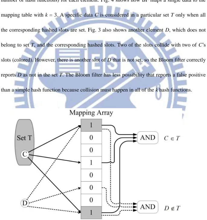
Fig. 4. The mapping mechanism of a Bloom filter (k = 3). ... 9
Fig. 5. Different data maps to same slots in mapping array. In (a), we cannot tell if a slot is mapped multiple times. In (b), we can decrease the counter to indicate removal of an element. ... 10
Fig. 6. (a) Banked Bloom filter with four hash functions. (b) Hard-wired permutation table of BBF. ... 12
Fig. 7. (a) Double layer counting Bloom filter. (b) Memory bank of the upper layer. (c) Memory bank of the lower layer (d) Permutation table. ... 16
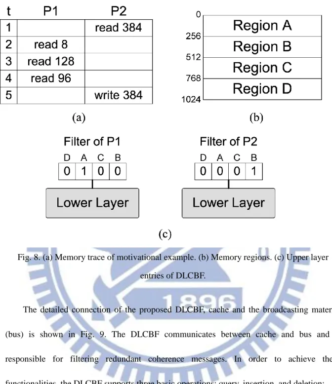
Fig. 8. (a) Memory trace of motivational example. (b) Memory regions. (c) Upper layer entries of DLCBF. ... 18
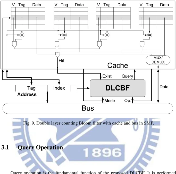
Fig. 9. Double layer counting Bloom filter with cache and bus in SMP. ... 19
Fig. 11. Filtered rate of classic Bloom filter (BF), counting Bloom filter (CBF), banked Bloom filter (BBF), and double layer counting Bloom filter (DLCBF) with simmedium
PARSEC benchmarks ... 27
Fig. 12. Energy savings introduced by BF and DLCBF ... 29
Fig. 13. Filtered rate of double layer counting Bloom filter with different data set sizes of blackscholes ... 30
Fig. 14. Filtered rate of classic Bloom filter (BF), counting Bloom filter (CBF), banked Bloom filter (BBF), and double layer counting Bloom filter (DLCBF) with simlarge PARSEC benchmarks ... 32
Fig. 15. Segmented bus architecture for 16-core processor ... 33
Fig. 16. Filtered rate of DLCBF and HPCA10 filter ... 35
Fig. 17. Filtered rate of DLCBF with different sizes of its upper layer ... 38
Fig. 18. Filtered rate of DLCBF with different sizes of its lower layer ... 40
Fig. 19. (a) The index used in the fast query layers. (b) Filtered rate of default DLCBF and TLCBFs. (c) Filtered rate of 1k-DLCBF, 2k-DLCBF and 13-13-TLCBF ... 43
Chapter 1
Introduction
In modern computing systems, multi-core architectures have become prominence due to its high performance and energy efficiency. The shared-memory Symmetric Multi-processor (SMP) is one of the widely developed multicore architectures which exchange data between cores via the shared memory space. However, data sharing among multiple cores in a SMP introduces cache coherence issues [1]. In order to maintain a coherent memory system, a shared memory SMP system needs to update or invalidate the shared data whenever one of its owners writes a new value to this data location. The broadcast-based snoopy protocol is a widely used scheme to maintain a coherent memory system. This protocol broadcasts the data sharing states on the system interconnection to trigger the distributed data management mechanisms on each processor.
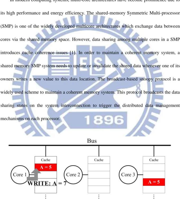
Fig. 1. A coherence mechanism when multiple cores share the same data. The colored cache blocks are shared among different cores. They should be either updated or invalidated while
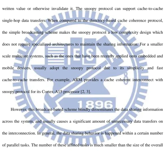
Fig. 1 illustrates a simple example of the cache coherence issue on a SMP system with three processors (Core 1 to Core 3). Assume that Core 1 and Core 3 share the same data (A=5). When Core 1 performs a write operation to its copy of the shared data (A=7), the broadcast-based snoopy protocol would update the shared copy in Core 3 with the latest written value or otherwise invalidate it. The snoopy protocol can support cache-to-cache single-hop data transfers. When compared to the directory-based cache coherence protocol, the simple broadcasting scheme makes the snoopy protocol a low complexity design which does not require specialized architectures to maintain the sharing information. For a smaller scale multicore systems, such as the ones that have been recently applied onto embedded and mobile devices, usually adopt the snoopy protocol due to its simplicity and fast cache-to-cache transfers. For example, ARM provides a cache coherent interconnect with snoopy protocol for its Cortex-A15 processor [2, 3].
However, this broadcast-based scheme blindly disseminates the data sharing information across the system, and usually causes a significant amount of unnecessary data transfers on the interconnection. In general, the data sharing behavior is happened within a certain number of parallel tasks. The number of these affined tasks is much smaller than the size of the overall multi-core system. With the broadcast-based scheme, the processors which are not involved in the current data sharing state would consequently perform needless data searches in their own caches. For example, assume that there is a datum owned by only one processor. When this particular datum is written, the snoopy protocol would broadcast an invalidation message and
invoke searches at all the caches while none of these searches are actually needed. All these redundant data management operations would occupy the system resources and degrade the performance and energy efficiency.
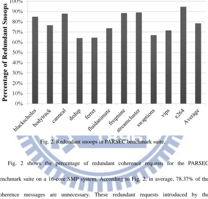
Fig. 2. Redundant snoops in PARSEC benchmark suite.
Fig. 2 shows the percentage of redundant coherence requests for the PARSEC benchmark suite on a 16-core SMP system. According to Fig. 2, in average, 78.37% of the coherence messages are unnecessary. These redundant requests introduced by the broadcasting behavior of the snoopy protocol would unnecessarily put a cache in a busy mode and increase the energy consumption. These unnecessary cache operations could even block the useful requests from processors and therefore degrade the system performance. This problem will be more severe in embedded systems due to its stringent energy constraints and
strict performance requirements. If these unnecessary data communication and cache searches can be filtered, the effective utilization of the system resources, such as cache and interconnection, can be enhanced significantly. This paper proposes a novel architecture of Double Layer Counting Bloom filter to screen out the unnecessary data management caused by the broadcast-based snoopy protocol in a SMP system.
A Bloom filter [4] is a classic unit used in database management. It uses hash functions to maintain the data mapping structure and provides an effective method to perform membership querying. However, due to the limited size of the filter, it suffers from rapid array saturation problem [5]. If the dataset of an application is too large, the data mapping structure would saturate and make the filtering mechanism ineffective. This paper proposes a novel architecture of Double Layer Counting Bloom Filter (DLCBF), which uses a two-layer filtering scheme to achieve high filtering rates with low implementation cost. The DLCBF implements an extra layer of hash function and the counting feature at each filter entry. By using the hierarchical structure of the hash function, DLCBF can manage larger query spaces and effectively increase the successful filter rates while requiring a smaller memory usage than the conventional Bloom filters. The counting feature of DLCBF further enhances the ability to handle the array saturation issue.
To demonstrate the efficacy of the proposed DLCBF, this paper implements the DLCBF on two system modules of a SMP system to reduce unnecessary data processing of the snoopy coherence protocol. The first module, depicted in Fig. 10, is the local cache of each processor.
By connecting a Bloom filter between a cache and system interconnection, the filter mechanism can be used to screen out the unnecessary snooping messages that would be otherwise handled by each processor. The second module is the hierarchical shared system bus illustrated in Fig. 15. A Bloom filter is embedded in the system interconnection to reduce the costly system-wide data broadcasting. When compared with conventional Bloom filters, the DLCBF can manage larger data set with fast data accesses while requiring smaller memory area. By deploying the DLCBF in a SMP system, a substantial amount of redundant memory operations and data transmission can be eliminated. In our experiment, the DLCBF can reduce up to 65.8% of unnecessary snoops and up to 13.17% of energy consumption to local caches with 18.75% less memory usage. Simulation results also show that the DLCBF outperforms conventional filters by 58% for local transmissions and 1.86X for remote transmissions on a hierarchical system interconnection. Furthermore, we implemented DLCBF in Verilog HDL. The RTL simulation shows that the DLCBF can achieve 1.544 ns of delay when querying and the overall area is 113,413 μm2 with 90nm technology node. In short, our contributions are:
1. We proposed a novel and area-efficient design of Double Layer Counting Bloom Filter (DLCBF), which can effectively manage a larger query space than conventional Bloom filters.
2. We have demonstrated that, on a 16-core SMP system, the DLCBF achieves 81.99% better filtering rate over all other conventional Bloom filters while costing 18.75%
less memory storage.
3. We have also demonstrated that, by removing the unnecessary data management, the DLCBF can achieve 13.17% of overall energy saving.
The rest of the paper is organized as follows. In Chapter 2, we introduce the basic architecture of a Bloom filter (BF). Two modified versions, Counting Bloom Filter (CBF) and Banked Bloom Filter (BBF), are also discussed. Furthermore, several related works are reviewed. Chapter 3 shows the proposed filter structure, Double Layer Counting Bloom Filter (DLCBF). The detail functionality and implementation concerns are also discussed. Chapter 4 covers our evaluation methodology and demonstrates the cycle accurate simulation results. Finally, we conclude this paper in Chapter 5.
Chapter 2
Preliminary
To give a general background on membership querying techniques, this chapter will first introduce a simple hash-based method. Then three types of Bloom filters will be discussed, including classic Bloom filter (BF), counting Bloom filter (CBF), and banked Bloom filter (BBF). These three Bloom filters are widely used designs and provide different advantages. The proposed DLCBF is a novel architecture which combines the features of these three filter types and benefits from all of them. Some related works are also reviewed briefly.
2.1
Previous Work on Bloom Filter Designs
2.1.1 Simple Hash-based Technique
A membership querying function returns a value of true or false to identify the existence of a given input query. A straightforward way to implement a membership query function is to give an entry to each individual member. However, the total number of the members is usually much larger than the limitation of the memory size in a design. A hash function is a basic yet efficient solution for membership querying. An input query will be sent to a hash function, and a hashed value is returned to index the corresponding entry of the query. However, the single-index hash table is prone to returning many false positives for different queries. For example, a computer system with n-bit memory addresses will introduce 2n
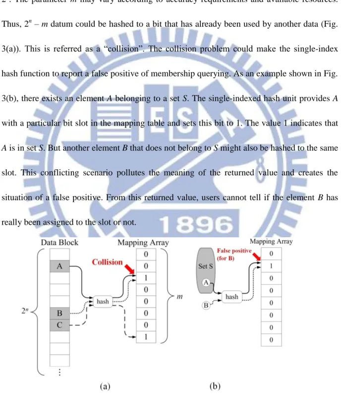
distinct memory locations. In an ideal case, a hash function needs 2n bits to distinguish each data location. But due to the storage limitation in real systems, the hash function is forced to map the 2n memory space to a mapping table with only m bits, where m is much smaller than 2n. The parameter m may vary according to accuracy requirements and available resources. Thus, 2n – m datum could be hashed to a bit that has already been used by another data (Fig. 3(a)). This is referred as a “collision”. The collision problem could make the single-index hash function to report a false positive of membership querying. As an example shown in Fig. 3(b), there exists an element A belonging to a set S. The single-indexed hash unit provides A with a particular bit slot in the mapping table and sets this bit to 1. The value 1 indicates that
A is in set S. But another element B that does not belong to S might also be hashed to the same
slot. This conflicting scenario pollutes the meaning of the returned value and creates the situation of a false positive. From this returned value, users cannot tell if the element B has really been assigned to the slot or not.
2.1.2 Classic Bloom Filter (BF)
A Bloom filter is a space-efficient data structure proposed by Bloom in the 1970s [4]. Bloom filter uses multiple hash units for each element and sets several bits (depends on k, the number of hash functions) for each element. Fig. 4 shows how BF maps a single data to the mapping table with k = 3. A specific data C is considered in a particular set T only when all the corresponding hashed slots are set. Fig. 3 also shows another element D, which does not belong to set T, and the corresponding hashed slots. Two of the slots collide with two of C’s slots (colored). However, there is another slot of D that is not set, so the Bloom filter correctly reports D as not in the set T. The Bloom filter has less possibility that reports a false positive than a simple hash function because collision must happen in all of the k hash functions.
2.1.3 Counting Bloom Filter (CBF)
Classic Bloom filter provides a memory-effective way of reducing hash collisions by using multiple hashes. However, a classic Bloom filter suffers from two problems. First, as the number of hash function increases, its mapping slot is “polluted” or “saturated” faster since the Bloom filter requires setting k bits for each element. Second, the classic Bloom filter does not support “deleting” or “resetting” the mapping slots. In other words, once a bit is set, the classic Bloom filter has no mechanism to reset it. Eventually, the classic Bloom filter will be filled up with 1’s and loses its filtering functionality.
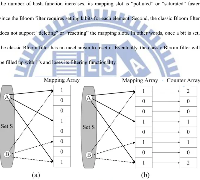
Fig. 5. Different data maps to same slots in mapping array. In (a), we cannot tell if a slot is mapped multiple times. In (b), we can decrease the counter to indicate removal of an element.
Since the multiple hash function is inevitable for Bloom filters, Fan et al. [6] proposed counting Bloom filter (CBF) to enable resetting a mapping slot. Counting Bloom filter adds an additional counter array along with the mapping slots of the classic Bloom filter. Each l-bit
counter is associated with a mapping slot in a one-to-one fashion. Whenever an element is inserted to a set, each hashed slot will increment its corresponding counter by 1 and sets the mapping slot to 1. Therefore, the counter indicates the number of elements hashed to it, as depicted in Fig. 5. On the other hand, whenever an element is removed, each slot will decrement its corresponding counter. When a counter is decreased to zero, its corresponding mapping slot will be reset to zero. With this resetting procedure, CBF achieves a lower false positive rate and hence reduces the impact of saturation of the classic Bloom filter.
2.1.4 Banked Bloom Filter (BBF)
Both BF and CBF requires k lookups from the mapping table because of k hash functions. Making these lookups in a serial manner is inefficient and difficult to meet the timing constraint in hardware implementation. However, parallelizing k lookups requires large memory bandwidth, so each memory in the filter has to implement k read/write ports for querying and updating elements. Banked Bloom filter was proposed to address the issue [7]. Similar to the banked cache access, BBF supports required bandwidth by using banking instead of adding read/write ports. Assume a memory with p ports and each port has B banks, it can provide a maximum of p∙B simultaneous access as long as no more than p operations are accessing the same bank [7].
When applying Bloom filters to the local cache or interconnection of a SMP system, the filters are usually accessed at every cycle. Therefore, a delay in the filter is undesirable.
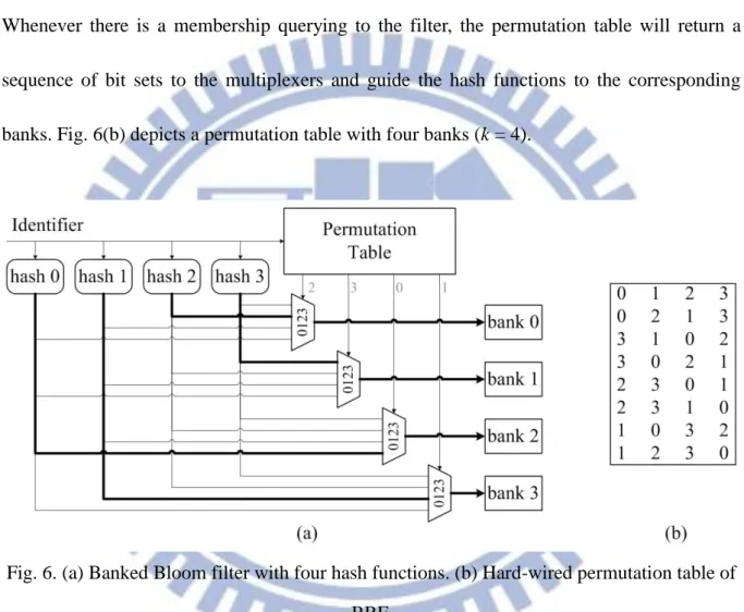
However, bank conflicts will stall the accessing procedure and make the filter to be ineffective. Banked Bloom filter uses a hard-wired permutation table to prevent bank conflicts. Fig. 6(a) shows how a banked Bloom filter is organized. With four hash functions, the BBF is configured as four banks to provide a memory bandwidth of 1×4=4 accesses simultaneously. Whenever there is a membership querying to the filter, the permutation table will return a sequence of bit sets to the multiplexers and guide the hash functions to the corresponding banks. Fig. 6(b) depicts a permutation table with four banks (k = 4).
Fig. 6. (a) Banked Bloom filter with four hash functions. (b) Hard-wired permutation table of BBF.
2.2
Related Work
In this section, we present several variants of Bloom filter designs. The major objective of these variants can be classified into three different categories: to improve the querying
speed of a Bloom filter, to reduce the memory utilization, or to lower the probability of false positive.
The two-tier Bloom filter [8] is targeted to reduce the querying time by adding a second tier cache Bloom filter. The two-tier Bloom filter will check both the filter cache and main filter simultaneously whenever query is invoked. If the querying element is cached, the faster filter cache will respond. Otherwise, the main filter will be responsible for returning a result. Segmented Bloom filter [9], on the other hand, decouples the bit vector from the counter array of a counting Bloom filter and improves the querying speed by avoiding access of the counter array. It is equipped with a duplicated hash function to enable faster outcome of a query. Whenever a query occurs, the input identifier will go through the extra hash and access the bit vector directly.
Ahmadi and Wong proposed a Bloom filter with an additional hash (BFAH) to reduce the memory utilization of a Bloom filter [10]. With the additional hash function, the BFAH stores only one out of k memory address for each element. It is no longer required to store other k-1 redundant copy. Furthermore, the additional hash function helps to distribute incoming elements uniformly. The compressed filter [11] is proposed to approach the same objective as BFAH. The compressed filter focused on optimizing the transmission size by changing the bit distribution in the filter when the Bloom filter is transferred as a network message.
is proposed. The DlBF is built on the simple idea of recording where collisions happen when inserting elements. It is able to remove an element like counting Bloom filters, but without introducing false negative issue [13]. Interval filter (IF) reduces false positives especially for transactional memory [14]. The IF views a memory interval as an element and its index is represented as the lower bound and the upper bound of the memory interval. In this way, IF is able to extract spatial locality of the memory trace and show a lower false positive probability.
Chapter 3
Double Layer Counting Bloom Filter
Both the classic Bloom filter and counting Bloom filter have difficulty of providing the high accessing bandwidth required by k hash functions. The banked Bloom filter mitigates this problem by banked memory accesses. However, all filters still pose significant storage overhead. The classic Bloom filter implements a 1-bit-per-slot, but needs a large number of slots to alleviate the array saturation issue. Although the banked Bloom filter provides large memory bandwidth, it has the same 1-bit-per-slot structure as the classic Bloom filter. The counting Bloom filter, on the other hand, can handle array saturation better than the classic Bloom filter and banked Bloom filter, but it increases the storage overhead by using multi-bit counters instead of the single set bit.
To reduce the storage overhead and further increase membership querying speed while preserving the functionality of the Bloom filter, we propose a novel Double Layer Counting Bloom Filter architecture (DLCBF). The DLCBF adopts the idea of two-tier Bloom filter [8]. By adding a second tier cache Bloom filter, the two-tier Bloom filter is able to reduce the membership querying time. Whenever a query is invoked, the two-tier filter will check both the filter cache and main filter simultaneously. If the queried element is cached, the faster filter cache will respond with either a true or a false. Otherwise, the main filter will be responsible for returning the membership querying.
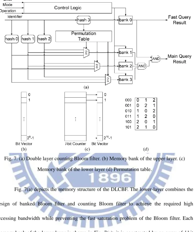
Fig. 7. (a) Double layer counting Bloom filter. (b) Memory bank of the upper layer. (c) Memory bank of the lower layer (d) Permutation table.
Fig. 7(a) depicts the memory structure of the DLCBF. The lower-layer combines the design of banked Bloom filter and counting Bloom filter to achieve the required high accessing bandwidth while preventing the fast saturation problem of the Bloom filter. Each memory bank of the lower-layer is shown in Fig. 7(c); it is constructed by an array of l-bit counter and a bit vector. The permutation table adopted from BBF is shown in Fig. 7(d). We implemented the similar design as in BBF, except the number the possible outcomes since the DLCBF only have three banks in its lower layer. While lower-layer is designed to provide higher accessing bandwidth, the upper-layer demonstrates the similar idea of the two-tier
Bloom filter. However, the proposed DLCBF differs from the two-tier Bloom filter in the utilization of the extra “tier” or “layer”. As we know, if a specific memory location is accessed, it is highly possible that the nearby locations will be accessed. This is called the spatial locality. The DLCBF introduces an extra upper layer of hash units upon a banked Bloom filter (lower layer) to catch the locality behavior. In other words, the upper layer is responsible for the membership querying for a consecutive memory region, not only for a single element. Besides, the extra hash function (hash3 in Fig. 7(a)) can generate different permutation for lower layer hash functions. Here we give a motivational example: Suppose we have a 2-core system and its memory access trace is displayed in Fig. 8(a). Fig. 8(b) shows that the whole memory space is divided into four consecutive regions. Each region has a corresponding entry in the upper layer of the double layer counting Bloom filter, as depicted in Fig. 8(c). When time t = 5, we can observe that P2 has to issue a broadcast coherence message in order to tell other processors that they have to invalidate the memory location 384. In the previous designs, such as classic Bloom filter and counting Bloom filter, filter needs to perform a full search in its storage. On the other hand, the DLCBF can show that memory location 384 is definitely not in P1 very quickly through its extra layer by identifying that the corresponding region (Region B) is not in P1. Therefore, DLCBF could reduce the member ship querying time.
Fig. 8. (a) Memory trace of motivational example. (b) Memory regions. (c) Upper layer entries of DLCBF.
The detailed connection of the proposed DLCBF, cache and the broadcasting material (bus) is shown in Fig. 9. The DLCBF communicates between cache and bus and is responsible for filtering redundant coherence messages. In order to achieve these functionalities, the DLCBF supports three basic operations: query, insertion, and deletion:
Fig. 9. Double layer counting Bloom filter with cache and bus in SMP.
3.1
Query Operation
Query operation is the fundamental function of the proposed DLCBF. It is performed whenever the snoopy coherence protocol triggers a broadcasting coherence message. The query operation also serves as the prerequisite of the deletion operation; we will give an explanation later. Every cache, except the one that issues the request, is asked to check itself if it has the requesting data. Bus will send the coherence message to both cache and the DLCBF simultaneously, in order to prevent the querying procedure from the critical path of coherence operation. The faster querying operation and the slower cache search will perform in parallel.
When DLCBF receives such coherence message from bus, it takes the memory address of the requesting data and checks the filter storage. If the requesting data is not in this cache, the DLCBF will responds false and cancel the cache search. In contrary, the DLCBF will respond true and the cache search will continue.
3.2
Insertion Operation
Whenever a data is read from main memory, the coherent bus not only sends the data and the address to cache, it also sends the address to the DLCBF at the same time. The DLCBF will set the corresponding upper layer filter entry to one, and then increase the corresponding lower layer filter entries of this data by one.
3.3
Deletion Operation
In order to keep the correct record of data, the DLCBF will remove an item whenever a data is removed from cache under the situation of cache eviction or invalidation caused by coherence protocol. However, an item deletion in DLCBF might be incorrect. Guo et al. identified the false negative problem of counting Bloom filter in [13]. Guo et al. found that the counting Bloom filter produces possible false negative results when it deletes a false positive item [13]. For example, suppose that data B is a false positive item in the filter of P2. If P2 receives a request for invalidate data B, the CBF will mistakenly reduce the value of
each corresponding entries by one. Furthermore, if one of these corresponding entries is reduced to zero, a possible false negative will occur. Our proposed DLCBF have the same problem because we adopt the similar design of the counting Bloom filter. It becomes a serious problem in snoop filtering because the false negatives will make the multicore system become incoherent. Guo et al. also proposed a novel scheme, multichoice counting Bloom filter, to lower the probability of false negatives. Although, their proposal can be applied on DLCBF, they do not guarantee a false negative free condition. Therefore, we propose another solution specifically for coherence message filtering. Since the reason of false negatives is caused by removing a false positive item, our idea is to perform an actual cache search whenever DLCBF wants to delete an item. In the scope of filtering coherence message, a deletion in DLCBF can occur only when the cache performs a writeback or invalidation. Both of the operations require a real cache search to handle the data or the coherence state, so our manipulation in the deletion will not introduce extra cache searches. As depicted in Fig. 9, DLCBF has an extra input signal labeled "Exist", which represents the result of the actual cache search. The deletion operation of DLCBF will reduce the value of corresponding filter entries only when the Exist signal responds a cache hit. Hence, we can solve the false negative problem without compromising the overall system performance and guarantees false negative free condition for coherence message filtering.
3.4
Summary
There are three main benefits enabled by DLCBF. First, DLCBF adopts the banked structure and adds an extra layer to meet the heavy memory bandwidth requirement [7] and reduce membership querying time. With multiple access banks, the DLCBF requires only one lookup for each banked memory while CBF needs k lookups with k different hash functions. Second, DLCBF takes the advantage of data locality. It separates memory space into different regions. Since data in different regions are less likely to be accessed in a consecutive way, an extra layer can filter out unnecessary data operations with higher speed. Third, DLCBF benefits from the extra permutation array, which further lowers the probability of data collision.
Chapter 4
Evaluation
This chapter first shows the experimental setup used in this paper. Then the performance of DLCBF is analyzed and compared with other Bloom filters in a SMP system. The DLCBF will be implemented on two system modules to reduce unnecessary data processing. The first module is the local cache of each processor. The DLCBF is used to reduce the unnecessary cache searches from snoopy coherence protocol. The second module is on the shared system bus to filter out the redundant data transmission. We also conducted design parameter exploration on the DLCBF design. We will show effects caused by different sizes of the upper layer and the lower layer separately and we will show several extensions to triple layer design.
4.1
Experiment Methodology
We use GEM5 [15], a full-system event-driven simulator, as our experiment platform. We use a simple in-order processor model so that we can evaluate the proposed scheme within a reasonable simulation time. Table I lists the configuration parameters we used in our simulations. A single transaction shared bus takes charge of the communication among processors. The experiments were executed with 11 representative workloads from PARSEC benchmark suite [16].
COMPONENT PARAMETERS
Processor core 2GHz, single-issue in-order
Block size 64bytes
L1 I-caches (Private) 32kB, 2-way, 2-cycle
L1 D-caches (Private) 64kB, 2-way, 2-cycle
Memory 60-cycle access latency
Bus
1GHz, single transaction, 1-cycle overhead per transaction
Table. 1 Processor and cache/memory parameters
Four types of Bloom filters were implemented and compared, including the classic Bloom filter (BF), counting Bloom filter (CBF), banked Bloom filter (BBF), and the proposed double layer counting Bloom filter (DLCBF). As depicted in Fig. 10 the Bloom filters were connected in between of caches and the shared bus. All the filters in the experiment used four hash functions. The classic Bloom filter, CBF, and BBF are implemented with 1K bytes of memory per processor core. The DLCBF uses only 0.8125K bytes per core, bringing an 18.75% of memory usage reduction. This difference is from the upper layer of memory array, which is only 25% of a standard memory array.
Fig. 10. SMP with Bloom filters
4.2
Results of Filtering Unnecessary Cache Searches
Fig. 11 shows the filtered snooping rate using classic Bloom filter, CBF, BBF, and DLCBF for each benchmark. The filtered rate represents how many snoops are screened out by the filter. These are the unnecessary snoops that do not need to be handled by a cache. The experiments were performed on multi-core systems with two, four, eight, and sixteen processors. We choose the "simmedium" data set of PARSEC benchmark suite to evaluate the proposed architecture in a reasonable time. The right most column of Fig. 11 represents the geometric mean of the filtered rates observed in the benchmarks. The reason we choose geometric mean instead of arithmetic mean is that the total number of snoops in each benchmark differs significantly and the results we show here are ratios to them. We can see that the classic Bloom filter performs poorly in all benchmarks. The reason is that the classic Bloom filter faces array saturation problem and does not support “resetting” a slot whenever an element is removed from the set. In this context, removal of an element is considered as
cache line invalidation or eviction. Therefore, its mapping array saturates even when data set size is small and the classic Bloom filter loses its filtering functionality very quickly. Banked Bloom filter suffers from the same reason, although it supports faster querying access. On the other hand, because the counting feature enables the “resetting” ability, CBF reduces the array saturation rate. With lower saturation rates, CBF achieves better filtering behavior than the classic and banked Bloom filters. When compared with a classic Bloom filter, CBF achieves up to 3.57X filtered rate improvement.
With an additional hash function and hard-wired permutation table, DLCBF divides and maps the whole memory space to several storage arrays. This design avoids the data in different memory spaces colliding with each other. Inside each storage array, DLCBF utilizes multiple hash functions to prevent collision. In addition, the counting feature enables a much lower probability of collision and the ability to reset an element more effectively. Therefore, DLCBF further improves the filtered rate and significantly outperforms the classic Bloom filter, CBF, and BBF. The average improvement of filtered rate is 81.99% and 31.36% when compared to classic Bloom filter and CBF respectively.
Another observation from Fig. 11 shows that the filtered rate increases with the number of processors for all four filters. This is because that when the number of processors increases, each processor is responsible for a smaller size of data set. For example, assume the total data set is 1MB; each processor in a 2-core multi-processor system would deal with 512kB of data. And in a 4-processor system, each core will be responsible for only 256kB of data. The
Fig. 11. Filtered rate of classic Bloom filter (BF), counting Bloom filter (CBF), banked Bloom filter (BBF), and double layer counting Bloom filter (DLCBF) with simmedium PARSEC
effective data set size allocated to each individual core decreases with the increasing number of processors. The smaller effective data set size lowers the memory space that needs to be handled by each filter. Therefore, the characteristics of each filter are improved with more processors in a system. Notice that freqmine and streamcluster do not follow the above criteria. The possible reason is that these two benchmarks might have many true-sharings or the data set is not evenly distributed among processors as in our example.
We use Synopsys design compiler and CACTI 5.3 [17] to estimate the area of the proposed double layer counting Bloom filter. Two SRAM modules with 1-Byte words and one read/write ports were modeled with CACTI to estimate the area and access time of the DLCBF. The upper layer module is modeled as a 64-Byte, single-bank SRAM module, while the lower layer is a 768-Byte SRAM. We use 2-bank architecture to estimate the lower layer module because CACTI does not support 3-bank architecture as the DLCBF. The four hash functions, permutation table, and the additional control logic are modeled with Synopsis design compiler. We implements H3 hash because it is proven better than others [18]. The overall area of DLCBF takes about 113,413 μm2 using 90nm technology and the critical path
is 1.544 ns.
CACTI is also used to give the energy saving estimation. Fig. 12 depicts the estimated energy saving percentage after applying BF and DLCBF, respectively. The energy estimation here is calculated with the energy saved by filtering unnecessary snoops subtracts the energy consumed by the filter. BF introduces more energy consumption to the system because its
filtered rate is so low that it couldn't compensate the energy consumed. DLCBF, on the other hand, benefits from its higher filtered rate and is able to contribute energy savings for most of cases. In average, the DLCBF could save up to 13.17% of energy in a SMP system.
Fig. 13. Filtered rate of double layer counting Bloom filter with different data set sizes of
blackscholes
In order to examine the scalability of the proposed design, we evaluated one of the PARSEC benchmark, blackscholes with different data sizes. As shown in Fig. 13, PARSEC provides five data set sizes for each benchmark [16]. From the smallest one to the largest are
test, simdev, simsmall, simmedium, and simlarge. The result shows that filtered rate of the
DLCBF will decrease with the size of data set. With this insight, we performed an evaluation for each benchmark with the largest data set size. These experiments were conducted on the
same multi-core system as the previous one, except that we extended the number of processors to twenty-four and thirty-two. Fig. 14 shows the filtered snooping rate for each benchmark in our evaluation. Notice that facesim does not work with medium-size data set and both facesim and fluidanimate do not support twenty-four-processor system. The bottom right most column is the geometric mean of the filtered rates. When the data set size increases, all the filters performs worse than with the medium-size benchmarks because they have to manage a larger size of data. Nevertheless, we can observe that the proposed DLCBF still outperform other designs in most of the cases. The average improvement of filtered rate in large-size benchmark is 7X and 1.1X when compared to classic Bloom filter and CBF respectively.
Fig. 14. Filtered rate of classic Bloom filter (BF), counting Bloom filter (CBF), banked Bloom filter (BBF), and double layer counting Bloom filter (DLCBF) with simlarge PARSEC
4.3
Results of Filtering Unnecessary Data Transmission on a
Shared Segmented Bus
Fig. 15. Segmented bus architecture for 16-core processor
The segmented bus is proposed as an energy-efficient, bus-based on-chip interconnection [19]. It separates a long bus into several shorter buses and organizes them in a hierarchical manner. Fig. 15 depicts a 16-core processor with the segmented bus and filter. As we know, not every coherence transaction is expected to be broadcasted to every processor. A segmented bus implements two filters, In-filter and Out-filter, at each sub-bus to maintain some knowledge of cache contents in the local and remote segments and screens out unnecessary transactions. The In-filter keeps track of cache lines that are currently in the segment. When a broadcast is invoked, every segment will first look up at its local In-filter. And a broadcast to local processors will be performed if the In-filter allows. The Out-filter keeps track of cache lines that is sent out to remote segments. If a specific cache line has never been sent before, the local segment does not broadcast it to the remote segments. Each
segmented bus filter contains two arrays of 8192 entries, one array for In-filter and the other for Out-filter. Every entry is consisted of a 10-bit counter. In all, each filter requires 20K bytes of storage overhead.
In this experiment, we apply the DLCBF to a segmented bus. We simulated a 16-processor system with a segmented bus. We compared two filter schemes. The first scheme is the Bloom filter design (HPCA10) used in [19], and the second scheme adopts the proposed DLCBF. The HPCA10 is implemented with 20kB of memory, while the DLCBF is 13kB in size. Fig. 16 shows the simulation results, DLCBF and HPCA10 [19] are compared. Basically, the HPCA10 filter is a counting Bloom filter with big counters and a large storage. The outperforming filtered rate of DLCBF confirms that the additional hash is helpful even when compared to a large CBF. The average improvement of filtered rate is 58% for In-filter and 1.86X for Out-filter in comparison to HPCA10.
4.4
DLCBF Design Parameter Exploration
In this section, we evaluated three design parameters of the proposed DLCBF. The upper layer is a fast query structure in the proposed DLCBF. We first compared the filtering performance among different sizes of upper layer filter. We also explored the effect of the lower layer. We compared the filtered rate among several sizes of the lower layer filter. Finally, we added another layer to construct a triple layer counting Bloom filter (TLCBF) and evaluated several configurations of the TLCBF.
4.4.1 Size of Upper Layer
Upper layer of the DLCBF serves as a fast query mechanism in snoop filtering. Each entry in the upper layer represents a consecutive memory region instead of a single memory location. DLCBF will check the upper layer and the lower layer simultaneously whenever a query request arrives. If the memory region corresponding to the queried memory location is not in cache, the upper layer will responds a false; otherwise, it will wait for the query result in the lower layer. To explore the influence of the upper layer, we simulated with several configurations of the upper layer while the lower layer remains the same as the default one. The default DLCBF has 512 entries in its upper layer with each entry representing one bit. The size of the default filter is 64 Bytes. We compared six different size of upper layer with the default configuration. We used the same simulation parameters listed in Table I.
Fig. 17 shows the simulation result with the PARSEC benchmark suite. The vertical axis shows the filtered rate and the horizontal axis stands for sizes of the upper layer in Bytes. In all the evaluated benchmarks, filtered rate increases with the size of upper layer. However, the improvement from 4-Byte to 256-Byte is very subtle because each memory region is too large so that the upper layer filter could hardly distinguish memory locations. Recalled the motivational example in Fig. 8, the upper layer filter can easily tell that the memory location 384 is not in P1 since the region it belongs to is not in P1 either. If we divide the whole memory space into two regions, instead of four, then the original memory region A and B are combined as one. Therefore, the upper filter of P1 will respond a true to the query of memory location 384 even if it is not in processor P1. In other words, the proposed DLCBF performs better with larger upper layer because it has a lower probability of responding false positives. The simulation result of 1k-Bytes to 16k-Bytes supports this criterion. We can observe that the filtered rate grows significantly from 256-Byte to 16k-Byte. The average improvement of filtered rate with a 16k-Byte upper layer is 1.17X compared to the default configuration (64-Byte) in sixteen-core system.
4.4.2 Size of Lower Layer
The lower layer filter is the fundamental building block of the proposed DLCBF. It adopts the idea from the banked Bloom filter and the counting Bloom filter to provide a high accessing bandwidth while not compromising the filtering performance. In the proposed DLCBF, the lower layer is constructed with three identical counter arrays and each array in the default configuration contains 512 two-bit counters. Thus, the size of default configuration of lower layer in DLCBF is 768 Bytes in total. We compared five DLCBF configurations with different sizes of lower layer to the default one.
We take the simulation parameters shown in Table I. In these experiments, the upper layer is fixed to 64 Bytes in size. The simulation result is shown in Fig 18. The horizontal axis represents sizes of the lower layer in Bytes. Intuitively, the filter rate will increase with the size of lower layer filter because the larger the size of the lower layer filter, the less the probability of hash collision will occur. However, not all the benchmarks follow this assumption. For example, dedup and ferret shows a U-shape curve and the worst filtered rate happens at the configuration with 3k Bytes of lower layer. Nevertheless, the filter rate will increase with the size of lower layer when it is larger than 3k Bytes. The reason behind this fact has not been identified yet.
4.4.3 Multiple Layer Designs
We extend the double layer counting Bloom filter by adding another layer to make it as a triple layer counting Bloom filter (TLCBF). In the double layer filter, the upper layer only takes part of the memory address (m-bit) as its querying index, so each entry represents a memory region, as depicted in Fig. 19(a). We extend this idea to the triple layer filter. The top layer and the middle layer still served as the fast query mechanism and both layers also take partial address as index. A p-q-TLCBF represents that the top layer takes the first p bits and the middle layer takes q bits address, respectively. The bottom layer of TLCBF is the same as the lower layer of DLCBF, which provides high accessing bandwidth.
FILTER
TOP LAYER MIDDLE LAYER
INDEX LENGTH (p) SIZE INDEX LENGTH (q) SIZE
5-4-TLCBF 5-bit 4 Bytes 4-bit 2 Bytes
6-3-TLCBF 6-bit 8 Bytes 3-bit 1 Bytes
7-2-TLCBF 7-bit 16 Bytes 2-bit 4 Bits
8-1-TLCBF 8-bit 32 Bytes 1-bit 2 Bits
We first evaluated four TLCBF designs that take the same nine-bit address as in the upper layer of DLCBF. Table II lists the parameter of the top layer and the middle layer in each filter. Fig. 19(b) only depicts the simulation result with a sixteen-core system because the results in two-, four-, and eight-core system have similar outcome. All four configurations of TLCBF show almost the same filtering performance and are also comparable with the proposed DLCBF. The 5-4-TLCBF is the most cost effective one among all designs because it has the smallest storage overhead. From the result of upper layer parameter exploration, we know that the difference between each configuration is very subtle when the size of upper layer is smaller than 1k Byte. Therefore, we conducted another evaluation with two DLCBFs and one TLCBF that have larger upper layer size. As shown in Fig. 19(c), the filtered rate of 13-13-TLCBF is better than 1k-DLCBF but worse than 2k-DLCBF. The 2k-DLCBF and the 13-13-TLCBF outperform the 1k-DLCBF by 13.65% and 8.09% in average, respectively. Notice that we only show the result with the sixteen-core system here. The 13-13-TLCBF uses 2k Byte in the upper layer, just as the same as the 2k-DLCBF. Therefore, the 2k-DLCBF is the more cost effective choice to increase the filtered rate. In conclusion, if the storage constraint is less than 1k Byte, then the triple layer filter will be a cost effective choice. On the other hand, if the storage constraint is relaxed to more than 1k Byte, the DLCBF with larger upper layer is the most suitable design.
(a)
(b)
(c)
Fig. 19. (a) The index used in the fast query layers. (b) Filtered rate of default DLCBF and TLCBFs. (c) Filtered rate of 1k-DLCBF, 2k-DLCBF and 13-13-TLCBF
Chapter 5
Conclusion
In this paper, we proposed an area efficient double layer architecture of Bloom filter, DLCBF. By adding extra filtering layer, DLCBF reduced the memory usage by 18.75% and achieved 81.99% and 31.36% better filtered rate when compared with a classic Bloom filter and CBF respectively. Besides, the DLCBF also demonstrated a 13.17% reduction on overall energy consumption. In this paper, The DLCBF module is implemented by using the hardware description language (Verilog) and synthesized by Synopsys’s Design Compiler. The synthesized design reports a delay time 1.544ns for each query and the overall area is 113,413 μm2. When applying on segmented bus, DLCBF outperforms HPCA10 filter by 58% for In-filter and 1.86X for Out-filter. Furthermore, according to the explored three design parameters of DLCBF: the size of upper layer, the size of lower layer, and multiple layer design, it is suggested that increasing the size of each layer would help on the filtered rate of DLCBF. The multiple layer design shows almost the same filtering performance when the size of upper layer is less than 1k Byte. When the upper layer is enlarged, the multiple layer design shows 40.73% degradation in filtering capability compared to the double layer design under the same storage constraint.
REFERENCES
[1] J. L. Hennessy, and D. A. Patterson, Computer architecture: a quantitative approach: Morgan Kaufmann Pub, 2011.
[2] ARM, “CoreLink (TM) CCI-400 cache coherent interconnect,”
http://infocenter.arm.com/help/topic/com.arm.doc.ddi0470g/DDI0470G_cci400_r1p1_trm.pdf, 2012.
[3] ARM, “Introduction to AMBA (R) 4 ACE (TM),”
http://www.arm.com/files/pdf/CacheCoherencyWhitepaper_6June2011.pdf, 2011.
[4] B. H. Bloom, “Space/time trade-offs in hash coding with allowable errors,” Commun. ACM, vol. 13, no. 7, pp. 422-426, 1970.
[5] M. Ghosh et al., “Way guard: a segmented counting bloom filter approach to reducing energy for set-associative caches,” in Proceedings of the 14th ACM/IEEE international symposium on Low power electronics and design, San Fancisco, CA, USA, 2009, pp. 165-170.
[6] L. Fan et al., “Summary cache: a scalable wide-area web cache sharing protocol,” IEEE/ACM Trans. Netw., vol. 8, no. 3, pp. 281-293, 2000.
[7] M. Breternitz et al., “A Segmented Bloom Filter Algorithm for Efficient Predictors,” in Computer Architecture and High Performance Computing, 2008. SBAC-PAD '08. 20th International Symposium on, 2008, pp. 123-130.
[8] M. Jimeno, K. J. Christensen, and A. Roginsky, “Two-tier Bloom filter to achieve faster membership testing,” Electronics Letters, vol. 44, no. 7, pp. 503-504, 2008.
[9] M. Ghosh et al., “Efficient system-on-chip energy management with a segmented bloom filter,” in Proceedings of the 19th international conference on Architecture of Computing Systems, Frankfurt, Germany, 2006, pp. 283-297.
[10] M. Ahmadi, and S. Wong, "A Memory-Optimized Bloom Filter Using an Additional Hashing Function." pp. 1-5.
[11] M. Mitzenmacher, “Compressed bloom filters,” in Proceedings of the twentieth annual ACM symposium on Principles of distributed computing, Newport, Rhode Island, United States, 2001, pp. 144-150.
[12] C. E. Rothenberg et al., “The deletable Bloom filter: a new member of the Bloom family,” Communications Letters, IEEE, vol. 14, no. 6, pp. 557-559, 2010.
[13] D. Guo et al., “False Negative Problem of Counting Bloom Filter,” Knowledge and Data Engineering, IEEE Transactions on, vol. 22, no. 5, pp. 651-664, 2010.
[14] R. Quislant et al., “Interval filter: a locality-aware alternative to bloom filters for hardware membership queries by interval classification,” in Proceedings of the 11th international conference on Intelligent data engineering and automated learning, Paisley, UK, 2010, pp. 162-169.
[15] N. Binkert et al., “The gem5 simulator,” SIGARCH Comput. Archit. News, vol. 39, no. 2, pp. 1-7, 2011.
[16] C. Bienia, “Benchmarking modern multiprocessors,” Princeton University, 2011. [17] S. Thoziyoor et al., “CACTI 5.1,” HP Labs, Palo Alto, Tech. Rep. HPL-2008-20, 2008.
[18] M. V. Ramakrishna, E. Fu, and E. Bahcekapili, “Efficient hardware hashing functions for high performance computers,” Computers, IEEE Transactions on, vol. 46, no. 12, pp. 1378-1381, 1997.
[19] A. N. Udipi, N. Muralimanohar, and R. Balasubramonian, “Towards scalable, energy-efficient, bus-based on-chip networks,” in High Performance Computer Architecture (HPCA), 2010 IEEE 16th International Symposium on, 2010, pp. 1-12.