利用電腦視覺與泛晰導航技術作室內環境自動車航行之研究
101
0
0
全文
(2) 利用電腦視覺與泛晰導航技術作室內環境自動車航行之研 究 Autonomous Vehicle Navigation in Indoor Environments by Computer Vision and Fuzzy Guidance Techniques. 研 究 生:陳逸傑. Student:Yi-Chieh Chen. 指導教授:蔡文祥. Advisor:Dr. Wen-Hsiang Tsai. 國 立 交 通 大 學 資 訊 科 學 研 究 所 碩 士 論 文. A Thesis Submitted to Institute of Computer and Information Science College of Electrical Engineering and Computer Science National Chiao Tung University in Partial Fulfillment of the Requirements for the Degree of Master in. Computer and Information Science June 2004 Hsinchu, Taiwan, Republic of China. 中華民國九十三年六月.
(3) 利用電腦視覺與泛晰導航技術作室內環境自動車航行 之研究. 研究生: 陳逸傑. 指導教授: 蔡文祥博士. 國立交通大學資訊科學研究所. 摘 要. 本論文提出了一套基於電腦視覺及泛晰控制理論的導航技術,可 讓自動車航行於室內環境中,並且具備避碰障礙物的能力。在實驗中 我們利用一可無線遙控且擷取影像的迷你自動車作為研究平台。我們 設計了一套人性化、有效而且沒有繁瑣規則與限制的學習方法,能自 動分析使用者學習時的操作行為,並自動建立導航路線地圖。在使用 此方法得到學習路線資料之後,我們也運用一套完整的導航策略來完 成學習路線之航行。此策略主要是建構在泛晰控制導航的技術之下, 並且可以搭配學習時記錄的資料,完整地走完所有的學習路線。我們 最後亦以成功的學習與導航實驗結果證明本系統的完整性與可行性。.
(4) Autonomous Vehicle Navigation in Indoor Environments by Computer Vision and Fuzzy Guidance Techniques. Student : Yi-Chieh Chen. Advisor: Dr. Wen-Hsiang Tsai. Institute of Computer and Information Science National Chiao Tung University. ABSTRACT. A vision-based fuzzy-guidance approach to autonomous vehicle navigation in indoor environments with a capability of avoiding obstacles appearing in planned paths is proposed. A small vehicle with wireless control and image grabbing capabilities is used as a test bed. A simple learning strategy is designed for flexible and effective non-visual learning of reachable spots in rooms without rules or restrictions. Through this simple learning strategy, a planned path is obtained by analyzing user-driving commands and odometer data. And following the learned path, the. vehicle. can. accomplish. specified. navigation. sessions. by. proposed. collision-avoidance strategies based on the use of fuzzy-control guidance techniques and input images acquired by an onboard vision system. And some strategies for navigation accuracy maintenance are also proposed. Finally, experimental results showing flexibility of the proposed approach for navigations in indoor environments are also included.. ii.
(5) ACKNOWLEDGEMENTS. I am in hearty appreciation of the continuous encouragement, support, and technical guidance received from my advisor, Dr. Wen-Hsiang Tsai, not only in the development of this thesis, but also in every aspect of my personal growth. Thanks are due to Mr. Yen-Chung Chiu, Mr. Nan-Kun Lo, Mr. Wei-Liang Lin, Mr. Kuei-Li Huang, Mr. Cheng-Jiun Lai, and Miss Yen-Lin Chen for their numerous discussions and suggestions. Appreciation is also given to the colleagues of the Computer Vision Laboratory in the Department of Computer and Information Science at National Chiao Tung University for their suggestions and help. I also extend my profound thanks to my family during my school life for their lasting love, support, and encouragement. I dedicate this dissertation to my parents.. iii.
(6) CONTENTS ABSTRACT (in Chinese) ........................................................................... i ABSTRACT (in English)........................................................................... ii ACKNOWLEDGEMENTS...................................................................... iii CONTENTS.............................................................................................. iv LIST OF FIGURES ................................................................................. vii LIST OF TABLES .................................................................................... ix Chapter 1 Introduction..............................................................................................1 1.1 Motivation.............................................................................................................1 1.2 Survey of Related Studies .....................................................................................2 1.3 Overview of Proposed Approach ..........................................................................3 1.4 Contributions.........................................................................................................6 1.5 Thesis Organization ..............................................................................................7 Chapter 2 System Configuration and Navigation Principles.................................8 2.1 Introduction...........................................................................................................8 2.2 System Configuration ...........................................................................................9 2.2.1 Hardware Configuration .........................................................................10 2.2.2 Software Configuration...........................................................................10 2.3 Proposed Learning Principle and Process...........................................................11 2.4 Proposed Vehicle Guidance Principle and Process .............................................13 Chapter 3 Proposed Fuzzy Guidance Techniques for Indoor Navigation ..........16 3.1 Introduction.........................................................................................................16 3.2 Review on Fuzzy Control Concepts ...................................................................17 3.3 Reasons of Using Fuzzy Guidance Techniques ..................................................19 3.4 Parameters for Proposed Fuzzy Guidance System .............................................20 3.4.1 Features for Vehicle Guidance in Rooms................................................21 3.4.2 Features for Vehicle Guidance in Corridors............................................24 3.5 Proposed Fuzzy-Control Systems and Their Uses in Guidance .........................28 3.5.1 Proposed Fuzzy Control System for Room-Type Guidance...................28 3.5.2 Proposed Fuzzy Control System for Corridor-Type Guidance...............30. iv.
(7) Chapter 4 Simple Learning Strategies for Indoor Navigation by User-Driving and Odometer Parameters ...................................................................33 4.1 Introduction.........................................................................................................33 4.2 Two Navigation Modes.......................................................................................34 4.3 Manual Learning Algorithm ...............................................................................35 4.3.1 Proposed Control Interface for manual learning.....................................36 4.3.2 Proposed Simple User-Driving Rules for Learning................................37 4.3.3 Data Structures of Learned Data.............................................................38 4.4 Automatic Path Map Creation Process of Learned Data ....................................41 4.4.1 Learned Data Analysis ..........................................................................41 4.4.2 Identification of Nodes for Single Path Mode ........................................42 4.4.3 Identification of Nodes for Area Mode...................................................45 Chapter 5 Vehicle Navigation in Indoor Environment.........................................48 5.1 Introduction.........................................................................................................48 5.2 Navigation in Single Path Mode .........................................................................49 5.2.1 Navigation Strategy for Straight-Line Sections ......................................50 5.2.2 Navigation Strategy for Turning Sections...............................................51 5.2.3 Process of Proposed Navigation in Single Path Mode............................55 5.3 Navigation in Area Mode....................................................................................56 5.3.1 Generation of essential data for path planning .......................................56 5.3.2 Dynamic Path Planning using Dijkstra Algorithm..................................60 5.3.3 Navigation Strategy among Room Nodes...............................................61 5.3.4 Process of Proposed Navigation in Area Mode ......................................63 5.4 Strategy for Fuzzy Navigation Accuracy Maintenance ......................................65 5.4.1 Comparison of Navigation Distances .....................................................65 5.4.2 Comparison of Directions .......................................................................66 5.4.3 Smooth Curve Following Process...........................................................66 5.4.4 Adjustment of Beginning Position..........................................................68 Chapter 6 Person Following in Corridors .............................................................69 6.1 Introduction.........................................................................................................69 6.2 Image Preprocessing for Unexpected Object Detection in Corridors.................70 6.3 Human Identification ..........................................................................................73 6.4 Human Tracking by Feet Positions .....................................................................74 6.5 Process of Person following................................................................................75 Chapter 7 Experimental Results and Discussions.................................................78 v.
(8) 7.1 Experimental Results ..........................................................................................78 7.1.1 Navigation in Single Path Mode.............................................................78 7.1.2 Navigation in Area Mode........................................................................79 7.2 Discussions .........................................................................................................85 Chapter 8 Conclusions and Suggestions for Future Works .................................86 8.1 Conclusions.........................................................................................................86 8.2 Suggestions for Future Works.............................................................................87 References…………………………………………………………………………...89. vi.
(9) LIST OF FIGURES Figure 1.1 : Flowchart of four stages of proposed system…………………………….6 Figure 2.1 : The Amigo vehicle used in this study…………………………………….9 Figure 2.2 : Structure of proposed system……………………………………………11 Figure 2.3 : Illustration of the proposed learning process……………………………13 Figure 2.4 : An illustration of vehicle navigation process……………………………15 Figure 3.1 : Illustration of a fuzzy inference system…………………………………18 Figure 3.2 : An image of an obstacle appearing in navigation path………………….20 Figure 3.3 : Illustration of image processing results (a) An input image. (b) Result of candidate route point classification. (c) Result of route area extraction. (d) Result of guidance line computation. (e) Another input image. (f) Result of guidance line computation of (e)…………………………….………24 Figure 3.4 : Illustration of image processing results (a) An input image. (b) Result of binarization process. (c) Result of applying Sobel operator to (b). (d) Result of finding connected components. (e) An another input image. (f) Result of applying binarization process and Sobel operator to (e)…..…27 Figure 3.5 : Membership functions for guidance in rooms…………………………..30 Figure 3.6 : Membership functions for guidance in corridors……………………….32 Figure 4.1 : An illustration of the proposed user control interface…………………..37 Figure 4.2 : An illustration of the learned data………………………………………40 Figure 4.3 : An example to illustrate a created graph for single path mode…………44 Figure 4.4 : An example to illustrate created graph for area mode…………………..47 Figure 5.1 : An illustration of computing two wheel speeds for the case of turning rightward in curve following……………………………………………53 Figure 5.2 : A figure illustrating curve following process……………………………53 Figure 5.3 : A figure illustrating the check process before curve following process (a) A case that the curve following process can be executed (b) A case that the curve following process can not be executed……………………….54 Figure 5.4 : A figure to illustrate a process of proposed navigation procedure in single path mode……………………………………………………………….57 Figure 5.5 : An example to illustrate result of performing the proposed algorithm….59 Figure 5.6 : An illustrative example to show the direction creation of two turn nodes, where 1 represents node N-1 and 2 represents node N0………………….63 Figure 5.7 : A figure to illustrate proposed navigation process in the area mode……64 Figure 5.8 : An example to illustrate the usability of smooth curve following for navigation accuracy maintenance……………………………………….67 vii.
(10) Figure 6.1 : Images of several image processing results (a) A corridor image. (b) An unexpected object is appeared. (c) Binary thresholding of (b). (d) Two approximation lines are found. (e) Scan the lines vertically from bottom to the approximation lines. (f) An Object Foot is found (yellow points). (g) Another example. (h) Two Object Foots are found……………………..72 Figure 6.2 : An example to illustrate the position of tracking target…………………75 Figure 6.3 : A process of person following…………………………………………..77 Figure 7.1 : An experimental result of navigation in single path mode……………...81 Figure 7.2 : An experimental result in area mode (1)………………………………...82 Figure 7.3 : An experimental result in area mode (2)………………………………...83 Figure 7.4 : An experimental result in area mode (3)………………………………...84. viii.
(11) LIST OF TABLES Table 1 : User-Driving commands and parameters for Learned Data………………..40. ix.
(12) Chapter 1 Introduction. 1.1 Motivation Recently, vision-based autonomous vehicles or mobile robots have been used in more and more human environments, especially in security patrolling and home service applications. A difficulty encountered in such vehicle navigation applications is the complicated environment faced by an autonomous vehicle, resulting in a challenge of designing a general and flexible learning strategy for various navigation environments. Facing this challenge, we use a small vehicle with wireless control and image grabbing capabilities as a test bed for the development of indoor navigation in this study. Most former works focused on vision-based learning. Though this approach is useful for constructing visual environment data, which can be used for locating a vehicle in the navigation stage, yet certain restrictions are usually imposed on the learning process, resulting in inconvenience or difficulty in conducting the learning work. Furthermore, certain artificial landmarks or specific scene features are often forced to appear in the environment to be learned, in order to accomplish the work of locating the vehicle by landmark or feature matching in the navigation stage. This often makes the learning method inapplicable or less flexible in certain applications. Finally, landmark or feature matching often yields imprecise vehicle location results, leading possibly to unstable navigation performances. In this study, we propose a 1.
(13) non-visual approach to learning which solves all the above-mentioned problems encountered in the conventional vision-based learning approach. After the learning process is finished, the remaining task is to guide the vehicle to navigate along the learned path safely. That is, two goals must be achieved, one is that the vehicle should traverse along the learned path correctly, and the other is that it should avoid possible obstacles appearing in the path. Therefore, we propose to use fuzzy-control techniques to guide the vehicle and avoid possible collisions in the meanwhile. Navigation accuracy maintenance is also considered. With these capabilities, the vehicle can be used in many applications, such as security patrolling, inter-building transportation, cleaning service among rooms, intelligent toys, and so on.. 1.2 Survey of Related Studies In many applications for vehicle navigation in indoor environments, learning navigation paths is required before a navigation process can be started. Since scenes of indoor environments are often complicated and may consist of several kinds of rooms and corridors, such learning works are usually difficult and heuristic. Design of general learning algorithms for complicated indoor environments is still a difficult research topic. In Davison and Murray [1], some preset landmarks placed manually are used to train a mobile robot or vehicle to recognize its location. After a few times of training, the vehicle can detect the landmarks accurately and follow them to finish the learned path stably. In Hayet, Lerasle, and Devy [2], a vehicle was designed to identify obvious square blocks as landmarks and recorded its color and size as feature. 2.
(14) sets in the learning stage. Then the vehicle can check the color and the size of each landmark to locate its position in the navigation stage. In Gaussier, Joulain, and Zrehen [3], a mobile robot can be controlled by visual information retrieved from particular goal landmarks. And their model does not need a precise map nor learn all the possible positions in the environment. Besides, many visual navigation methods have been developed in recent years. In Li and Tsai [4], a graph-based navigation method was proposed. The vehicle traverses among the nodes in a graph which is composed of learned paths. But certain complex learning rules were adopted to the learning process. In [5, 6], route areas in the navigation path are obtained and the vehicle keeps navigating on the central path of each route area. In Desouza and Kak [7], a survey of visual navigation techniques for mobile robots is given. Some techniques including optical flows, landmarks tracking, simultaneous localization and map-building, and visual feature matching for indoor or outdoor environments were introduced. Cho and Nam [8] proposed a method of vision-based navigation for mobile robots using fuzzy-logic control techniques. They used the wavelet transform to detect the edges of guidelines or obstacles as fuzzy input parameters and found fuzzy output parameters to guide the robot to move forward. And a collision avoidance algorithm was also proposed. Ayanna and Edward [9] proposed a technique using real-time terrain feature analysis for outdoor-environment navigation with a mobile robot. They used terrain features as fuzzy inputs to get crisp fuzzy outputs to move the robot to navigate within terrains safely.. 1.3 Overview of Proposed Approach 3.
(15) In this study, we try to design a vision-based vehicle navigation method which uses fuzzy-control guidance techniques in indoor environments. With this purpose, a simple and flexible learning method that processes user-driving parameters and odometer data automatically is proposed. Secondly, a fuzzy-control guidance technique with obstacle avoidance capability is also proposed. Finally, a person following application by tracking human feet positions is proposed. More specifically, in a system designed in this study using these proposed techniques, the following tasks are conducted: (1). Configure the setting of the parameters of a small vehicle as a test. (2). Design a fuzzy control system for the guidance purpose (3). Analyze images grabbed by the vision system of the vehicle to obtain visual parameters as fuzzy input. (4). Record user-driving parameters and odometer data during the learning process. (5). Process roughly recorded data and transform them into usable data for navigation. (6). Guide the vehicle to traverse along learned paths safely. (7). Detect human feet in corridors. (8). Track human feet to follow their movement. The proposed approach for vision-based vehicle navigation consists roughly of four stages. The first stage is Fuzzy-Control Guidance. Since the principle of fuzzy theory is intuitive and experiential, we utilize the characteristic of fuzzy theory to implement the guidance of navigation. We propose two fuzzy control systems for guiding the vehicle to move forward and avoid possible collisions. The second stage is path learning for navigation by user control. In this stage, the vehicle is controlled to move to desired places through a designed user interface. During the path learning process, a sequence of user-control actions, called user-driving parameters, and 4.
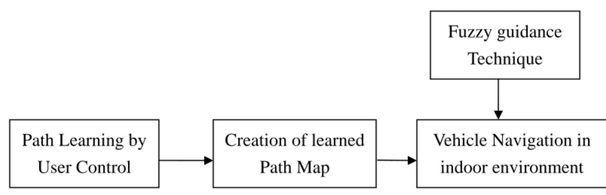
(16) odometer data are recorded, respectively. These two types of parameters will be recorded as a temporary list for the processing of the next stage. The third stage is creation of learned path map for navigation. In this stage, the parameters recorded in the previous stage will be automatically processed into a path map by the proposed path map creation process. The path map is in a form of graph, and is composed of a set of nodes connected with inter-node edges. The data of each node in the path map are recorded into a text file orderly. Then the data of this text file is a basis for autonomous navigation in the next stage. The fourth stage is vehicle navigation in indoor environments. In this stage, the vehicle traverses along the learned path node by node orderly in accordance with node data in the text file. Two navigation modes are also proposed for different purposes. One is the single path mode for one path navigation from a starting point to an ending point; the other is the area mode for navigation among rooms. And two strategies are proposed for a vehicle to navigate in indoor environments. The first is line following, which is useful for the vehicle to navigate in straight-line sections. And the second strategy is smooth curve following, which is used for turning the vehicle leftward of leftward in turning sections. Furthermore, a navigation accuracy maintenance strategy is also proposed. A possible application of the proposed approach is person following in corridors. In this application, an image processing technique is employed for detecting objects in corridors. And a human identification method by a position checking method is proposed. Since the positions of human feet are known, the person following action will be triggered for tracking the positions of human feet. In summary, an innovative learning strategy with simple and flexible capabilities without using a video camera is proposed. The vehicle can use a path map acquired by the simple learning process to navigate in desired environments. And the proposed 5.
(17) fuzzy-control guidance technique is utilized in autonomous navigation method. Using these hybrid techniques, the vehicle can navigate in any unknown indoor environment if the learning process was finished before.. Fuzzy guidance Technique. Path Learning by User Control. Creation of learned Path Map. Vehicle Navigation in indoor environment. Figure 1.1 Flowchart of four stages of proposed system.. 1.4 Contributions The main contributions of this study are summarized in the following. (1) A fuzzy guidance technique using 2D visual parameters is proposed (2) A simple and flexible learning strategy using user-driving parameters and odometer data is proposed. (3) A path map creation method which transforms rough learned data into a path map for navigation is designed. (4) A graph-based navigation method using node data in the path map is proposed. (5) A curve following method which can reduce accumulative errors for navigation is proposed.. 6.
(18) (6) Two kinds of navigation modes that can be applied in many applications are designed. (7) A person following method for tracking the positions of human feet is proposed.. 1.5 Thesis Organization The remainder of this thesis is organized as follows. The system configuration of the vehicle used as a test bed and the principles of learning and navigation are described in Chapter 2. The proposed fuzzy-control techniques and the designed fuzzy control system are described in Chapter 3. In Chapter 4, the proposed innovative learning strategy with simple and flexible capabilities, and the proposed path map creation method are described. In Chapter 5, the proposed vehicle navigation method with obstacle avoidance capability, a smooth curve following process for turning sections, and some strategies for navigation accuracy maintenance are described. The application of person following in corridors by tracking the positions of human feet is described. Satisfactory experimental results are shown in Chapter 7. Finally, some conclusions and suggestions for future works are given in Chapter 8.. 7.
(19) Chapter 2 System Configuration and Navigation Principles. 2.1 Introduction Recently, the applications of indoor navigation of mobile robots or autonomous vehicles become more and more popular, especially in home services and security patrolling. Hence, the size of the vehicle was designed to be smaller and smaller in order to achieve the purpose of dexterous movement in indoor environments. With this goal, a small vehicle with wireless control and image grabbing capabilities is used as a test bed for our research and development in this study. Because of the dexterous property of this small vehicle, it can be used in many kinds of applications. In order to navigate in any unknown indoor environment, a learning process is essential for the vehicle. Therefore, a simple and flexible learning strategy which learns user-driving parameters and odometer data is developed in this study. Through the learning process, desired navigation paths can be learned by the vehicle and useful data are recorded at in the mean time. After navigation paths are known by the vehicle after the learning process, a fuzzy-control guidance technique and a vehicle navigation method, both deigned in this study, are applied for the vehicle to navigate along the learned paths to finish desired trips.. 8.
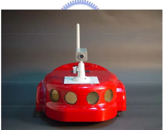
(20) 2.2 System Configuration In this study, we use the Amigo robot, a mini-vehicle made by ActivMedia Robotics Technologies Inc., as shown in Figure 2.1 as the test bed. There are eight ultrasonic sensors, an odometer, and a wireless 2.4G camera on this mobile vehicle. The ultrasonic sensors are disabled in this study because they are useless for our research work. The maximum advance speed and rotation speed of the vehicle are 75 cm/sec and 300 degrees/sec, respectively, and the speed encoders encodes 39000 ticks per wheel revolution with 124 ticks per mm. The length, width, and height with the camera and the body of the Amigo vehicle are 33 cm, 28cm, and 21cm, respectively.. Figure 2.1 The Amigo vehicle used in this study.. 9.
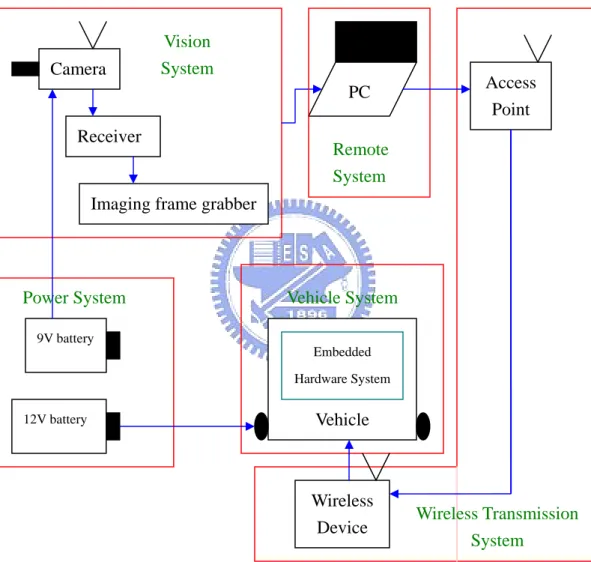
(21) 2.2.1 Hardware Configuration The proposed system is composed of five parts, as shown in Figure 2.2. The first part is the vehicle with an embedded control system. By a user’s commands , this system can control the two DC motors to move forward or backward or turn around, and return some status parameters of the vehicle to the user. The second part is a vision system which consists of a camera with a wireless transceiver, a wireless video signal receiver, and an imaging frame grabber. Because the signal obtained from the camera and sent to the video signal receiver is analog, a still digital image can be obtained by the imaging frame. The image grabbed in our experiments are of the resolution of 320×240 pixels for the reason of raising image processing efficiency. The third part is a power system which consists of two kinds of batteries. One is a 9V battery to supply the power of the wireless camera; and the other is a 12V battery to supply the power of the vehicle system. The fourth part is a remote control system in a desktop computer or a notebook PC. The kernel program can be executed on this remote control system to command the vehicle through a wireless transmission system, which is the fifth part of the proposed system, consisting of a wireless access point and a wireless signal receiver. The command of the remote control system is transmitted to the wireless signal receiver on the vehicle by an access point that meets the 802.11b standard.. 2.2.2 Software Configuration In order to transmit commands to the vehicle and to retrieve status data about the vehicle, we use the ARIA which is a C++ based open-source development environments and provides a robust interface to the vehicle. Lowest-level details or. 10.
(22) information of the vehicle (e.g., odometer data) can be easily retrieved by means of the ARIA, and moving commands can be sent by means of the ARIA also. In other words, any developer can use the ARIA as an interface to communicate with the embedded system of the vehicle. And we use the Borland C++ builder as the development tool in our experiments.. Camera. Vision System. Access Point. PC Receiver. Remote System. Imaging frame grabber. Power System. Vehicle System. 9V battery Embedded Hardware System. Vehicle. 12V battery. Wireless Device. Wireless Transmission System. Figure 2.2 Structure of proposed system.. 2.3 Proposed Learning Principle and Process 11.
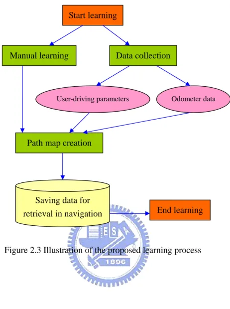
(23) To navigate in an unknown environment, learning is necessary. Then, it is desired to develop an efficient learning strategy that can learn the knowledge of desired navigation paths. Nevertheless, in most developed learning strategies, visual environment features are the most important data that are used as the basis for localization or other purposes in navigation. Even though the knowledge of visual environments data is very useful, the processes for obtaining and analyzing these visual data are usually complicated. Therefore, we want to design a learning strategy without using visual data. The proposed learning strategy consists of three processes: a user-control process, a data-collection process, and a data-transformation process. The user-control process is designed to control the vehicle to learn desired paths. Users can press the buttons on a graphic user interface designed in this study at will to accomplish the learning session. As soon as the user-control process is executed by the user, the data-collection process is activated. Two types of data are collected orderly in the process, one being user-driving parameter, and the other odometer data. The former is a set of parameters collected upon the user’ actions in controlling the vehicle. And the latter is the odometer data which include the global vehicle coordinates and azimuths of the vehicle. In addition, the path map creation process is activated after both of the user-control process and the data-collection process are finished. The collected data are then transformed into a simple graph with two types of rules, and this simple graph represents the learned path. The data of each node in the simple graph is recorded as an order list and saved into a text file for use in navigation sessions. An illustration of the learning process is shown in Figure 2.3.. 12.
(24) Start learning. Manual learning. Data collection. User-driving parameters. Odometer data. Path map creation. Saving data for retrieval in navigation. End learning. Figure 2.3 Illustration of the proposed learning process. 2.4 Proposed Vehicle Guidance Principle and Process The scene in each kind of indoor environment is different and usually complicated, and furniture and decorations within rooms also have difference appearances. Therefore, it is hard to differentiate between obstacles and non-obstacles in guiding the vehicle to correct and safe paths. Hence, a fuzzy-control guidance technique is proposed in this study which guides the vehicle in a natural manner. In every navigation cycle, a suitable steering angle can be obtained by this fuzzy-control 13.
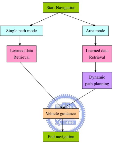
(25) guidance technique and the goal of obstacle avoidance can be achieved in the meanwhile. In other words, the proposed fuzzy-control guidance technique can nominally reduce the complexity of scenes in indoor environments for choosing a suitable path to navigate. Furthermore, a vehicle navigation process with two navigation modes for different purposes is proposed. One is the single path mode for navigating along a learned path with only a starting point and a destination. In the single path mode, the learned data are retrieved from a saved file first, and all the nodes within this navigation path are set in accordance with the nodes in the learned graph exactly. Then the navigation trip can be accomplished by traversing each node in the learned graph orderly. For this reason, two navigation strategies are proposed for the vehicle to navigate in two types of sections during the navigation process. The first strategy is used along each straight-line section between two nodes connected with a line approximately. And the second strategy is used for turning sections where the vehicle navigates around a corner. The other mode is the area mode for navigating among multiple nodes collected from several paths. In the area mode, a desired navigation path may not be learned before. First, the learned data are retrieved from a saved file, too. After that, the desired navigation path is determined by a given starting point and a given destination which are learned in the learning process. The nodes within this navigation path are found dynamically using Dijkstra shortest path searching algorithm. After the desired navigation path is determined, a similar navigation strategy is adopted for traversing along the nodes along the navigation path. An illustration of the vehicle navigation process is shown in Figure 2.4.. 14.
(26) Start Navigation. Single path mode. Area mode. Learned data Retrieval. Learned data Retrieval. Dynamic path planning. Vehicle guidance. End navigation. Figure 2.4 An illustration of vehicle navigation process. 15.
(27) Chapter 3 Proposed Fuzzy Guidance Techniques for Indoor Navigation. 3.1 Introduction In order to guide a small vehicle to navigate in indoor environments with complicated scenes, two fuzzy-control guidance techniques are proposed in this study for safe indoor navigation. Since the principle of fuzzy control is intuitive and experiential, we utilize fuzzy-guidance techniques for vehicle navigation. The essence of this approach is to keep equilibrium between navigation accuracy and fuzzy control. Generally speaking, fuzzy theory can be implemented in a wide variety of fields because of its multidisciplinary nature. A system based on a fuzzy will react to triggered events autonomously in an intuitive way. Due to this characteristic of fuzzy theory, many researchers use fuzzy theory in robot-control applications. A review of the fuzzy-control concept will be described in Section 3.2. And the reason of using fuzzy-control techniques for guidance of small vehicles in this study will be described in Section 3.3. Besides, some parameters for the proposed fuzzy model must be acquired through some image processing works. Since appearances of different kinds of indoor environments can be classified roughly into two types, namely, room and corridor, two processes of parameter acquirement for the two types of indoor environments are. 16.
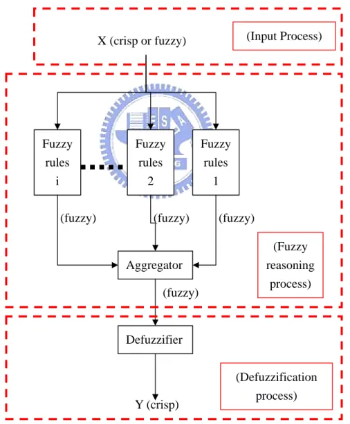
(28) proposed and will be described in Section 3.4. After necessary parameters are acquired, desired fuzzy outputs as meaningful commands for vehicle control can be obtained by a computation process based on the proposed fuzzy model. Similarly to the need of two parameter acquirement processes, two different fuzzy models are designed for vehicle guidance in the two types of indoor environments. The details of the fuzzy models will be described in Section 3.5.. 3.2 Review on Fuzzy Control Concepts The proposed fuzzy control system is derived from fuzzy inference techniques using fuzzy if-then rules and fuzzy reasoning. According to C.T. Sun [20], the basic structure of a fuzzy inference system consists of three conceptual components: a rule base, which contains the detailed fuzzy rules; a database, which defines the membership functions used in the fuzzy rules; and a reasoning mechanism, which performs the fuzzy reasoning process using the rules and certain given facts to obtain a reasonable output. In a fuzzy inference system, when fuzzy or crisp inputs are taken into the system, the outputs are fuzzy sets in most cases. But fuzzy-set outputs are not suitable for use in our vehicle control system. Therefore, a method of defuzzification is needed to extract a crisp value which best represents a fuzzy set. Besides, in the case with crisp inputs and outputs, the fuzzy inference system just implements a nonlinear mapping from its input space to its output space. And this mapping is accomplished by a number of fuzzy if-then rules, each of which describes the local behavior of the 17.
(29) mapping. The proposed fuzzy control techniques belong to this case. The procedure of a fuzzy inference system with a crisp output is shown in Figure 3.1. The first part is an input process which takes some fuzzy or crisp values as inputs into this system. And the second part is a fuzzy reasoning process which processes the inputs with fuzzy rules to yield fuzzy-set outputs. The third part is a defuzzification process which transforms the output fuzzy sets into a single crisp value. The final crisp value will be used as the basis for generating commands to guide the vehicle in the proposed fuzzy guidance techniques.. (Input Process). X (crisp or fuzzy). Fuzzy rules i (fuzzy). Fuzzy rules 2 (fuzzy). Aggregator (fuzzy). Fuzzy rules 1 (fuzzy) (Fuzzy reasoning process). Defuzzifier. Y (crisp). (Defuzzification process). Figure 3.1 Illustration of a fuzzy inference system.. 18.
(30) 3.3 Reasons of Using Fuzzy Guidance Techniques The reason for using fuzzy guidance techniques in this study is three-fold, as described in the following. 1.. To reduce the complexity of guidance in indoor environments. Since the scene structures of indoor environments are usually complicated, it is. generally difficult to guide a vehicle to navigate in it. One way to solve this problem is to use fuzzy guidance techniques, which presumably are more proper for use to find vehicle navigation paths. That is, it expected that complicated scene structures will not influence vehicle guidance when fuzzy guidance techniques are employed. 2.. To create obstacle avoidance capability for the vehicle. When a vehicle is navigating in indoor environments using the proposed fuzzy. guidance techniques, obstacles may appear in the navigation path. An example of images grabbed by the wireless camera in our vehicle system is shown in Figure 3.1. Obstacles are regarded in this study as furniture in indoor environments or simply as part of environments because of the use of fuzzy guidance techniques. Therefore, our method for finding safe navigation paths is simple with no necessity to differentiate between objects in navigation paths and furniture or walls in environments. In the situation shown in Figure 3.1, the vehicle is steered to the left side in our experiment to avoid possible collision by considering the paper box as part of the environments instead of as an obstacle. 3.. To create an adaptive capability for the proposed vehicle system to navigate in different indoor environments. 19.
(31) Some vehicle systems use visual environments features (e. g., baseline, corner, manual landmark, etc.) in the guidance process. Since these kinds of visual features can be found only in common indoor environments, these vehicle navigation systems are useless when navigating in certain environments with no such visual feature. This weakness will not be found in our navigation system using the proposed fuzzy guidance techniques because any kind of object will be regarded as part of the environment. Therefore, the proposed vehicle navigation system can be used in any kind of indoor environments without any restriction on the scene structures of the navigation environments.. Figure 3.2 An image of an obstacle appearing in navigation path.. 3.4 Parameters for Proposed Fuzzy Guidance System According to the review on fuzzy-control concepts in Section 3.2, in order to 20.
(32) acquire a crisp output value, certain crisp values must be taken into consideration in the fuzzy guidance system first. And these crisp values are related to the designed fuzzy rules which are determined in the phase of fuzzy model development. In the proposed fuzzy guidance techniques, still images captured from the wireless camera will be processed to obtain appropriate features as crisp inputs for the fuzzy guidance system in every navigation cycle. And the proposed processes of parameter acquirement for use as inputs to the proposed fuzzy models will be detailed in the following. Because two different fuzzy guidance techniques are designed in this study, two different processes, as mentioned previously, which acquire the demanded parameters for the two fuzzy guidance techniques, are proposed. They are described in Sections 3.4.1 and 3.4.2, respectively.. 3.4.1 Features for Vehicle Guidance in Rooms In every navigation cycle, an input image captured with the wireless camera is processed to obtain two kinds of features, namely, collision-free direction, and degrees of collisions of the left and the right route sides. The values of these features are taken as inputs into the proposed fuzzy guidance system, which yields an angle as the output for use to steer the vehicle in each navigation cycle. In the following, we describe how we extract the two kinds of features by image processing techniques in the captured images. A.. Computing collision-free direction The feature of collision-free direction means the direction into which the vehicle. may be driven with no collision with the objects along the path traversed by the. 21.
(33) vehicle. Such a feature is computed in every navigation cycle in the following way. First, we divide an input image into 4×4 blocks and classify each image block into two classes, namely, route area and non-route one. As a preliminary step to achieve this goal, we utilize an algorithm presented in Li and Tsai [6] to locate image blocks of possible route areas. The essence of the algorithm is to use two pixel features, namely, a pixel’s grayscale value and its Sobel edge value, to identify candidate route-area pixels. A pixel in the input image with its grayscale value close to a pre-learned grayscale value of the room ground and with its Sobel edge value smaller than a pre-selected threshold is classified as a candidate route-area pixel. An example of such image pixel classification results is shown in Figs. 3.3(a) and 3.3(b). Because of color and uniformity similarities, some wall or furniture regions may be misclassified as route areas, as can be seen in the example shown in Fig. 3.3(b). Nevertheless, we propose an algorithm in this study to remove such erroneous areas in the following, which in addition computes the above-mentioned feature of collision-free direction from the remaining correct route areas in the input image. Algorithm 1. Computation of route areas and collision-free direction. Step 1.. Perform region growing to find as the desired route area the largest bottom region in the candidate route-area pixels extracted from the input image using [6]. (The region growing result of the above example is shown in Fig. 3.3(c).). Step 2.. Put two parallel horizontal scanning lines in a fixed lower part of the route area. If any non-route area crosses either scanning line and cuts it into several line segments, pick out the longest segment and call it a non-obstacle segment; otherwise, select the original scanning line as the non-obstacle segment. (At the end of this step, two non-obstacle segments 22.
(34) will be obtained.) Step 3.. Find the middle points of the two non-obstacle segments, connect them to form a line segment, and call it route segment. (The found middle points for the above example are A and B as shown in Fig. 3.3(c).). Step 4.. Compute the middle point of the route segment, and call it route center. (The result of this step for the last example is point C in Fig. 3.3(c).). Step 5.. Connect the route center to the middle point of the bottom line of the image. to form a line segment, and call it guidance line (like the line labeled L in Fig. 3.3(d).) Step 6.. Find as the desired collision-free direction θg the angle of the guidance line with respect to the bottom line of the image.. In the above algorithm, no complicated 3D computer vision technique is used in computing the collision-free direction, as contrasted with most conventional methods. Also, notice that by the above algorithm, the vehicle automatically has the capability of obstacle avoidance. Actually, obstacles in the path are treated as outside-path objects (like furniture) in this study. B.. Computation of degrees of collisions The degrees of collisions of the left and the right route sides are defined and. computed in this section. We first define a rectangular window in each captured image with two sub-windows separated by a centerline, as shown in Fig. 3.3(e). A region in each rectangular window of captured images represents an area which is two meters in front of the small vehicle. Then the proportion of the route area in the left sub-window is defined to be the degree of collision of the left route side, which will be denoted by PL. And that of the right route side can be defined similarly, and will be denoted by PR. 23.
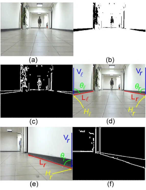
(35) Figure 3.3 Illustration of image processing results (a) An input image. (b) Result of candidate route point classification. (c) Result of route area extraction. (d) Result of guidance line computation. (e) Another input image. (f) Result of guidance line computation of (e).. 3.4.2 Features for Vehicle Guidance in Corridors The demanded features for the fuzzy guidance system for the corridor type of 24.
(36) indoor environments are different from those used for the room type. Two kinds of features, namely, baseline angle at the right side or at the left side, and baseline height at the right side or at the left side, are computed by processing an input image captured with the wireless camera in every navigation cycle. These features are taken as inputs into the fuzzy guidance system, which yields an angle as the output for use to steer the vehicle in each navigation cycle. In the following, we describe how we extract the two kinds of features by image processing techniques in captured images for use in vehicle guidance. A.. Computing baseline angle at right side or at left side The feature of baseline angle either at the left or the right side means the angle. between the lower edge of the baseline and the left or right image boundary in the captured image in every navigation cycle. Since baselines are more common in building corridors, we utilize their visual characteristics in the field of view of the camera on the vehicle to adjust the vehicle’s moving direction in the navigation process. We propose an algorithm to compute the value of the baseline angle feature at either side in the input image in the following. Algorithm 2. Computation of baseline angle at either side. Step 1.. Convert the input image into a binary image with a threshold Tb that is defined in advance. (The result of the above example is shown in Fig. 3.4(b).). Step 2.. Apply the Sobel operator to the processed binary image to find all edges in the input image. (The result of the above example is shown in Fig. 3.4(c).). Step 3.. Find the point of the lower edge of the baseline intersecting the image boundary at either side, and find the other end point of the baseline in the. 25.
(37) image using a connected component computation method [21]. Step 4.. Calculate the line equations of the two edges (upper and lower), denoted as Lr and Ll, of the baseline at either side according to the two points found in the last step. Denote also the two vertical image boundaries as Vr and Vl . (The result of the above example is shown in Fig. 3.4(d) and (e).). Step 5.. Calculate the angle between Lr and Vr, and that between Ll and Vl, and denote them as θr and θl, which are the desired features as inputs to the fuzzy guidance system. (The result of the above example is shown in Fig. 3.4(d) and (e).). In the above algorithm, we use conventional image processing techniques to compute the two baseline angles. It is pointed out here that the two baselines are not both seen at every navigation cycle, because the direction of the vehicle may be directed to the left or right side. Therefore, a reasonable assumption is made in advance, that is, if no baseline angle can be found due to failure of finding the baseline, then the baseline angle is set to 90 degrees. B.. Computing baseline height at right or left side The feature of baseline height means the y image coordinate value of the start. point of each baseline in the input image, as shown in Figs. 3.4(d) and 3.4(e). This y coordinate value can be obtained easily by performing Steps 1 through 3 of Algorithm 2. The baseline height at the right side will be denoted by Hr, while that at the left side by Hl. Generally speaking, the value of the baseline height is larger when the direction of the vehicle tends to the right or left wall, and on the contrary, the value is smaller when the direction of the vehicle tends to the midway of the corridor.. 26.
(38) Figure 3.4 Illustration of image processing results (a) An input image. (b) Result of binarization process. (c) Result of applying Sobel operator to (b). (d) Result of finding connected components. (e) An another input image. (f) Result of applying binarization process and Sobel operator.. 27.
(39) 3.5 Proposed Fuzzy-Control Systems and Their Uses in Guidance After the demanded features described in Section 3.4 are acquired, the input process of the fuzzy control system is finished and the next process is started. In the following, the fuzzy reasoning process that consists of fuzzy rule design, fuzzy aggregation, and defuzzification will be discussed. Because of the difference between the previously-mentioned two indoor environments types, two different fuzzy reasoning processes and their respective defuzzification processes are designed in this study and will be detailed in Section 3.5.1 and Section 3.5.2, respectively.. 3.5.1 Proposed Fuzzy Control System for Room-Type Guidance In the proposed fuzzy control system, when an acquired feature is processed, a steering angle θsi is computed for use in turning the vehicle in the ith navigation cycle. If θsi is positive, it means that the vehicle should turn leftward for the angle of θsi; if. θsi is negative, it means that the vehicle should turn rightward for θsi. The proposed fuzzy control system is based on two fuzzy rules in terms of three linguistic variables LESS, LEFT, and RIGHT that describe the values of the input features. The rules are described as follows: Rule 1: if the collision-free direction θg trends to LEFT and the degree of collision of the right route side PR is LESS, then turn the vehicle rightward for the. 28.
(40) angle of θsi; Rule 2: if θg trends to RIGHT and PL is LESS, then turn the vehicle leftward for. θsi. To implement the above two rules, six membership functions µ LEFT (θ g ) , µ RIGHT (θ g ) ,. (. µ LESS − R (PR ) , µ LESS − L (PL ) , µ f 1 θ S i. ),. and µ f 2 (θ S i. ). are defined as shown in Fig. 3.5, in. which the units of θg, and PR and PL are degree and percentage, respectively. The fire strengths of Rules 1 and 2 can be calculated accordingly as follows:. m1 = µ LEFT (θ g ) ∧ µ LESS − R (PR ) ; m2 = µ RIGHT (θ g ) ∧ µ LESS − L (PL ) , where ∧ denotes the AND operator which is defined as the minimum function. After the fuzzification stage, the conclusion of each rule can be derived according to fuzzy reasoning. Because the membership function of the conclusion of each rule is monotonic, the Tsukamoto defuzzification method [7] can be applied to the fuzzy reasoning process here. The crisp output θsi, which is the desired steering angle, is calculated by the following equation:. ∑ m µθ (m ) 2. θS = i. −1. j. j. j =1. j. S. 2. ∑m j =1. j. where mk is the firing strength of Rule k, and µθ−1 (m j ) is the inverse function of j. S. µθ. (θ ). The previous discussion results have been followed to design a fuzzy i. j S. S. guidance algorithm in this study. The details are omitted.. 29.
(41) µθ −LEFT(θg ). µ LESS. 1. −L. (PR ). ( ). µ f θSi 1. 1. 1. θg. 20. 50. 90. -45. PR. θsi. (a) Rule 1. µθ −RIGHT(θ g ). µ LESS. 1. 1. -20. θg. −R. (PL ). (. µ f θSi 2. ). 1 50. 90. PL. 45. θsi. (b) Rule 2. Figure 3.5 Membership functions for guidance in rooms.. 3.5.2 Proposed Fuzzy Control System for Corridor-Type Guidance In contrast with the fuzzy control system for the room type described above, the fuzzy control system for the corridor type is different in fuzzy rules and input features. The steering angle θsi is an output of the fuzzy control system in the ith navigation cycle, which is the same as the condition of room-type guidance. If θsi is positive, it means that the vehicle should turn leftward for the angle of θsi; if θsi is negative, it means that the vehicle should turn rightward for θsi. The proposed fuzzy control system is based on two fuzzy rules in terms of two linguistic variables, LARGE and SMALL, that describe the values of the input features. The rules are described as follows: 30.
(42) Rule 3: if the baseline angle θl is SMALL and the baseline height at the left side Hl is LARGE, then turn the vehicle rightward for the angle of θsi; Rule 4: if θr is SMALL and Hr is LARGE, then turn the vehicle leftward for θsi. To implement the above two rules, six membership functions µ SMALL− R (θ r ) , µ SMALL − L (θ l ) , µ LARGE − R (H r ) , µ LARGE − L (H l ) , µ f 3 (θ S i. ), and. (. µ f 4 θSi. ). are defined as shown in. Fig. 3.6, in which the units of θr and θl, and Hr and Hl are degree and integer, respectively.. The fire strengths of Rules 3 and 4 can be calculated accordingly as follows:. m3 = µ SMALL− L (θ l ) ∧ µ LARGE − L (H l ) ; m4 = µ SMALL − R (θ r ) ∧ µ LARGE − R (H r ) , where ∧ denotes the AND operator defined again as the minimum function. After the fuzzification stage, the conclusion of each rule can be derived according to fuzzy reasoning. Because the membership function of the conclusion of each rule is monotonic, the Tsukamoto defuzzification method again can be applied to the fuzzy reasoning here. The crisp output θsi, which is the desired steering angle, is calculated by the following equation:. ∑ m µθ (m ) 4. θS = i. −1. j. j. j =3. j. S. 4. ∑m j =3. j. where mk is the firing strength of Rule k, and µθ−1 (m j ) is the inverse function of j. S. µθ. (θ ). The previous discussion results have been followed to design a fuzzy i. j S. S. 31.
(43) guidance algorithm in this study. The details are omitted here.. µ LARGE − L (H l ). µ SMALL − L (θ l ). 1. µ. 90. S. 1. 1. 45 65. (θ ) i. f3. θl. 120 215 240 Hl. 30. θsi. 90. (a) Rule 3.. ( ). µ LARGE − R (H r ). µ SMALL − R θ r. 1. µ. 90. θl. (θ. i S. 1. 1. 45 65. f4. 120 215 240 Hl. -90 -30. (b) Rule 4.. Figure 3.6 Membership functions for guidance in corridors.. 32. θsi. ).
(44) Chapter 4 Simple Learning Strategies for Indoor Navigation by User-Driving and Odometer Parameters. 4.1 Introduction In this chapter, we propose a non-visual approach to learning which solves all the problems encountered in the conventional vision-based learning approach. This non-visual learning process is just a sequence of free actions of vehicle driving without using a vision system. The vehicle is driven by the user from one room spot to another as wished. Only simple data consisting of the records of user-driving actions as well as the odometer values of each spot visited along traversed paths are collected. To achieve this goal of simple learning process, we design a convenient user-control interface and simple user-driving rules, and these will be described in Section 4.2. After the manual learning process is finished, an automatic transformation method is proposed for creating path maps with the learned data as input. The generated path map consists of a set of connected nodes, with each inter-node edge being a traversed trajectory in the learning process. Since the navigation process is classified into two modes, namely Single path mode and Area mode, we also propose two kinds of path creation processes for this purpose. In the path creation process for 33.
(45) each navigation mode, we propose an algorithm for identifying two types of path nodes, check node and turn node, in the path data collected in the manual learning process to create a path map of the visited room spots in the form of a graph with undirected edges specifying the navigated routes. The details of the automatic path map creation processes in the single path mode and the area mode are described in Section 4.3.. 4.2 Two Navigation Modes Two navigation modes are designed, which are aimed to fit the vehicle for different applications. One is the single path mode, the other the area mode. Since the characters and functions of each navigation mode are so different, the details of each navigation mode are also different, as described in the following. The single path mode means that only one navigation path is learned in the manual learning process, and the vehicle just complies with the processed data of the learned path to navigate along this path exactly. This navigation mode is applicable to applications where only one-way unceasing navigation is required. For instance, in certain kinds of “security patrolling” applications, an autonomous vehicle system is requested to navigate along a fixed path in a building. For this reason, the autonomous vehicle system can be controlled to learn a single path in advance, and then it can navigate along this learned path back-and-forth automatically, instead of hiring a security officer to guard the building. An important characteristic of the single path mode for the vehicle is that it can accomplish its navigation works autonomously without issuing any user command during the navigation process.. 34.
(46) The area mode means that multiple navigation paths are learned in the manual learning process, and the vehicle can choose a shortest navigation path dynamically according to a pair of “start point” and “end point,” which is given by the user. This navigation mode is applicable to applications where “flexible point-to-point” navigation is required. For instance, in certain kinds of “home service” applications, an autonomous vehicle system might be requested to navigate among rooms to accomplish some service works (e. g., morning calls or article transportations). Nevertheless, to learn all the routes among these rooms sometimes is too much for a vehicle (e. g., there are total 60 routes among five rooms). Therefore, we design the area mode for navigation to solve this problem. In the proposed manual learning process for the area mode, the number of necessary learned paths is the same as the number of rooms that the user wants the vehicle to visit. And in the navigation stage, according to the proposed navigation strategy for the area mode with the corresponding learned data, the vehicle will choose a shortest path dynamically to navigate among any two rooms after a user-defined command is ordered. In short, the complexity of the manual learning process can be reduced significantly by using the area mode learning process for navigation.. 4.3 Manual Learning Algorithm Some schemes are proposed in this study to accomplish the manual learning process by a user. For a user to control the vehicle easily and correctly, a plain control interface and certain simple control rules are designed. Furthermore, when a user is controlling the vehicle to learn a desired navigation path, some employed features. 35.
(47) consisting of the user-driving actions and the odometers data are collected by the proposed system and stored into three types for later processing. Besides, the vision system on the vehicle is disabled during the learning process, because the proposed learning algorithm is non-visual and uses no landmark or special features for vehicle location in the navigation environment.. 4.3.1 Proposed Control Interface for Manual Learning Since the main concept of the proposed learning strategy is simple, we hope the implementation of the proposed learning algorithm can be used for general users, even for those who do not know much about computer techniques. As a result, a plain control interface is designed for this purpose, as shown in Fig 4.1. Every user can drive the vehicle through this simple control interface to learn a desired navigation path. In the following, illustrations of this control interface will be described. Firstly, the user can press “move forward” or “move backward” to control the vehicle to move a straight line until the “stop” button is pressed. Either the user can adjust the “angle scroll bar” to a suitable position followed by pressing the “turn leftward” or “turn rightward” to turn the vehicle for a desired angle. In the single path mode, the user can utilize only the above-mentioned control actions to move the vehicle to learn the desired path easily. In addition, in the area mode two works should be done by the user. Firstly, before starting the learning process, the user must define a certain location as a start point and bring the vehicle to this start point. Secondly, when a one-way learning is finished at a room spot, the user must attach a certain description for this end place as. 36.
(48) a label. This work can be done also on the simple control interface by entering a text description in a corresponding field and pressing the “attach” button. Followed by the label attaching action, the user must bring the vehicle back to the start point. After that, the user needs to press the “another trip” button to start another one-way learning, or press the “end” button to finish the learning session in the area mode.. Figure 4.1 An illustration of the proposed user control interface.. 4.3.2 Proposed Simple User-Driving Rules for Learning Generally speaking, a learning interface is an important part of the learning. 37.
(49) system because it will affect the pleasure of a user operating the system. Nevertheless, a set of effective learning rules without complicated restrictions is another important part of the learning system. Only the use of a combination of a simple user learning interface and a set of simple user learning rules can achieve the goal of simple learning. In the following, some simple user driving rules proposed in this study for learning will be described. (1) Control the vehicle to move on the ground in indoor environments, and keep at least 50 centimeters or more to the left- or to the right-side obstacle (e. g., a piece of furniture or anything else). (2) When the distance between the vehicle and its front object is approximately smaller than 1 meter, stop the vehicle and turn rightward or leftward. (3) When the user wants to turn rightward or leftward and the vehicle is still moving, stop the vehicle right away. (4) Issue only necessary commands and avoid changing actions all the time.. 4.3.3 Data Structures of Learned Data During the previously-mentioned manual driving step in the learning stage, the proposed system allows a user to control the vehicle to move freely in an unknown environment through the simple control interface. And certain data about the learning process are recorded for later processing. All the recorded data are call learned data, and it can be classified into three types of data structure, namely user-driving actions, odometer values, and user-defined data. The detail of these data structures will be described as follows. A user-driving action means an action that is requested by the user by pressing a corresponding button on the user control interface in a learning process, including the 38.
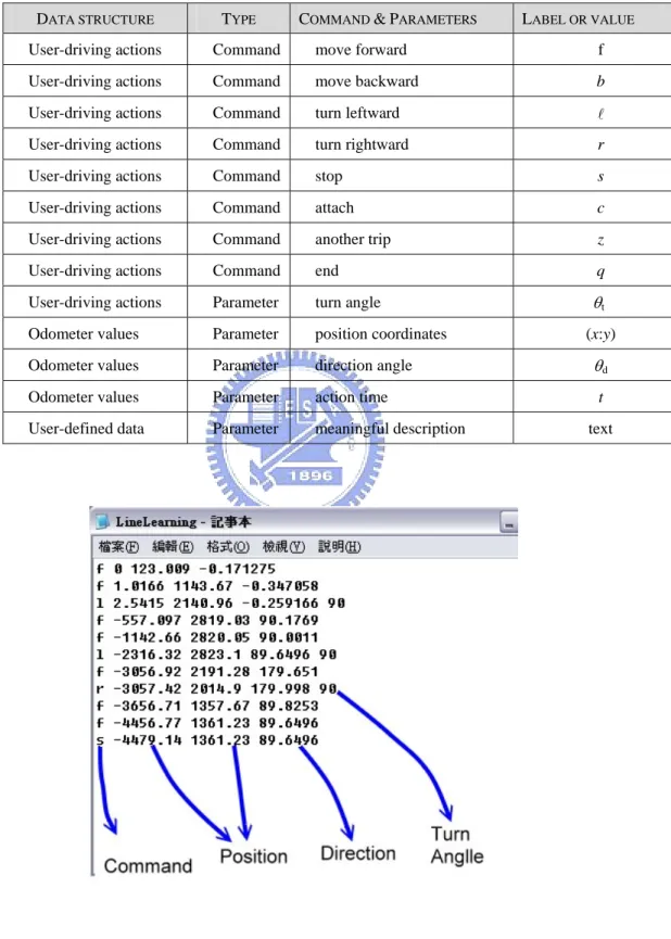
(50) “move forward”, “move backward”, “move leftward”, “move rightward”, “stop”, “attach”, “another trip”, and “end”. Each action taken by the user is recorded as a command together with its execution time with respect to the start time of the learning process. A list of the labels for data representing the user-driving actions is shown in Table 4.1. And the location of the vehicle, including its position and direction, is recorded every fixed time period (say, every second). The position data consists of the x-axis values and y-axis values for the global coordinate system (GCS), and the range of the direction data is about 360 degrees. These location data of the vehicle are called odometer values which are retrieved from the embedded system on the vehicle through the ARIA API. A list of the labels for data representing the odometer values is also shown in Table 4.1. The remaining data structure is user-defined data which represent information of corresponding room spots in area-mode learning. Each set of user-defined data is composed of one or two meaningful texts or several ones given by the user at will. But even if the number of meaningful texts is more than one, they will be regarded as a single set of user-defined data at each room spot. Furthermore, each recorded command is associated with three or four parameters. More specifically, either of the “turn leftward” or the “turn rightward” command is associated with the parameters of turn angle, position coordinates, direction angle, and action time; and each of the “move forward”, the “move backward”, and the “stop” command with the parameters of position coordinates, direction angle, and action time (without the turn angle). An illustrative example is shown in Figure 4.2.. 39.
(51) TABLE 1 USER-DRIVING COMMANDS AND PARAMETERS FOR LEARNED DATA DATA STRUCTURE. TYPE. COMMAND & PARAMETERS. LABEL OR VALUE. User-driving actions. Command. move forward. f. User-driving actions. Command. move backward. b. User-driving actions. Command. turn leftward. l. User-driving actions. Command. turn rightward. r. User-driving actions. Command. stop. s. User-driving actions. Command. attach. c. User-driving actions. Command. another trip. z. User-driving actions. Command. end. q. User-driving actions. Parameter. turn angle. θt. Odometer values. Parameter. position coordinates. Odometer values. Parameter. direction angle. θd. Odometer values. Parameter. action time. t. User-defined data. Parameter. meaningful description. Figure 4.2 An illustration of the learned data.. 40. (x:y). text.
(52) 4.4 Automatic Path Map Creation Process of Learned data After the manual learning process is finished, the learned data are recorded as a list. Although this list of learned data collects all the features about user-driving information, it cannot be used for the navigation process directly. The reason is that these learned data are too high-level for the vehicle, it needs more detail data about the learned path (e.g. global coordinates data). Therefore, in this section, certain transformation algorithms are proposed and applied to perform the path map creation process automatically. This path map creation process transforms the high-level learned data into a simple graph which consists of a set of connected nodes, with each inter-node edge representing a traversed trajectory. Then, the vehicle can use this low-level processed data with user-commands to navigate in the learned environment.. 4.4.1 Learned Data Analysis In essence, the proposed automatic path map creation process uses certain rules to analyze the simple learned data that consist of user-driving actions, odometer data, and user-defined data, which are the only information about the learned path. And we want to use a simple graph to represent the final result of the path map creation process, because a elementary graph with certain inter-node information is clear for the vehicle can accomplish a given navigation task by traversing each inter-node in the graph. Therefore, a critical job of the path map creation process is to identify each inter-node edge with its attached data in the elementary graph. In the following, the principle of this job will be described. 41.
(53) We think of the user-driving actions as useful information in the learned data for determining the location of each inter-node edge. Each user-driving action has its corresponding action time, and since the location of the vehicle is recorded every fixed time period, then we can determine the location relatively where the user-driving action is commanded. By using this transformation concept, the majority of all inter-nodes can be determined automatically. Nevertheless, a problem is encountered followed by this concept that must be solved. In certain cases, a time period between two user-driving actions is too long, so the distance between these two determined inter-nodes may be too long, and this kind of case is not suitable for navigation. Therefore, a function need be designed for the path map creation process that can automatically determines more inter-nodes with suitable locations among any two inter-nodes with too-far distance. As the location of each inter-node edge is determined, the attached data of these inter-node edge can be also determined by other inputted learned data, odometer values and user-defined data. After that, a more integrated simple graph is created by the accomplishment of path map creation process. More details of the proposed algorithm will be described in the next two sections.. 4.4.2 Identification of Nodes for Single Path Mode With the difference between two proposed navigation modes, as mentioned previously, two kinds of path map creation processes are proposed to create its corresponding simple graph. Here, the proposed automatic path map creation process for the single path mode is described, which is designed to create a graph composed of two kinds of nodes, check node and turn node, from the learned data. The meaning of a check node is to check relevant information when the vehicle arrives at this node 42.
(54) during navigation. And the meaning of a turn node is to launch or end a turning session when the vehicle arrives at this node during navigation. An algorithm is proposed as follows for this purpose.. Algorithm 1. Automatic path map creation process for single path mode. Step 1. Take the learned data as input, and identify check nodes and turn nodes by processing the commands sequentially in the input in the following way. Let the currently processed command be denoted as C0, the previously processed one as C−1, and the next processed one as C+1. Step 1.1. If C0 is ‘move forward’, then a. if C−1 is ‘turn leftward’ or ‘turn rightward,’ then create a turn node at the spot visited by the vehicle three seconds after the action time of C0 (i.e., three seconds after C0 was executed); b. if C+1 is executed at a spot farther than a meter from C0, then create check nodes at spots with distance intervals of one meter with C0 as the first created check node. Step 1.2. If C0 is ‘stop’, then if the C+1 is ‘turn leftward’ or ‘turn rightward’, then create a turn node at a spot visited by the vehicle three seconds before the action time of C0 (i.e., three seconds before C0 was executed); otherwise, create a check node at C0. Step 2. Repeat Step 1 until all commands in the input are processed. Step 3. Mark the first produced node as a start point with its corresponding location kept. Step 4. Mark the last produced node as an end point with its corresponding location 43.
(55) kept.. In the above algorithm, the two threshold values of three seconds and one meter may be varied to meet other application needs. It can be seen from the algorithm that the resulting path map is a simple attributed directed graph, which we found sufficient for this study. An example to illustrate this graph is shown in Figure 4.3.. Figure 4.3 An example to illustrate a created graph for single path mode.. 44.
數據
+7


相關文件
BayesTyping1 can tolerate sequencing errors, wh ich are introduced by the PacBio sequencing tec hnology, and noise reads, which are introduced by false barcode identi cations to
With λ selected by the universal rule, our stochastic volatility model (1)–(3) can be seen as a functional data generating process in the sense that it leads to an estimated
Abstract—We propose a multi-segment approximation method to design a CMOS current-mode hyperbolic tangent sigmoid function with high accuracy and wide input dynamic range.. The
Because of path planning and refuge activity for a community shelter will cause disaster increasing and result second disaster, hence it has a great relationship between refuge
Thus, the proposed approach is a feasible and effective method for process parameter optimization in MIMO plastic injection molding and can result in significant quality and
Writing texts to convey information, ideas, personal experiences and opinions on familiar topics with elaboration. Writing texts to convey information, ideas, personal
Writing texts to convey simple information, ideas, personal experiences and opinions on familiar topics with some elaboration. Writing texts to convey information, ideas,
Taking second-order cone optimization and complementarity problems for example, there have proposed many ef- fective solution methods, including the interior point methods [1, 2, 3,
