1
渦輪機葉片尾流控制之實驗與計算探討
Study of Wake Control for Turbomachinery Blades (1/3)
計劃編號:NSC 88-2212-E-002 -060
執行期限:87 年 8 月 1 日至 88 年 7 月 31 日
主持人:胡文聰 國立台灣大學應用力學研究所
一、中文摘要 本文以實驗探討軸流壓縮機內非定常 流場中,利用轉子尾緣噴氣來控制轉子尾 流,找出其對定子葉片的影響。主要的實 驗設備為一低速大型軸流式壓縮機,在轉 子葉片定量噴氣(30m/s)、不同的轉子 定 子葉片列軸間距、不同負載(設計點、高 負載)下對單級轉子與定子間之非定常流 場進行速度以及定子葉片受力的量測。欲 進行此一實驗,吾人得先發展出一特殊之 噴氣轉子葉片,此一轉子葉片的噴氣均勻 程度,對 整個實 驗的結 果有決 定性的 影 響。由於渦輪機轉子葉片很薄,因此想要 在渦輪機轉子葉片內部埋置流道及管路, 需經由特殊的設計及加工。更重要的是, 吾人希望噴氣葉片在距離葉片尾緣10%弦 長處,能有一均勻的速度分布,欲達到此 一均勻的速度分布,吾人發展出一微調技 術,藉此調整葉片噴氣速度分布的均勻程 度。 關鍵詞: 軸流壓縮機、流場控制、葉片尾緣 噴氣。 AbstractThis works aims to perform a series of experimental studies on flow control in a low-speed, large-scale, axial flow compressor. Specifically, air will be ejected from the rotor blade trailing edge in an attempt to interact with the stator downstream. Measurement will be made on the rotor wake with and without flow ejection, as well as the unsteady force on the stator. Due to the thinness of the rotor blade, the first year effort was mainly on
overcoming the tremendous difficulty in obtaining an uniform ejected flow at 10% chord downstream of the rotor trailing edge. Various designs were attempted and the final version uses embedded tubes within the blade and ejected flow was also fine tuned using a special technique. Results show an acceptable uniform ejected flow.
Keywords: axial compressor, flow control, trailing edge flow ejection.
二、緣由與目的 研究背景與動機 為了增進渦輪機葉片的壽命,研究減 少壓縮機葉片上的非定常受力是相當重要 的 (Figs. 1 and 2)。根據研究顯示,壓縮機 葉片上的非定常受力(unsteady loading)主 要的來源有二:勢流擾動及渦流擾動。勢 流擾動是由於轉子與定子葉片間相對運動 造成的結果,是一種沒有受到黏性的影 響。渦流的擾動起因於葉片表面黏性的作 用,使葉片表面生成邊界層延葉片尾緣離 開時形成尾流(wake flow)。當定子葉片 週期性地受到來自轉子葉片尾流帶來的非 定常受力,以及轉子與定子葉片間因相對 運動而產生的非定常勢流擾動,終會使得 定子葉片發生疲勞的現象,且若當這些非 定常負荷之頻率與葉片的共振頻率一致 時,會加速葉片的損壞甚至斷裂。於是吾 人針對轉子尾流所帶來的非定常受力做為 研究的方向,並利用轉子尾緣的葉片噴 氣,以期能改善渦流引起的定子葉片非定 常受力。此一結果對於研究壓縮機內非定 常之流場對葉片的壽命有助益,且能夠降
2 低渦輪機引擎機械性的故障率,對於飛航 安全亦能有所貢獻。 研究目標 在渦輪機內部的流場為一複雜三維非 定常的流場。由於渦流及勢流效應的交互 作用,無論在任何的軸間距下,非定常受 力渦流效應都顯得十分重要。所以為了對 渦流效應的變化更加的有掌握,於是乎吾 人發展出轉子葉片定量、均勻的噴氣方 式,以期能夠更有效的掌控轉子尾流,並 訂出一套噴氣葉片設計的方法,使得葉片 噴氣的速度分布在葉片尾緣 10%弦長處能 夠均勻,並將針對葉片定量噴氣、不同負 載下於不同的葉片軸向間距列之間,量測 軸向間距間流場速度的改變以及定子葉片 非定常受力的情形來探討渦流擾動、噴氣 葉片控制尾流與非定常流場之關聯性。並 從渦流與勢流的觀點來探討尾流的特性以 及它們如何主導葉片所承受之非定常受 力。 三、研究方法 葉片設計步驟 首先我們先從噴氣葉片的流道部分著 手,吾人利用黏土來模擬真實的葉片流 道,測試結果有下列 4 種較佳的型式,如 圖,吾人稱之為: I. 儲氣槽式 II. 導流板式 III.全管式 IV. 半管半流道式
(I) (II)
(III) (IV)
其優缺點表列如下: 優點 缺點 儲 氣 槽 式 • 設計簡單 • 加工容易 • 傷 及 葉 片 主幹 • 無 法 進 行 流速微調 導 流 板 式 • 設計簡單 • 可 得 較 均 勻 之 速 度 分布 • 加工不易 • 無 法 進 行 流速微調 全管式 • 加工容易 • 可 進 行 流 速微調 • 速 度 分 布 差異性大 • 微調不易 半 管 半 流道式 • 速 度 分 布 均勻 • 可 進 行 流 速微調 • 不易加工 綜合各種流道型式的優缺點,吾人決 定採用半管半流道式(IV),來進行轉子葉 片的加工。 其中所謂的「速度微調」,其原理簡 述如下:我們知道當流體流過一管路時, 會有壓力降,此一壓力降與雷諾數、管子 的幾何形狀及管面的相對粗糙度有關, 由管內流的理論,吾人可知 P∆ = 2 5 2 8 D Q fL π ρ3 ,且雷諾數 Re= µ ρ DV = D Q πν 4 ,由上列式子, 我們可以初估壓力降( P∆ )與管長(L)及管 徑(D)間,有一次冪的關係,亦即管徑愈 細,管子欲長,壓力降愈大。
我們可以朝此一方向來作噴氣葉片的 速度微調。在一轉子葉片中,吾人埋設 17 根的細鋼管,其長度均相同,可利用葉片 根部的管長來判定管子所在位置,並利用 細微的膠管,套上葉片根部的鋼管,利用 膠管長度對出口噴氣速度進行微調,以期 能達到出口噴氣均勻。 實驗方式 吾人利用小尺度的全壓管,於噴氣葉 片出口量取全壓,藉此找出噴氣速度。 由白努力方程式: P =t Patm+ 2 2 1 V ρ V = ρ ) ( 2 Pt −Patm 我們於葉片尾緣 10%弦長處作量測,並對葉 片內的細鋼管進行微調的動作。
在
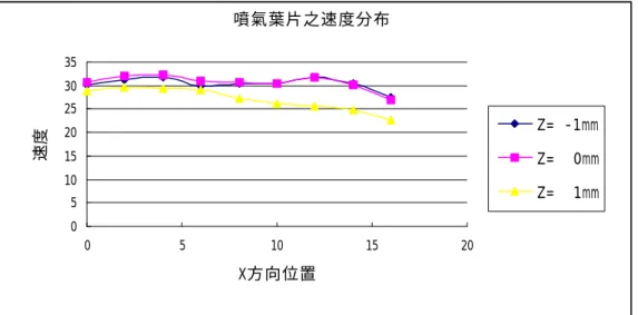
此吾人 想要強調的是,噴氣轉子葉片的製作,是 為了要調整渦輪機轉子的尾流,使得定子 葉片的非定常受力能夠降低。 此為一 X-Y 平面之流場,而吾人的轉 子噴氣測試區域在 Y-Z 平面上,且其寬度 為 20mm,足以勝任在 X-Y 平面上,2-D 問 題的噴氣模擬,至於均勻的噴氣速度我們 將其訂為 30±5 m/s,作為調整的依據。空氣壓縮機於葉片噴氣一段時間後, 壓力會下降,為了使量測結果更具代表 性,吾人僅在葉片噴氣截面上(即 Y-Z 平面 上),量測點,以作為判定均勻程度的依 據,其位置為 Z 方向上 10 點,點和點之間 距離為 2mm,每個 Z 位置在 Y 方向上 3 點, 點和點之間的距離為 1mm,至於為何要量測 一平面而非一直線的速度分布,乃是因為 噴氣出口實為一曲線,若只做一直線速度 分布的量測,恐有失真之虞,是以吾人作 一平面之量測。 四、結論 1. 噴氣葉片於轉子葉片下游 10%弦長處 速度分布欲達均勻實為不易,若不用 特殊的方法來進行微調,很難達到均 勻。 2. 想要取得一穩定氣源,以期在測試期 間不要有過大的壓力降,需使用特殊 的儲氣槽,才能達到效果。 3. 由實驗結果 Fig. 3 及 Fig. 4,可以看 出,在不同的截面上,會具有不同的 噴流速度,但其速度分布的走向,趨 勢一致,確實也得到一蠻均勻的結 果。 4. 當轉子尾流加上轉子噴氣,可得一較 均勻的尾流流向定子,可預期的,定 子非定常受力將能夠受到控制。 五、參考文獻
Hsu, S.T. and Wo, A.M., 1998, “Reduction of Unsteady Blade Loading by Beneficial Use of Vortical and Potential Disturbances in an Axial Compressor with Rotor Clocking,” ASME J. of Turbomachinery, Vol. 120, No. 4, pp.
705-713.
2 Fig. 1 The Axial Compressor Research
Facility used to test the rotor/stator configuration.
Fig. 2 Rotor/stator configuration at time
t/T= 0.0; rotor trailing edge is axially upstream of the stator leading edge. Direction of positive stator force, normal to chord, is also shown.
噴氣葉片速度分布 0 5 10 15 20 25 30 35 0 5 10 15 20 X方向位置 速度 Z= -1mm Z= 0mm Z= 1mm
Fig. 3 The velocity distribution of Blade 1 at 0.1% chord aft of trailing edge. 噴氣葉片之速度分布 0 5 10 15 20 25 30 35 0 5 10 15 20 X方向位置 速度 Z= -1mm Z= 0mm Z= 1mm
Fig.4 The velocity distribution of Blade 2 at 0.1% chord aft of trailing edge.