1002 IEEE PHOTONICS TECHNOLOGY LETTERS, VOL. 19, NO. 13, JULY 1, 2007
Study of Gamma-Irradiation Damage in LiNbO
3
Waveguides
Cheng-Chih Lai, Chin-Yu Chang, Yuan-Yaw Wei, and Way-Seen Wang
Abstract—Transmission characteristics of gamma-irradiated LiNbO3 waveguides, made by five different methods, are mea-sured and studied. All samples were irradiated with a dosage of 800 krad/h to a total amount of 10 Mrad. With the increasing gamma-irradiation intensity, the annealed proton-exchange waveguide shows the most anti-irradiative ability and the lowest transmission loss, where the measurements were carried out at a wavelength of 633 nm in a harsh gamma-irradiative environment. Index Terms—Annealed proton-exchange (APE), Gamma ray irradiation, waveguide.
I. INTRODUCTION
N
UCLEAR plants and man-made satellites show a growing interest in the possibilities offered by photonic tech-nology [1]. To apply an optical guidewave devices system in a gamma-ray environment, several research groups have shown interest in and have studied the time evolution of phys-ical and chemphys-ical characteristics under the high-energy ion irradiation [2]–[6]. The effect of radiation on an optical fiber causes an increasing of transmission loss as a fiber sensor, and similar situations happen in optical waveguide devices. For the electrooptical photonic devices, the LiNbO wave-guide coupler is one of the most important components, and the modulation efficiency of the LiNbO modulator controls the transmission bandwidth and quality. Several kinds of optical waveguide processes have been studied and utilized in modern photonics devices [7], [8]. Taylor has reviewed most of what is known about radiation effects on LiNbO in both bulk and titanium-diffusion waveguides before 2002 [2]; however, recently, there have been several new fabrication methods proposed to design and fabricate LiNbO waveguide devices, such as nickel diffusion, zinc-and-nickel diffusion, and annealed proton-exchange (APE). There is still no relevant research studying and comparing the effects of high-dose gamma-irradiation in LiNbO waveguides of different fabrica-tion methods.In this letter, therefore, the transmission losses of five waveg-uides made by titanium diffusion, nickel diffusion, zinc-and-nickel diffusion, proton exchange (PE), and APE under different
Manuscript received November 29, 2006; revised April 3, 2007. This work was supported by the National Science Council, Taipei, Taiwan, R.O.C. under Contract 94-2215-E-002-020.
C.-C. Lai, C.-Y. Chang, and W.-S. Wang are with the Graduate Institute of Electrooptical Engineering, National Taiwan University, Taipei 10617, Taiwan, R.O.C. (e-mail: [email protected]).
Y.-Y. Wei is with the Nuclear Science and Technology Development Center, National Tsing-Hua University, Hsin-Chu 30043, Taiwan, R.O.C.
Digital Object Identifier 10.1109/LPT.2007.898764
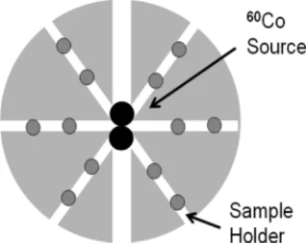
Fig. 1. Schematic diagram of the supporting disk for gamma-ray-irradiation. The Co source doses are 1000 Ci (upper) and 29 000 Ci (lower).
dosages of gamma-ray-irradiation were measured for the first time. Furthermore, the tolerable irradiation dosage of LiNbO waveguides were also studied and compared.
II. EXPERIMENT ANDRESULTS
Several x-cut y-propagation LiNbO substrates of sizes 1.1 cm 2.1 cm were chosen for the experiment. Acetone and ether solutions were used to clean LiNbO substrates in order to maintain a high quality of transmission. Some of the PE channel waveguides were annealed at 350 C for 0.5 h to become APE channel waveguides. The width of the waveguide defined by gold patterns was 4 m. After the preparation of the LiNbO waveguides, samples were irradiated by gamma-ray with a dosage rate of 800 krad/h. The gamma rays are radiated from two Co sources. The doses are 29 000 and 1000 Ci, and each source contains gamma rays of energies 1.33 and 1.17 MeV. The one with a smaller dose is for fine tuning, so an accurate desired dose can be obtained. A schematic diagram of the gamma-ray-irradiation setup on the supporting disk is shown in Fig. 1. The optical power and transmission loss mea-surement setup were shown in Fig. 2. A He–Ne laser beam of wavelength of 633 nm is passed through the polarizer; the laser beam is then coupled into the waveguide via a 40 objective lens. Another 40 objective lens receives the total beam from the waveguide and is analyzed by the laser beam analyzer and the optical power meter. The transmission loss was measured by the cut-back method. The measured transmission losses of waveguides made by five different kinds of methods are listed as Table I.
After gamma-irradiation, the transmission loss of a metal-diffusion LiNbO waveguide becomes larger with the increasing of gamma dosages. Fig. 3 shows the optical power intensity contours of four Ti LiNbO waveguides irradiated at dosages of 0, 3, 8, and 14 Mrad, respectively.
LAI et al.: STUDY OF GAMMA-IRRADIATION DAMAGE IN LiNbO WAVEGUIDES 1003
Fig. 2. Measurement setup for the waveguide.
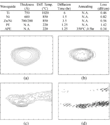
TABLE I
DIFFERENTLiNbO WAVEGUIDESTRUCTURES
Fig. 3. Output field contours versus dosage (Mrad) (a) 0, (b) 3, (c) 8, (d) 14.
For the same width of 4 m, the height of optical field of the 3-Mrad irradiated Ti LiNbO waveguide is smaller than that of nonirradiated sample by half of magnitude. As high energy bombardment of the gamma-irradiation causes damage to the LiNbO sample, the ability of optical confinement in the waveguide becomes worse with the increasing dosages. After a gamma-irradiation dosage of 14 Mrad, the laser beam can no longer be supported in the LiNbO waveguide. With the increasing gamma-ray dosage, the structural damage of the LiNbO waveguide will be increased, and the difference between the waveguide and substrate will also be decreased, which is the most important reason for the decreasing of guiding performance. Power loss of five different LiNbO waveguides as a function of the gamma-irradiation dosage are shown in Fig. 4. The increase of transmission-loss of the Ni-diffusion LiNbO waveguide is larger than those of the other metal-diffusion LiNbO waveguides, which indicates that
Fig. 4. Power loss of LiNbO waveguide as a function of dosage.
Fig. 5. Power losses of ridge and planar APE channel-waveguide as a function of gamma-irradiation dosage.
the Ni-diffusion LiNbO waveguide has a weaker antiradiation ability. In the harsh gamma-ray-irradiation environment, the increase of the transmission loss is about 1 dB/cm per dosage of 2.5 Mrad. However, most of the metal-diffusion waveguides have an increasing transmission loss of 1 dB/cm per 3.5 Mrad. The rate of change of the APE planar channel-waveguide is about 0.12 dB/cm every Mrad, which is much smaller than those of the PE and metal-diffusion planar channel-waveguides. After postannealing, the APE planar channel-waveguide has a stronger physical structure and has a better anti-irradiation ability. Under the same dosage of 10 Mrad, the power loss of the PE planar channel-waveguide is larger than that of an APE planar channel-waveguide by a magnitude of four times. Better anti-irradiation ability of the APE planar channel-waveguide is attributed to the better and stronger structure. The ridge APE channel and planar waveguide irradiated with the same dosage of gamma-irradiation has a lower power loss than planar APE waveguide, as shown in Fig. 5. The power losses of ridge and planar channel-waveguides per Mrad are 0.06 and 0.12 dB/cm, respectively. Obviously, the ridge channel-waveguide shows the best anti-irradiation ability in a harsh gamma-ray environ-ment. To know the gamma-irradiation damage in optical-fiber communication systems, the power losses of Ti LiNbO waveguides operating at wavelengths 1300 and 1550 nm are also measured, as shown in Fig. 6. As can be seen from the
1004 IEEE PHOTONICS TECHNOLOGY LETTERS, VOL. 19, NO. 13, JULY 1, 2007
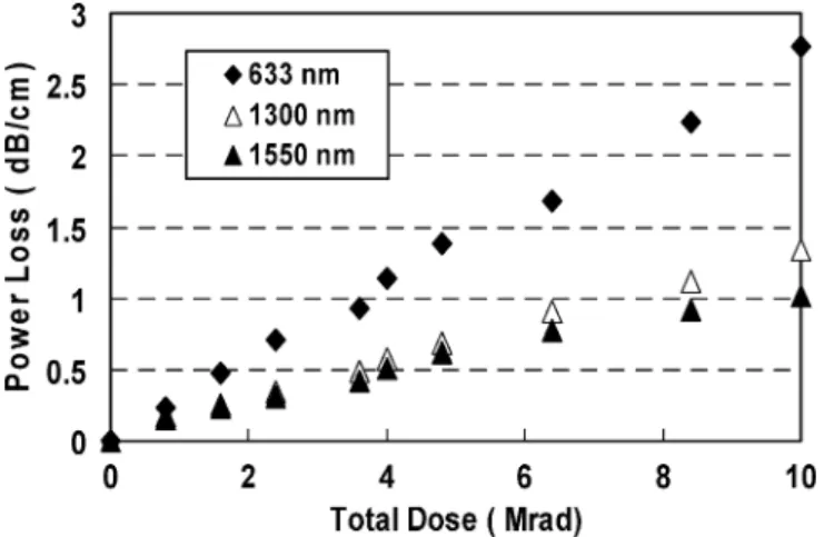
Fig. 6. Power losses of three wavelengths in Ti : LiNbO waveguides as a function of gamma-irradiation dosage.
figure, the power losses are increased with the increasing dosages, which are quite similar to those found at 633-nm wavelength.
III. CONCLUSION
Optical transmission characteristics of gamma-irradiated LiNbO waveguides made by Ti-diffusion, Ni-diffusion, Zn–Ni-diffusion, PE, and APE have been successfully mea-sured. With the increasing gamma-irradiation intensity, the APE waveguide is the most anti-irradiative and has the lowest transmission loss, where the measurements were carried out at the wavelength of 633 nm, while all samples were irradiated with a total amount of 10 Mrad and a dosage of 800 krad/h.
The power losses of ridge and planar channel-waveguides per Mrad are 0.06 and 0.12 dB/cm, respectively. And the ridge channel-waveguide exhibits the best anti-irradiation ability in a harsh gamma-ray environment. For the reference of optical communication, the characteristics of Ti LiNbO waveguides at 1300- and 1550-nm wavelengths are measured. The results demonstrated in this work would be helpful for further research and applications of LiNbO waveguide devices in harsh radi-ation environments.
REFERENCES
[1] A. Holmes-Siedle, “Radiation effects in space, nuclear power and ac-celerators: Impact on optics and light sensor,” SPIE Critical Rev. Sci. and Technol. Advancement Photon. for Space, vol. CR66, pp. 37–57, 1997.
[2] E. W. Taylor, “Radiation effects in LiNbO ,” in Properties in Lithium Niobate, ser. IEE EMIS DATAREVIEWS 28, K. K. Wong, Ed.. U.K.: INSPEC, 2002, pp. 359–371.
[3] Y. Ohmori, M. Yamaguchi, K. Yoshino, and Y. Inuishi, “Optical damage in LiNbO induced by X-ray irradiation,” Jpn. J. Appl. Phys., vol. 16, no. 1, pp. 181–182, 1977.
[4] E. Colby, G. Lum, T. Plettner, and J. Spencer, “Gamma radiation studies on optical materials,” IEEE Trans. Nucl. Sci., vol. 49, no. 6, pt. 1, pp. 2857–2867, Dec. 2002.
[5] K. P. Lor, Q. Liu, and K. S. Chaing, “UV-written long-period gratings on polymer waveguides,” IEEE Photon. Technol. Lett., vol. 17, no. 3, pp. 594–596, Mar. 2005.
[6] F. Berghmans, F. Vos, and M. Decreton, “Evaluation of three different optical fiber temperature sensor types for application in gamma radi-ation environment,” IEEE Trans. Nucl. Sci., vol. 45, no. 3, pt. 3, pp. 1537–1542, Jun. 1998.
[7] W. H. Hsu, K. C. Lin, J. Y. Li, Y. S. Wu, and W. S. Wang, “Polar-ization splitter with variable TE-TM mode converter using Zn and Ni codiffused LiNbO waveguides,” IEEE J. Sel. Topics Quantum Elec-tron., vol. 11, no. 1, pp. 271–277, Jan./Feb. 2005.
[8] R. S. Cheng, T. J. Wang, and W. S. Wang, “Wet-etched ridge waveg-uides in Y-cut lithium niobate,” J. Lightw. Technol., vol. 15, no. 10, pp. 1880–1887, Oct. 1997.