HIGH-RESOLUTION FIBER BRAGG
GRATING SENSOR SYSTEM USING
LINEAR-CAVITY FIBER LASER SCHEME
Peng-Chun Peng, Hong-Yih Tseng, and Sien ChiInstitute of Electro-Optical Engineering National Chiao-Tung University Hsinchu, Taiwan, 300, R.O.C. Received 15 February 2002
ABSTRACT: A high-resolution fiber Bragg grating (FBG) sensor sys-tem using a linear-cavity fiber laser scheme is proposed and numerically studied. The proposed sensor system can improve the sensing accuracy by using a discriminating FBG pair in conjunction with a fiber laser scheme. This FBG sensor system can resolve the temperature up to 0.0005°C theoretically and can be applied for strain sensing and tem-perature sensing with high precision. © 2002 Wiley Periodicals, Inc. Microwave Opt Technol Lett 34: 323–325, 2002; Published online in Wiley InterScience (www.interscience.wiley.com). DOI 10.1002/mop. 10450
Key words: fiber sensor; fiber Bragg grating; linear-cavity fiber laser 1. INTRODUCTION
Fiber Bragg gratings (FBGs) have been widely discussed in the areas of lightwave communication systems and sensor systems [1, 2]. The FBG sensors have attracted considerable attention in recent years because of their ease in handling, low cost, small size, and inherent advantages incorporated with fiber communication sys-tems [2– 6]. By detecting the Bragg wavelength shift, the FBG sensors can measure many physical quantities, such as strain, temperature, and pressure. Several configurations of the FBG sensors launch broadband sources into the FBGs to reflect light with sensing information from the Bragg wavelength shift [3– 6]. The conventional grating spectrometer and the scanning fiber Fabry–Perot filter can interrogate the Bragg wavelength shift. However, such interrogating configurations are expensive and have a low signal-to-noise ratio (SNR). Moreover, increasing the precision is difficult for these wavelength interrogation schemes.
This Letter proposes a novel high-resolution FBG sensor based on a linear-cavity fiber laser scheme. An FBG acting as a mirror of the linear-cavity fiber laser is the sensing element. To monitor the Bragg wavelength shift from the sensing FBG, another two FBGs with different Bragg wavelengths reflect the output of the linear-cavity fiber laser to discriminate the lasing wavelength from the back-reflected power. The proposed sensor system can improve the sensing accuracy by using this discriminating FBG pair in con-junction with a fiber laser scheme. Such a sensor system can increase the sensing resolution, enhance the SNR, and reduce the errors induced by scanning the whole spectrum of the sensing element.
2. DESIGN METHOD OF LINEAR-CAVITY FIBER LASER SENSOR
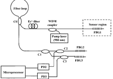
Figure 1 schematically shows the proposed FBG sensor system using a linear-cavity fiber laser scheme. The linear-cavity fiber laser is comprised of a sensing fiber grating (FBG1), a fiber loop mirror, and a section of erbium-doped fiber pumped by a 980-nm laser diode. The lasing light emerging from coupler C0 travels through a 1⫻ 2 coupler (C1) and splits into two 2 ⫻ 1 couplers (C2 and C3) with equal optical power. The output light from each
2⫻ 1 coupler is launched into a fiber grating (FBGj, j ⫽ 2 or 3). The back-reflected light from each FBGj then propagates through the corresponding 2⫻ 1 coupler to the detector (PDj). The output intensity from each PDj finally is fed into a microprocessor to accurately calculate the lasing wavelength by discriminating the reflected power from FBGj. The present Letter attempts to design such a sensor system for sensing the temperature with high preci-sion.
To design the above-mentioned FBG sensor system, the fiber loop mirror is first discussed. Such a fiber loop mirror is a type of all-fiber reflector [7]. The reflection (R) and transmission (T) of this fiber loop mirror can be expressed as [7]
R⫽ 4K共1 ⫺ K兲, (1)
T⫽ 共1 ⫺ 2K兲2, (2)
where K is the coupling coefficient of the fiber coupler C0. Equations (1) and (2) are obtained under the assumption that the fiber length of the loop is sufficiently small to avoid the nonlinear fiber loop effect [8].
Another mirror for the linear-cavity fiber laser is FBG1. As-suming all the FBGs in the proposed configuration are uniform grating with sinusoidal index perturbation, the reflectivity of each FBG can be analytically derived according to the coupled mode equations [9]. When the temperature changes with amount⌬T, the Bragg wavelength of FBG1 shifts toT[10]
T⫽ 关1 ⫹ 共␣ ⫹ 兲 ⌬T兴B, (3)
where␣ is the thermal expansion coefficient, is the thermo-optic coefficient, andBis the original Bragg wavelength of FBG1. This
original Bragg wavelength is given by
B⫽ 2n⌳, (4)
where⌳ is the grating period and n is the fiber refractive index. Now the erbium-doped fiber (EDF) of the linear-cavity laser is investigated. The erbium atoms are modeled as a homogeneously broadening two-level system. The amplified spontaneous emission (ASE) spectrum for such a two-level system is divided into N slots with each frequency bandwidth⌬icentered at the wavelengthi. Contract grant sponsor: Academic Excellence Project of Ministry of
Edu-cation, Taiwan, R.O.C.; contract grant number: 90-E-FA06-1-4-90X023.
Figure 1 Proposed configuration of the high-resolution fiber Bragg grating sensor system based on a linear-cavity fiber laser scheme
The initial conditions for the forward ASE PASE⫹ atiand for the
backward pumping power Pp⫺atP⫽ 980 nm are
Pp⫺共P兲 ⫽ PP0 at z⫽ L and PASE⫹ 共i兲 ⫽ 0 at z ⫽ 0, (5)
where PP
0 is the input pumping power, and L is the EDF length. In
addition, the input signal is zero; and the lasing signals denoted by
Ps⫾propagate in both directions and superpose with each other.
Above the threshold conditions, the generation and amplification of the forward ASE PASE⫾ and the backward ASE PASE⫺ within the EDF are sufficient to give rise to the lasing condition. By using the Runge–Kutta algorithm, the steady-state relations between Pp⫺,
Ps⫾, and PASE⫾ can be described by the homogeneously broadening
rate equations under the boundary conditions [11]:
关PS⫹共i兲兴n⫽ 关PASE⫺ 共i兲 ⫹ P⫺S共i兲兴n⫺1RFL共i兲MFL at z⫽ 0, (6)
关PS⫺共i兲兴n⫽ 关PASE⫹ 共i兲 ⫹ P⫹S共i兲兴n⫺1R1共i兲M1 at z⫽ L, (7)
where the subscript n is the nth iteration during algorithm, MFLis the loss due to the fiber loop mirror, M1is the loss due to the FBG1
reflector, R1(i) is the reflectivity of FBG1, and RFL(i) is the
reflectivity of the fiber loop mirror. IfFLand1are defined as the
intracavity losses for either side of the linear cavity, the output laser power is given by
PLas⫽ 共1 ⫺ RFL兲FLPRout, (8)
where PR
outis the power at the lasing wavelength emerging from
the end of the gain fiber.
The splicing losses and the coupling losses due to the couplers are neglected. The lasing light now is launched into FBG2 and FBG3 with equal power. With different Bragg wavelengths2and 3, respectively, FBG2 and FBG3 reflect different power from the
lasing light. Subsequently, the reflected power PRj from each
FBGj can be expressed as
PR2⫽
冏
i2sin共q2Lg兲
q2cos共q2Lg兲 ⫺ i␦2sin共q2Lg兲
冏
2
PLas, (9)
PR3⫽
冏
i3sin共q3Lg兲
q3cos共q3Lg兲 ⫺ i␦3sin共q3Lg兲
冏
2
PLas, (10)
wherejis the coupling coefficient of each FBGj, qjis defined by
qj⫽ 公␦j2⫺j2, and␦j⫽ 2n(T⫺1⫺j⫺1) implies the lasing
detuning from the exact Bragg resonance of FBGj. Here, FBG2 and FBG3 are assumed to have identical grating length Lg. The
lasing wavelength is defined by Eq. (3) and it is dependent on the temperature drift⌬T. Consequently, by identifying the reflected power PR2 and PR3, the microprocessor can discriminate the lasing wavelength and further estimate the temperature drift⌬T accurately.
3. NUMERICAL EXAMPLE
In this Letter a linear-cavity fiber laser is designed with FBG1 Bragg wavelengthB ⫽ 1550 nm, the thermal expansion
coeffi-cient␣ ⫽ 1.1 ⫻ 10⫺6/°C, and the thermo-optic coefficient ⫽ 8.6⫻ 10⫺6/°C. According to Eq. (3), the lasing wavelength T
will shift to 1550.1 nm when the temperature drift⌬T is 6.65 °C. Moreover, it is assumed that the FBG1 maximum reflectivity is 100%, the reflectivity of the fiber loop mirror is 84% (K⫽ 0.3), and the 980-nm pumping power is 52 mW. Under these assump-tions, Figure 2 shows the numerical results of the output spectrum of the linear-cavity fiber laser. The output power of this fiber laser is 10 mW.
Figure 3 shows the reflectivity of FBG2 (solid line) and FBG3 (dotted line). The Bragg wavelengths of FBG2 and FBG3 are assumed to be2⫽ 1550.05 nm and3⫽ 1550.35 nm. At ⌬T ⫽ 0 °C, the original lasing wavelengthB⫽ 1550 nm corresponds
to the FBG2 reflectance 93.42% and the FBG3 reflectance 27.47%. Hence the detected back-reflected power is 4.624 mW from PD2 and 1.360 mW from PD3. When the temperature changes with ⌬T ⫽ 6.65 °C, the lasing wavelengthT ⫽ 1550.1 nm
corre-sponds to the FBG2 reflectance 93.68% and the FBG3 reflectance 72.53%. Thus the temperature drift results in 4.637 mW from PD2
Figure 2 Output spectrum of linear-cavity fiber laser
Figure 3 Reflectivity of FBG2 (solid line) and FBG3 (dotted line)
and 3.590 mW from PD3. Similar to the above-mentioned exam-ple, the microprocessor can establish a look-up table for PR2, PR3,
and ⌬T in the data base. In order to sense the temperature drift with high precision, a power meter like ILX Lightwave OMM-6810B can be used to establish the look-up table. Such a power meter can resolve the optical power to 10⫺5mW. Furthermore, because FBG2 and FBG3 have to discriminate the lasing wave-length, they should be arranged in a temperature controller for stable measurement. Consequently, by using such a discriminating FBG pair incorporated with a linear-cavity fiber laser, the tem-perature drift can be accurately estimated with resolution up to 0.0005°C, according to Eqs. (3), (9), and (10).
4. CONCLUSION
In summary, a high-resolution FBG sensor has been designed using a linear-cavity fiber laser scheme. The fiber laser in conjunc-tion with a discriminating FBG pair can increase the sensing resolution. The theoretical model is established and a numerical example is shown. Such an FBG sensor system can be applied for strain sensing and temperature sensing with high precision.
REFERENCES
1. K.O. Hills and G. Meltz, Fiber Bragg grating technology fundamentals and overview, J Lightwave Technol 15 (1997), 1263–1276. 2. C.C. Chen, J.M. Gong, W. Jin, and M.S. Demokan, Investigation of
unwanted interferometric signals in a fiber Bragg grating sensor using a tunable laser and a first derivative interrogation technique, Opt Commun 173 (2000), 203–210.
3. A.D. Kersey, M.A. Davis, H.J. Partrick, M. Leblance, K.P. Koo, C.G. Askins, M.A. Putnam, and E.J. Friebele, Fiber grating sensors, J Lightwave Technol 15 (1997), 1442–1463.
4. G.A. Johnson, M.D. Todd, B.L. Althouse, and C.C. Chang, Fiber Bragg grating interrogation and multiplexing with a 3⫻ 3 coupler and scanning filter, J Lightwave Technol 18 (2000), 1101–1105. 5. K.C. Chen, W. Jin, J.M. Gong, and M.S. Demokan, FMCW
multi-plexing of fiber Bragg grating sensors, IEEE J Selected Topics Quan-tum Electron 6 (2000), 756 –763.
6. L. Zhang, Y. Liu, J.A.R. Wiliams, and I. Bennion, Enhanced FBG strain sensing multiplexing capacity using combination of intensity and wavelength dual-coding technique, IEEE Photon Technol Lett PTL-11 (1999), 1638 –1641.
7. F. Sanchez, Matrix algebra for all-fiber optical resonators, J Lightwave Technol 9 (1991), 838 – 844.
8. N.J. Doran and D. Wood, Nonlinear-optical loop mirror, Opt Lett 13 (1988), 56 – 60.
9. G.P. Agrawal, Applications of nonlinear fiber optics, Academic, New York, 2001.
10. M.G. Xu, L. Reekie, Y.T. Chow, and J.P. Dakin, Optical in-fiber grating high pressure sensor, Electron Lett 29 (1993), 398 –399. 11. A. Cucinotta, L. Seleri, L. Vincetti, and M. Zoboi, Numerical and
experimental analysis of erbium-doped fiber linear cavity lasers, Opt Commun 156 (1998), 264 –270.
© 2002 Wiley Periodicals, Inc.
EXPERIMENTAL STUDY OF A
BROADBAND U-SLOT TRIANGULAR
PATCH ANTENNA
Yong-Woong Jang
Department of Electronic Communication Engineering Keukdong College
38 Danpyung-Ree
Kamgok-Myun, Eumsung-Kun Chungbuk, 369-850, Korea Received 8 February 2002
ABSTRACT: This Letter describes a U-shaped aperture-coupled U-slot triangular patch antenna fed by microstrip feed line. Because a thick aperture substrate with a dual U-slot patch radiator are used in the de-sign, a high level of coupling to the feed line results. The measured bandwidth of approximately 84.9% (VSWRⱕ 2.0) and a gain of 6.5 dBi have been obtained. The experimental far-field patterns are stable across the passband. © 2002 Wiley Periodicals, Inc. Microwave Opt Technol Lett 34: 325–327, 2002; Published online in Wiley InterScience (www.interscience.wiley.com). DOI 10.1002/mop.10451
Key words: microstrip; antennas; broadband antennas 1. INTRODUCTION
Microstrip patches antennas have become the favorite choice of antenna designers because they offer the attractive features of low profile, low cost, conformability, and ease of manufacture. Patch antennas are receiving increasing interest in various mobile com-munication systems, because they can provide advantages over traditional whip and helix antennas in term of high efficiency, low EM coupling to human head, and increased mechanical reliability [1]. However, the primary barrier to implementing these antennas in many applications is their limited bandwidth— only on the order of a few percent for a typical patch radiator. Because of this fact, much work has been devoted to increasing the bandwidth of microstrip antenna, and a technique that has been used is a near-resonance aperture. In this manner, bandwidth on the order of 20% can be achieved [2]. Another technique that has been used exten-sively is the aperture-coupled stacked patch antenna (bandwidth is 30 –50%) [3, 4]. A broadband air-filled stacked U-slot patch an-tenna has also been studied. Bandwidth on the order of 44% can be achieved [5]. The slot-coupled microstrip antenna with a triplate line feed has been achieved [6]. Recently, a T-shaped microstrip-fed single-layer single-slot antenna [7] with an impedance band-width of 45% has been also presented. And a shorted triangular patch fed L-probe was shown to obtain 61% bandwidth [8].
In this Letter, an alternative design technique that combines a U-shaped aperture-coupled U-slot triangular patch antenna fed by the microstrip feed-line concept is proposed. It is demostrated that through the combination of these conventional techniques, the bandwidth and the cross-polarization level can be improved sub-stantially just like in conventional microstrip patches. The pro-posed aperture-coupled antenna has simillar radiation patterns but larger impedance bandwidth (84.9%) than microstrip designs uti-lizing coupled stacked patches [3–5] and other aperture-coupled patch antennas [2, 6], which seldom exceeds 50% for the microstrip-fed case. Experimental results for the broadband per-formance and the radiation pattern are also presented.
2. ANTENNA STRUCTURE AND EXPERMENTAL RESULTS
The geometry and design parameters of a U-shaped aperture-coupled U-slot triangular patch antenna fed by microstrip feed line are shown in Figure 1, along with the dimensions of the wide-band