Experimental modeling and design optimization of push-pull
electret loudspeakers
Mingsian R. Baia兲 and Chun-Jen Wang
Department of Mechanical Engineering, National Chiao-Tung University, 1001 Ta-Hsueh Road, Hsin-Chu 300, Taiwan
Dar-Ming Chiang and Shu-Ru Lin
Taiwan Electrets Electronics Co., Ltd., 7F-3, 9, Prosperity 1st Road, Hsinchu Science Park, Hsinchu City 30078, Taiwan
共Received 9 August 2009; revised 4 December 2009; accepted 3 February 2010兲
A fully experimental modeling technique and a design optimization procedure are presented in this paper for push-pull electret loudspeakers. Conventional electrical impedance-based parameter identification methods are not completely applicable to electret speakers due to the extremely weak electromechanical coupling. This prompts the development of an experimental technique for identifying the electroacoustic parameters of the electret speakers. Mechanical parameters are identified from the membrane velocity measured using a laser vibrometer. The voltage-force conversion factor and the motional impedance are estimated, with the aid of a test-box method. This experimentally identified model serves as the simulation platform for predicting the response of the electret loudspeaker and optimizing the design. Optimal parameters are calculated by using the simulated annealing 共SA兲 algorithm to fulfill various design goals and constraints. Either the comprehensive search for various parameters or the simple search for the optimal gap distance can be conducted by this SA procedure. The results reveal that the optimized design has effectively enhanced the performance of the electret loudspeaker.
© 2010 Acoustical Society of America. 关DOI: 10.1121/1.3337224兴
PACS number共s兲: 43.38.Bs, 43.38.Ja, 43.40.Dx 关AJZ兴 Pages: 2274–2281
I. INTRODUCTION
Electret loudspeakers are the electrostatic loudspeakers with precharged membranes. Electret loudspeakers offer ad-vantages of compactness, light weight, excellent mid- and high frequency reproductions, high electroacoustic effi-ciency, waiver of externally bias circuit, etc.1 Due to these characteristics, the loudspeakers have promise in the appli-cation to consumer electronics.
Electret configuration will result in slightly different forms of voltage-force sensitivity and the associated nonlin-earity from those of conventional push-pull electrostatic loudspeakers. Nevertheless, one may equate the electret elec-trostatic speaker with an external polarizing voltage. On the surface, the two kinds of loudspeaker look alike. Their equivalent electrical circuits are the same and the analyses of their mechanical and acoustical parameters are identical. However, where they differ is in the electromechanical force conversion. A non-electret electrostatic has an external polar-izing voltage supply, which creates a monopole charge on the membrane. For an electret speaker this is difficult to achieve because, in the absence of a supply, a monopole charge is relatively unstable over time. Hence, electret speakers typi-cally use membranes with conductive coatings, which carry an induced charge of opposite polarity共dipoles兲 to that of the membrane. This makes the analysis somewhat more
compli-cated. It turns out that the two kinds of loudspeaker are equivalent but not the same. In the case of the dipole electret, it is like applying a polarizing voltage of an equivalent non-electret speaker across the conductive coating and a virtual electrode somewhere in the middle of the membrane, where this virtual electrode contains all the membrane charge in a concentrated layer. The electrical input capacitance of an electret speaker is also different from that of a non-electret type due to the presence of the electret membrane, although the contribution this makes depends on the size of the air gap.2,3
Electret materials have been studied by several research-ers. Lekkala and Paajanen4 introduced a new electret mate-rial, electromechanical film 共EMFi兲, at the turn of the cen-tury. Not before long, EMFi was applied to microphones, actuators, and even loudspeaker panels.5 Cao et al.6 dis-cussed the relationship between the microstructures and the properties of the electret material, where the electret proper-ties of the porous polytetrafluoroethylene共PTFE兲 were stud-ied. It is found that the porous dielectrics can be good elec-tret materials. Recently, Chiang et al.7 proposed the nanoporous Teflon-fluorinated ethylene propylene film that allows for higher charge density stored in the film with im-proved stability. The nanoporous electret material was ap-plied to flexible electrostatic loudspeakers.8 Their electret diaphragms are made of fluoro-polymer with nano-meso-micro-pores precharged by the corona method.
It was not until recently that Mellow and Kärkkäinen3,9 conducted a rigorous theoretical analysis of electret
loud-a兲Author to whom correspondence should be addressed. Electronic mail:
speakers. Transducers with single-ended and push-pull con-structions are investigated in terms of the static force acting on the diaphragm and the stored charge density. Bai et al.10 suggested a hybrid modeling approach combining experi-mental measurement and finite-element-analysis共FEA兲 for a single-ended electret loudspeaker. Experimental verification reported in the work revealed that the single-ended loud-speaker suffered from high nonlinear distortion problems.
This paper aims at three purposes. First, electret loud-speakers in push-pull construction are proposed in order to reduce the nonlinear distortions encountered in the single-ended device. Second, a more accurate fully experimental modeling technique is suggested to estimate the lumped pa-rameters of the equivalent circuits without resorting to FEA. Because the coupling between the electrical and mechanical systems is extremely weak, the parameters of the mechanical system are unidentifiable using the electrical impedance measurement.11–13To overcome the difficulty, a test-box ap-proach in conjunction with laser measurement is taken in this paper. Third, on the basis of the preceding simulation model, an optimization procedure using simulated annealing 共SA兲 algorithm14–16is developed, aiming at optimizing design pa-rameters of electret loudspeakers to maximize the sound pressure level共SPL兲 output and the bandwidth as well.
II. EXPERIMENTAL MODELING OF ELECTRET LOUDSPEAKERS
A. Operating principles
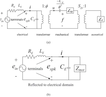
A sample of a 493⫻129 mm2 electret loudspeaker is shown in Fig. 1共a兲. In its push-pull construction, the loud-speaker comprises a charged flexible membrane and two per-forated rigid back plates with 52.1% perforation ratio. The membrane is made of fluoro-polymer, which contains nano-pores to enhance the charge stability and density.8The mem-brane is placed at the center between two electrode plates spaced by 2.4 mm, as shown in Fig.1共b兲. The construction is also referred to as the push-pull configuration with a fully floating membrane by Mellow and Kärkkäinen.3The mem-brane is divided into six equal partitions共242⫻37 mm2兲 by stainless steel spacers.
Due to high input impedance of the electret loudspeaker, a transformer is used for impedance matching and espkis the output voltage of the transformer. The turn ratio is 138. The net force f acting on the membrane can be estimated by3
f = rr1hSDm 2共rd +r1h兲2 espk+ rr1h 2S Dm 2 20共rd +r1h兲3␦ =espk+␦, 共1兲 whererandr1are the relative permittivities of the
mem-brane and the medium at the gap, respectively, 0 is the vacuum permittivity, h is one-half of the thickness of the membrane, SD is the area of membrane, m is the surface
charge density of the membrane, d is the gap between the membrane and the electrode plate, and␦is the displacement of the membrane. The first term of Eq.共1兲is due to the input voltage, whereas the second term is due to the negative stiff-ness resulting from the membrane attractions. The
voltage-force conversion factorand the negative stiffnesscan be written as3 = K1 d2, dⰇ r1h r 共2兲 with K1=r1hSDm/2r, and =K2 d3, dⰇ r1h r 共3兲 with K2=r1h2SDm 2/2 0r 2 . B. Analogous circuits
The electret loudspeaker can be modeled with the analo-gous circuit, as shown in Fig.2共a兲. The mechanical imped-ance and the radiation impedimped-ance are identified as a lumped sum in the parameter identification procedure. That is, the radiation impedance has been taken into account in the mod-eling. In the electrical domain, the circuit is modeled with the Thévenin equivalent circuit, where ein is the voltage source of the transformer input, i is the current, and RE and
LE are the electric resistance and inductance of the
trans-former. CE is the static capacitance when the membrane is
blocked. In the mechanical domain, ZMrepresents the
open-circuit mechanical impedance and u is the membrane veloc-ity. In the acoustical domain, ZA represents the acoustical
impedance.
(a)
spk
e
(b)
FIG. 1.共Color online兲 The push-pull electret loudspeaker. 共a兲 Photo. 共b兲 The schematic of the loudspeaker construction.
Figure2共b兲 shows the combined circuit as the mechani-cal and acoustimechani-cal systems are reflected to the electrimechani-cal sys-tem, where the motional impedance Zmotis defined as
Zmot= Zms+ SD 2 ZA 2 , 共4兲 Zms= ZM−
冉
j CE 2冊
−1 , 共5兲where Zmsis the short-circuit mechanical impedance andis
the angular frequency. To measure the electrical impedance, we need an experimental arrangement, as shown in Fig.3共a兲. The input voltage from the signal generator eg is 1.5 V and
the current-sampling resistor R is 100 ⍀. The electrical im-pedance of the loudspeaker is given by
Zspk=egG1G2− eR eR
R, 共6兲
where G1and G2denote the effective gains of the amplifier and the transformer, respectively, and eRis the voltage drop
across the resistor R. The thus measured electrical impedance of Fig. 3共b兲 resembles that of a capacitance due to weak electromechanical coupling10
兩ZE兩 = 共CE兲−1. 共7兲
It follows that only the static capacitance CEcan be extracted
from the electrical impedance measurement
CE=共兩ZE兩兲−1. 共8兲
For the sample in Fig.1, the CEwas found to be 1.86 nF.
C. Parameter identification
In Fig. 2共b兲, as the inductance LE of the transformer
output end is connected to the electret loudspeaker, which behaves like a capacitance due to the aforementioned weak
coupling, the combined electrical system becomes a second-order low-pass system. Figure 4 shows the frequency re-sponse of the unloaded transformer, which is nearly constant throughout the range 20–20 kHz. As the electret loudspeaker is connected to the transformer, the frequency response be-comes a low-pass function with cutoff frequency E0
= 8736.4 Hz as follows: 1: u 2 SD:1 E C E R LE spk
e
CE ine
(a)Z
mot+
-E
R
L
E+
-spk
e
ine
terminalsC
EReflected to electrical domain (b)
FIG. 2. The electroacoustic analogous circuits of the push-pull electret loud-speaker.共a兲 Electrical, mechanical, and acoustics systems. 共b兲 Combined circuit referred to the electrical system.
Amplifier Transformer Signal generator Analyzer Resistor Ch. 2 Ch. 1 R eg eR Push-pull electret loudspeaker (a) (b)
FIG. 3. 共Color online兲 The electrical impedance measurement of the push-pull electret loudspeaker.共a兲 Experimental arrangement. 共b兲 The electrical impedance versus the motional impedance.
101 102 103 104 105
101 102 103
Output Voltage of Transformer
Frequency (Hz) Vo lt a g e (v ) Loaded, measured Loaded, simulated Unloaded, measured
FIG. 4. 共Color online兲 The comparison of the measured and simulated out-put voltage responses of the loaded and unloaded transformers.
espk共s兲 = H共s兲ein共s兲 = 1 CELEs2+ CEREs + 1 ein共s兲 = 1
冉
s E0冊
2 + 1 QE s E0 + 1 ein共s兲, 共9兲where H共s兲 is the transfer function between espkand ein, QE
is the quality factor, and s = j is the Laplace variable. The effective inductance and resistance at the output end of the transformer can be calculated by
LE=共E0
2
CE兲−1, 共10兲
RE=共QEE0CE兲−1. 共11兲
At the resonance frequency, the real part of the transfer func-tion in Eq.共9兲is zero. It follows that the quality factor can be calculated by
兩H共jE0兲兩 = 兩− jQE兩 = QE. 共12兲
For the sample in Fig.1, the quality factor QE= 0.6845, the
inductance LE= 0.178 H, and the resistance RE= 14.3 k⍀,
respectively. In Fig.4, the measurement共solid line兲 and the simulation 共dashed-dotted line兲 of espk are in good agree-ment. The cutoff frequency is measured according to the phase switching principle.
As mentioned previously, the mechanical parameters are unidentifiable with the electrical impedance measurement. We need to devise a method based on direct mechanical mea-surement. To this end, the electrical and acoustical systems are reflected to the mechanical system, as shown in Fig.5共a兲. For simplicity, we approximate the combined acoustical im-pedance and the mechanical imim-pedance to be a second-order system. The lumped parameters RM, MM, and CM
⬘
denote theresistance, the mass, and the compliance, respectively, of the combined impedance.
Due to weak coupling 共⬇0兲, RE2 and LE2 can be
neglected, leading to the simplified circuit of Fig.5共b兲. Solv-ing the circuit yields the expression of the membrane veloc-ity u as follows: u = CMs MMCMs2+ RMCMs + 1 ein = 1 RM 1 Qu
冉
s 0冊
冉
s 0冊
2 + 1 Qu冉
s 0冊
+ 1 ein, 共13兲where the compliance CM is the series combination of CM
⬘
and the negative compliance −CE/2,0is the fundamental resonance frequency, and Quis the quality factor. The
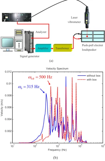
mem-brane velocity can be measured by a laser vibrometer, as shown in Fig.6共a兲. In the following, we concentrate on only the fundamental mode and ignore higher-order modes. From the velocity measurement, the fundamental resonance fre-quency0can be located and the quality factor correspond-ing to the fundamental resonance can be estimated as fol-lows:
u
in e
2 E C C
M M M RM 2 E R LE
2 2 E C (a)u
ine
2 E C C
M M M RM (b)FIG. 5. The electroacoustic analogous circuits of the push-pull electret loud-speaker.共a兲 Combined circuit referred to the mechanical system. 共b兲 The weakly coupled approximation.
0.012 101 102 103 104 105 0 0.002 0.004 0.006 0.008 0.01 Velocity Spectrum Frequency (Hz) Ve lo ci ty (m /s ) without box 0B 500 Hz
with box 0 315 Hz
(b) Laser vibrometer (a) Amplifier Transformer Analyzer Push-pull electret loudspeaker Signal generatorFIG. 6. 共Color online兲 The membrane velocity measurement of the push-pull electret loudspeaker.共a兲 Experimental arrangement. 共b兲 The comparison of the velocity responses of the loudspeaker, with and without the test box.
Qu=
0 2−1
, 共14兲
where the 2 and 1 are ⫺3 dB points in the velocity re-sponse.
Given the0= 1/
冑
MMCM, it is impossible to determinethe respective values of the compliance CMand the mass MM
based on one measurement. To overcome the difficulty, a test-box method with volume 5.51 l is employed to obtain another velocity measurement. The result of the membrane velocity measurement is shown in Fig.6共b兲. The fundamen-tal resonance frequency is increased from 315 to 500 Hz due to the acoustical compliance of the test box. The additive acoustical compliance CABand the additive mechanical
com-pliance⌬CMdue to the test box can be calculated as
CAB= Vbox c2, 共15兲 ⌬CM= CAB SD2 , 共16兲
where Vboxis the volume of the test box, is the density of air, and c is the velocity of sound. Thus, based on these two membrane velocity measurements, the mechanical param-eters can be determined as
CM=
冋
冉
0B 0冊
2 − 1册
⌬CM, 共17兲 MM=共0 2 CM兲−1, 共18兲 RM=共0QuCM兲−1, 共19兲 CM⬘
= CM冉
CE 2冊
CM+ CE 2 , 共20兲where 0B is the fundamental resonance frequency of the velocity response when loaded with the test box and⌬CMis
the additive mechanical compliance due to the test box. Fi-nally, the voltage-force conversion factor can be deter-mined by letting=0in Eq.共13兲as follows:
=RMu共0兲 ein
, 共21兲
where u共0兲 is the peak magnitude of the membrane velocity response at the fundamental resonance frequency. Using the formula, is found to be 1.88⫻10−4 for the sample in Fig.1.
D. Numerical and experimental investigations
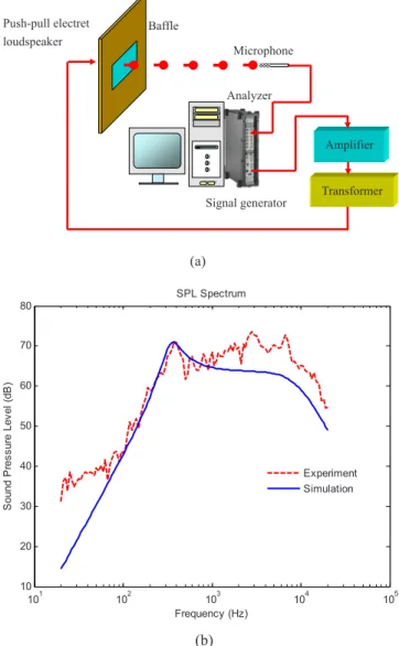
Experiments were conducted to validate the preceding model of the electret loudspeaker. The experimental arrange-ment for measuring the on-axis SPL is shown in Fig.7共a兲. According to the standard AES2-1984 共r2003兲,17 a 2475 ⫻2025 mm2 baffle is used in the measurement. The 132.6
Vrms swept-sine signal is used to drive the loudspeaker in the frequency range 20–20 kHz. The microphone is posi-tioned 1 m away from the loudspeaker.
Figure 7共b兲 compares the on-axis SPL responses ob-tained using the simulation and the measurement. The simu-lated response 共solid line兲 is in good agreement with the measured response 共dashed line兲, albeit discrepancies are seen at high frequencies due to un-modeled flexural modes of membrane. It should be borne in mind that, in the preced-ing model, only the fundamental mode is modeled in the analogous circuit and high-order modes are neglected.
It can also be observed from Fig. 7共b兲 that the SPL re-sponse starts to roll off at approximately 8 kHz due to the inductance of the transformer as predicted. Furthermore, in Fig.3共b兲, the motional impedance obtained using the model is much greater than the electrical impedance, rendering the former an open circuit in Fig.2共b兲. This is the evidence of weak coupling.
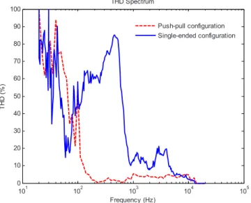
For assessing the nonlinear distortion of the electret loudspeaker, total harmonic distortion 共THD兲 is calculated from the measured on-axis SPL response.18 In Fig. 8, the
Push-pull electret loudspeaker Baffle (a) Signal generator Microphone Analyzer Amplifier Transformer 101 102 103 104 105 10 20 30 40 50 60 70 80 SPL Spectrum Frequency (Hz) S o u n d P re s su re L e ve l (dB ) Experiment Simulation (b)
FIG. 7.共Color online兲 The on-axis SPL measurement of the push-pull elec-tret loudspeaker.共a兲 Experimental arrangement. 共b兲 The comparison of the measured and the simulated on-axis SPL responses.
measured THD of the electret loudspeaker in push-pull con-struction is compared with that of the single-ended construc-tion, which was investigated by Bai et al.10 The average THD of the push-pull configuration is below 6% in the range 140–20 kHz, while the THD of the single-ended configura-tion can reach as high as 17%. Evidently, the push-pull con-figuration has effectively addressed the nonlinearity problem of the single-ended configuration.
III. PARAMETER OPTIMIZATION OF ELECTRET LOUDSPEAKERS
The preceding model of electret loudspeaker serves as a useful simulation platform for optimizing the loudspeaker parameters. In the following, a procedure based on the simu-lated annealing 共SA兲 algorithm14–16 is exploited for the de-sign optimization.
A. The SA algorithm
The SA algorithm is a generic probabilistic meta-algorithm for the global optimization problem, namely, locat-ing a good approximation to the global optimum of a given function in a large search space. The major advantage of the SA is the ability to avoid becoming trapped in the local minima. In the SA method, each state in the search space is analogous to the thermal state of the material annealing pro-cess. The objective function G is analogous to the energy of the system in that state. The purpose of the search is to bring the system from the initial state to a randomly generated state with the minimum objective function. An improve state is accepted in two conditions. If the objective function is decreased, the new state is always accepted. If the objective function is increased and the following inequality holds, the new state will be accepted:16
P = exp
冉
−⌬GT
冊
⬎␥, 共22兲where P is the acceptance probability function, ⌬G is the difference of objective function between the current and the
previous states, T is the current system temperature, and␥is a random number, which is generated in the interval共0,1兲. In the high temperature T, there is high probability P to accept a new state that is “worse” than the present one. This mecha-nism prevents the search from being trapped in a local mini-mum. As the annealing process goes on and T decreases, the probability P becomes increasingly small until the system converges to a stable solution. The annealing process begins at the initial temperature Ti and proceeds with temperature
that is decreased in steps according to
Tk+1=␣Tk, 共23兲
where 0⬍␣⬍1 is a annealing coefficient. The SA algorithm is terminated at the preset final temperature Tf. In the electret
loudspeaker optimization, we choose Ti= 1000, Tf= 1⫻10−9,
and␣= 0.95. Next, two design optimization problems will be examined. The first problem concentrates on only optimizing the gap distance d between the membrane and the electrode plate, whereas the second problem attempts to optimize four design parameters: the gap distance d, the compliance CM
⬘
,the mass MM, and the resistance RM.
B. Optimizing the gap distance
In the section, only the gap distance that is easiest to alter in making a mockup will be optimized. If all other conditions remain unchanged, the net attraction force acting on the membrane and hence the SPL output will increase as the gap is decreased. However, the gap cannot be reduced indefinitely, or else, stick-up condition of the membrane and the electrode plates can occur. Another issue is that the upper roll-off frequency will also become lower 共because of the increased static capacitance兲 as the gap is decreased.
As we keep decreasing the gap to increase the attraction force until the displacement of the membrane equals the gap distance, we call this distance the critical gap distance. Only dynamic distance needs to be concerned since, at the quies-cent state, the static attraction forces due to resident charges in the membrane are balanced with the push-pull construc-tion. Membrane displacement can be obtained by integrating the velocity expression in Eq. 共13兲as follows:
␦=u s= K1 RMQu0 1
冉
s 0冊
2 + 1 Qu冉
s 0冊
+ 1 ein d2, 共24兲where= K1/d2 in Eq.共2兲 has been invoked. The collision condition occurs when the peak value of the displacement 兩␦兩max is equal to the gap distance d. This gives the critical gap distance dⴱ=
再
K1 RMQu0 Qu 2冑
Qu 2 − 0.25兩ein兩冎
1/3 . 共25兲In the experiment, the driving signal is a 132.6 Vrms swept sine. That corresponds to a critical gap distance 0.19 mm, which also represents an upper bound of displacement for the following optimization. Figure 9共a兲 compares the SPL re-sponses for various gap distances共including the critical gap兲. Clearly, the SPL is increased if the gap distance is decreased.
101 102 103 104 105 0 10 20 30 40 50 60 70 80 90 100 THD Spectrum Frequency (Hz) TH D (% ) Push-pull configuration Single-ended configuration
FIG. 8.共Color online兲 The comparison of the measured THD of the electret loudspeaker between the push-pull and the single-ended configurations.
However, this comes at the expense of decreased bandwidth due to increased static capacitance.
In order to find a compromise solution between the original design and the design with the critical gap, the SA algorithm is employed alongside the preceding simulation model for finding the optimal gap distance. Two goals are set up for the design optimization. It is hoped that the SPL in the range 800–5 kHz is maximized while maximizing the upper roll-off frequency, i.e.,
G1=
冑
1 Nn=1兺
N 共SPLnew共n兲兲2, f共n兲 苸 关800 Hz,5 kHz兴, n = 1, . . . ,N, 共26兲 G2= fuc, 共27兲where SPLnewis the current SPL response, n is the frequency index in the range 800–5 kHz, and fuc is the upper⫺3 dB cutoff frequency of SPLnew. The compound objective func-tion GTGcan be written as
GTG= 1 G1 + w⫻ 1 G2 , 共28兲
where w is a weighting constant共w=0.23 in the simulation兲. In addition, the design variable 共gap distance兲 and the asso-ciated constraints are given in the following inequalities:
0.4 mm⬍ d ⬍ 2.0 mm,
兩␦兩max共mm兲 ⬍ d共mm兲. 共29兲
With the SA procedure, the optimal gap distance is found to be 0.86 mm, which enhances the average SPL by approxi-mately 5 dB, as shown in Fig.9共a兲.
C. Optimizing multi-parameters
In the section, we shall extend the preceding one-parameter optimization to more comprehensive optimization for four parameters: the gap distance, the resistance RM, the
mass MM, and the compliance CM
⬘
. Apart from the level andthe upper cutoff design goals, a third goal of the lower cutoff is added to the objective function
G3= flc, 共30兲
where flc denotes the lower ⫺3 dB cutoff frequency of SPLnew. The compound objective function GTM reads
GTM= w1⫻ 1 G1 + w2⫻ 1 G2 + G3, 共31兲
where the weights w1= 2400 and w2= 150 000 in the simula-tion. The design variables and the associated constraints are given in the following inequalities:
0.698 N s/m ⱕ RMⱕ 69.8 N s/m,
1.4⫻ 10−3 kgⱕ MMⱕ 1.43 ⫻ 10−1 kg,
1.95⫻ 10−6 m/N ⱕ CM
⬘
ⱕ 1.95 ⫻ 10−4 m/N,0.4 mmⱕ d ⱕ 2.0 mm,
兩␦兩max共mm兲 ⬍ d共mm兲. 共32兲
The results of optimization using the SA algorithm are sum-marized in TableI. The design with optimized parameters is
101 102 103 104 105 10 20 30 40 50 60 70 80 90 100 110 SPL Spectrum Frequency (Hz) S ou n dP re s s u re L ev e l( d B )
Experiment, Gap 1.2 mm, Original Simulation, Gap 1.2 mm, Original Simulation, Gap 0.86 mm, Optimal Simulation, Gap 0.19 mm, Critical
(a) 101 102 103 104 105 10 20 30 40 50 60 70 80 90 SPL Spectrum Frequency (Hz) S ou n dP re s s u re L ev e l( d B )
Experiment, Original design Simulation, Original design Simulation, Optimal design
(b)
FIG. 9. 共Color online兲 The comparison of the on-axis SPL responses be-tween the original and the optimal designs.共a兲 Results of optimizing only the gap distance.共b兲 Results of optimizing four parameters including the gap distance, the resistance, the mass, and the compliance.
TABLE I. Parameters of the optimized design versus the original non-optimized design. RM 共N s/m兲 CM⬘ 共m/N兲 MM 共kg兲 Gap 共mm兲 Original共1兲 3.47 1.95⫻10−5 1.17⫻10−2 1.2 Optimal共2兲 4.0 1.03⫻10−4 1.1⫻10−2 0.55 共2兲/共1兲% 115.44 528.21 94.83 45.83
simulated in Fig. 9共b兲. The lower cutoff frequency of the optimal design 共circled mark兲 has been decreased from 315 Hz of the original design to 150 Hz as the mechanical com-pliance is increased by 528%. The average SPL is enhanced by about 12 dB as the gap is decreased to 0.55 mm.
IV. CONCLUSIONS
A fully experimental modeling technique and an optimi-zation procedure have been developed in this work for push-pull electret loudspeakers. The experimental modeling tech-nique relies on not only the electrical impedance measurement but also the membrane velocity measured by using a laser vibrometer. With the aid of a test box, the voltage-force conversion factor and characteristics of mo-tional impedance can be identified from the membrane ve-locity. One of the most important contributions of the present work is that it verifies the theory and proves the linearity of the transduction. The experimentally identified model serves as the simulation platform for optimizing the design param-eters of the electret loudspeaker. The SA algorithm was ex-ploited to find the parameters that yield optimal level-bandwidth performance. Either only the gap distance or the comprehensive search for various parameters can be opti-mized by using the SA procedure. The results reveal that the optimized design has effectively enhanced the performance of the electret loudspeaker, as compared to the original de-sign. In addition, a high-quality audio transformer with wider bandwidth may further enhance the performance and ease the optimization limitations. The search of such transformers is included in the list of action items of future work.
ACKNOWLEDGMENTS
The work was supported by the National Science Coun-cil of Taiwan, under Project No. NSC 95-2221-E-009-009-MY2. Special thanks also go to the Material and Chemical Research Laboratories, Industrial Technology Research Insti-tute 共ITRI兲 in Taiwan.
1P. J. Baxandall, “Electrostatic loudspeakers,” in Loudspeaker and
Head-phone Handbook, 3rd ed., edited by J. Borwick共Focal, Oxford, 2001兲.
2F. V. Hunt, Electroacoustics: The Analysis of Transduction, and Its
His-torical Background共American Institute of Physics, Melville, NY, 1982兲.
3T. Mellow and L. Kärkkäinen, “On the forces in single-ended and
push-pull electret transducers,” J. Acoust. Soc. Am. 124, 1497–1504共2008兲.
4J. Lekkala and M. Paajanen, “EMFi—New electret material for sensors
and actuators,” IEEE Tenth International Symposium on Electrets, Athens, Greece共1999兲.
5M. Paajanen, J. Lekkala, and K. Kirjavainen, “Electromechanical film
共EMFi兲—A new multipurpose electret material,” Sens. Actuators, A 84, 95–102共2000兲.
6Y. Cao, Z. Xia, Q. Lin, J. Shen, L. Chen, and B. Zhou, “Study of porous
dielectrics as electret materials,” IEEE Trans. Dielectr. Electr. Insul. 5, 58–62共1998兲.
7D. M. Chiang, W. L. Liu, J. L. Chen, and R. Susuki, “PALS and SPM/
EFM investigation of charged nanoporous electret films,” Chem. Phys. Lett. 412, 50–54共2005兲.
8D. M. Chiang and J. L. Chen, “A novel flexible loudspeaker driven by an
electret diaphragm,” AES 121st Convention, San Francisco, CA共2006兲.
9T. Mellow and L. Kärkkäinen, “On the sound field of a circular membrane
in free space and an infinite baffle,” J. Acoust. Soc. Am. 120, 2460–2477 共2006兲.
10M. R. Bai, R. L. Chen, and C. J. Wang, “Electroacoustic analysis of an
electret loudspeaker using combined finite-element and lumped-parameter models,” J. Acoust. Soc. Am. 125, 3632–3640共2009兲.
11H. Olson, Acoustical Engineering共Van Nostrand, New York, 1957兲,
re-printed by Professional Audio Journals共Philadelphia, PA, 1991兲.
12L. L. Beranek, Acoustics共Acoustical Society of America, Melville, NY,
1996兲.
13W. M. Leach, Jr., Introduction to Electroacoustics and Audio Amplifier
Design共Kendall-Hunt, Dubuque, IA, 2003兲.
14N. Metropolis, A. W. Rosenbluth, M. N. Rosenbluth, A. H. Teller, and E.
Teller, “Equations of state calculations by fast computing machines,” J. Chem. Phys. 21, 1087–1092共1953兲.
15Quantum Annealing and Related Optimization Methods, edited by A. Das
and B. K. Chakrabarti共Springer, Heidelberg, 2005兲.
16J. de Vicente, J. Lanchares, and R. Hermida, “Placement by
thermody-namic simulated annealing,” Phys. Lett. A 317, 415–423共2003兲.
17Audio Engineering Society Inc., AES Recommended Practice
Specifica-tion of Loudspeaker Components Used in Professional Audio and Sound Reinforcement, AES2-1984, NY共2003兲.
18M. R. Bai and R. L. Chen, “Optimal design of loudspeaker systems based
on sequential quadratic programming 共SQP兲,” J. Audio Eng. Soc. 55, 44–54共2007兲.