EFFICIENT VLSI ARCHITECTURE
FOR
2-D INVERSE DISCRETE WAVELET TRANSFORMS
Chu
Yu and Sao-Jie Chen
Department of Electrical Engineering
National Taiwan University
Taipei, Taiwan, R.O.C.
ABSTRACT
In this paper, we present a high-performance VLSI architecture for 2-D inverse discrete wavelet transforms (IDWT). The architecture is designed based on a computation-schedule scheme to process the input signals in real-time, and uses two efficient filter structures to minimize the hardware cost. For the computation of an
N x N 2-D image with a filter length L, this architecture spends near N 2 clock cycles, and requires about NL
storage unit, 3 + L multipliers, as well as 7($- 1) + 4
adders.
1.
INTRODUCTION
In recent years, there has been a number of studies on wavelet transforms for signal analysis and synthesis [I]-
[3]. In the applications of 2-D discrete wavelet transforms (DWT) to image [4]-[7] and video [8]-[9] processing, the inverse DWT (IDWT) is essentially used to reconstruct the original signals and the forward DWT to decompose the input signals. Similar to 2-D inverse transforms, a 2-D IDWT needs the same large amount of computation; in order to meet the requirements of fast computation in real-time applications, dedicated hardware realizations are required.
Several VLSI architectures [lo]-[ 121 have been proposed for 2-D IDWT's. For instance, Lewis and Knowles [lo]
firstly proposed multiplierless 2-D forward and inverse architectures for the 4-tap Daubechies wavelet transform. Rumian [ 1 I ] presented a practical
implementation of 2-D wavelet decomposition based on a pair of 1-D QMF FIR filters. Chakrabarti and Mumford [12] devised some 2-D DWT folded architectures and scheduling algorithms for the analysis and synthesis filters.
-
-This work was partly supported by the National Science Council, ROC, under Grant NSC-88-22 15-E002-037.
2.
2-D
IDWT
ARCHITECTURES
2.1
Preliminaries
In order to reconstruct the original signal, the 2-D IDWT has to synthesize the signals from the coarsest resolution level to the finest one. For example, a 3-level 2-D IDWT firstly generates a
xiH
band by upsampling and filtering four input-signal bands,x i H
(low-low),x i G
(low-high),x i H
(high-low), andx i G
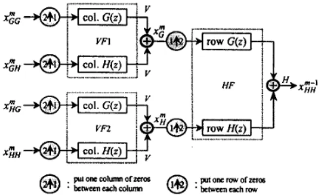
(high-high), in a separable 2-D manner as shown in Fig. 1, where x: represent external input samples for the xx band at the m-th level. Then, the foregoing procedure will be iterated to construct the next finer level of HH synthesis band, until the original signal isrestructured.
Fig. 1 One level of separable 2-D inverse DWT.
2.2
Proposed Architecture
Our proposed 2-D IDWT architecture is shown in Fig. 2. The architecture consists mainly of two vertical filters
(VF), one horizontal filter (HF), a small-size temporary buffer, and two register-banks. Assume that the horizontal
0-7803-547 1 -0/99/$10.0001999 IEEE
(row-major) filtering was performed first and then the vertical (column-major) filtering by a 2-D forward DWT to generate the decomposed signals. Given these signals as input, an inverse architecture has to perform the vertical filtering first and ithen the horizontal filtering for restoring the decomposed s~gnals to the original ones.
Horizontal Filter ovrpvro mpr I IN Vertical Filter ( V W R.nh Temporary Buffer
Fig. 2 Proposed architecture for 2-D inverse DWT.
A three-level 2-D IDWT computation-schedule scheme for the proposed architecture is shown in Fig. 3. The amount
of X's marked 011 each band in the figure denotes the
number of IDWT computations needed in one pass with a sequence of 3-2-1111-2-1111-2-1111-2-1111, where each number n represents the computation at the n-th resolution level. Thus, the to'tal number of passes needed is equal to one quarter of the amount of IDWT computations at the coarsest level.
H G ~
G G ~
Fig. 3 Diagram a three-level computation- schedule scheme.
At each level of the IDWT computation, we need four points of input-band samples to be fed into this architecture. Then, the architecture synthesizes these input samples into four output samples, which will be stored in the temporary buffer and served as the input data for the
next finer-level computation through a multiplexer. For example, at the third-level computation, we synthesize the
four input samples ( H P , HG3, GH3, GG3) into four points of
"2.
Except for the coarsest level (which uses four external input samples), we need three external samples and one internal sample that comes from a previous-level computation (the coarser level) to synthesize a finer level of output samples.According to the above discussion, the dataflow of the whole architecture is shown in Table I, where V and H
denote output samples generated by the vertical and the horizontal filters, respectively. From the table, the dash- line with arrow exhibits a relation that the horizontal output sample (H) of the previous level will become the internal input of the current level to generate the two vertical output samples ( V ) .
TABLE I
DATAFLOW OF THE PROPOSED ARCHITECTURE
In the following, we will describe the main components of
our proposed architecture in more details.
2.3 Filter Structure
For simplicity, we show only four taps of filter coefficients for all the filters in our proposed architecture in the following discussion. Moreover, since the structures of the vertical filters VFl and VF2 are the same, we only describe
VF1
in this paper., xQ (I), x&(I). x z , (0
Fig. 4 Vertical filter
(VF1).
The vertical filter
VF1
of our IDWT architecture is shown in Fig. 4. The filter contains a pair of interpolation FIR filters, which is composed of a lowpass and a highpassfilters. The input sequence of this filter takes a highpass- band sample followed by a lowpass-band sample, and this sequence is repeated until the end of input data.
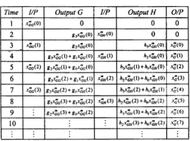
The dataflow of the vertical filter is shown in Table 11, where outputs G and H are a highpass and a lowpass
filtering outputs corresponding to the pairs of Irs in Table 1, respectively. Since output H delays one more clock cycle than output G, a delay element is added behind output G to generate the accurate synthesis samples. Clearly, the proposed vertical filter structure is efficient because it requires approximately half the hardware cost than the corresponding direct-form structures.
TABLE I1
DATAFLOW OF VERTICAL FILTER
generated by the sub-filters 0 and 0, respectively. Moreover, in Table 111, the dash-lines with arrow indicate which two filtering samples will be summated to obtain the accurate outputs, i.e.,
xgk'
which are equivalent to H in Table I.Fig. 5 Horizontal filter.
TABLE 111
DATAFLOW OF HORIZONTAL FILTER
2.4
Storage Unit
In order to deal with all the resolution levels of 2-D IDWT's, the proposed architecture needs a temporary buffer, which size is 4(m-1) for m levels. In addition, the architecture uses a highpass and a lowpass register banks in a separable 2-D filtering manner. The total size of these two register banks is approximately
NL
for processing anNxN
2-D image withL
filter length.3.
PERFORMANCE EVALUATION
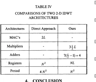
The performance data of two 2-D IDWT architectures is summarized in Table IV. For the computation of an
NxN
2-D image with a filter length
L,
a direct implementation needs about4NZ
clock cycles to compute all the levels of2-D IDWT's, and requires 2L multiplier-and-accumulator cells (MAC'S) and at least
N
*
storage unit. On the other hand, our proposed architecture spends near N clock cycles, and requires aboutNL
storage unit, 3 + L multipliers, as well as 7($-
1)+
4 adders.In addition, the function of the proposed architecture has correctly been verified by Verilog logic-level simulation.
Multipliers
1 -
TABLE
IV
COMPARJSONS OF
TWO
2-D IDWTAR.CHITECTURES
3+ L
Architectures Direct Approach
7(4
-
1)+
4Registers
-k----j+-+++
4.
CONCLUSION
Realization of a high-performance VLSI architecture for 2-D IDWT that favors the single-chip VLSI implementation has been described in this paper. The architecture utilized efficient filter structures and a computation-schedule scheme to accomplish the computations in all resolution levels. Since this architecture has a low latency, a low hardware cost, and ability to process 2-D digital signals in real-time, it can be applied very well to many real-time videohmage applications, such as MPEG-4 and PEG-2000.
5.
REFERENCES
S. Mallat, “A theory for multiresolution signal decomposition: The wavelet representation”,
IEEE Trans. Pattern Anal. and Machine Intell., vol. 1 1 , no. 7, pp. 674-693, July 1989. 0. Rioul and M. Vetterli, “Wavelets and signal processing”, IEEE Signal Processing
Magazine, vol. 8, no.4, pp. 14-38, Oct. 1991.
I. Daubechies, Ten Lectures on Wavelets, vol.
61 of CBMS-NSF Regional Conferences Series
in Applied Mathematics, SIAM, Philadelphia,
PA, 1992.
S . Mallat, “Multifrequency channel decompositions of images and wavelet models”, IEEE Trans. Acoust., Speech, Signal
Processing, vol. 37, no. 12, pp. 2091-2110,
Dec. 1989.
M. Antoniini, M . Barlaud, P. Mathieu, and I. Daubechies. “Image coding using wavelet
transform”, IEEE Trans. Image Processing, vol. 1 , no. 2, pp. 205-220, Apr. 1992.
J. M. Shapiro, “Embedded image coding using zerotrees of wavelet coefficients”, IEEE Trans. Signal Processing, vol. 41, no. 12, pp. 3445- 3462, Dec. 1993.
A. Averbuch, D. Lazar, and M. Israeli, “Image compression using wavelet transform and multiresolution decomposition”, IEEE Trans.
Image Processing, vol. 5 , no. 1, pp. 4-15, Jan. 1996.
A. S. Lewis and G. Knowles, “Video
compression using 3-D wavelet transforms”,
Electron. Lett., vol. 26, no. 6, pp. 396-398,
Mar. 1990.
K. H. Goh, J. J. Soraghan, and T. S. Durrani, “New 3-D wavelet transform coding algorithm
for image sequences”, Electron. Lett., vol. 29,
no. 4, pp. 401-402, Feb. 1993.
A. S. Lewis and G. Knowles, “VLSI
architecture for 2-D daubechies wavelet
transform without multipliers”, Electron. Lett., vol. 27, no. 2, pp. 171-173, Jan. 1991.
R. Rumian, “An architecture for real-time wavelet image decomposition”, in Proc. IEEE
Int. Symp. on Circuits and Systems, London, England, May 1994, pp. 73-76.
C. Chakrabarti, C. Mumford, “Efficient realizations of analysis and synthesis filters based on the 2-D discrete wavelet transform”,
in Proc. IEEE Int. Con$ on Acoustics, Speech,
Signal Processing, 1996, pp. 3256-3259.