Hardware Architecture Design of an H.264/AVC Video Codec
Tung-Chien Chen, Chung-Jr Lian, and Liang-Gee Chen
DSP/IC Design Lab, Graduate Institute of Electronics Engineering,
Department of Electrical Engineering, National Taiwan University, Taipei, Taiwan
(e-mail:
{djchen, cjlian, lgchen} @video.ee.ntu.edu.tw)
Abstract—H.264/AVC is the latest video coding standard. It signifi-cantly outperforms the previous video coding standards, but the extraordi-nary huge computation complexity and memory access requirement make the hardwired codec solution a tough job. This paper describes the de-sign methodology for H.264/AVC video codec. The system architecture and scheduling will be addressed. The design consideration and optimization for its significant modules including bandwidth optimized motion compen-sation engine, reconfigurable intra predictor generator, low bandwidth par-allel integer motion estimation will be mentioned. Due to the complex, sequential, and highly data-depended characteristics of all essential algo-rithms in H.264/AVC, not only the pipeline structure but also efficient mem-ory hierarchy is required. The design case with a hybrid task pipelining scheme, a balanced schedule with block-level, MB-level, and frame-level pipelining, will be presented. By combining with many bandwidth reduc-tion techniques and data reused schemes, very efficient architecture and im-plementation for plate-form based system is proved by the prototype chips.
I. INTRODUCTION
H.264/AVC is the new video coding standard. It can save 25%-45% and 50%-70% of bitrates when compared with MPEG-4 Advanced Simple Profile (ASP) [1] and MPEG-2 [2], respectively [3]. Although motion compensated transform cod-ing is still adopted, many new features are used to achieve much better compression performance and subjective quality, such as quarter-pixel Motion Estimation (ME) with Multiple Reference Frames (MRF) and Variable Block Sizes (VBS), in-tra prediction, Context-based Adaptive Variable Length Coding (CAVLC), and in-loop deblocking filter [4][5][6]. The rate-distortion optimized mode decision [3] is also included in ref-erence software [7] to improve rate-distortion efficiency.
There are many potential applications of H.264/AVC. On-going applications range from High Definition Digital Video Disc (HD-DVD) or BluRay for living room entertainment with large screens to Digital Video Broadcasting for Handheld ter-minals (DVB-H) with small screens. However, the H.264/AVC coding performance comes at the price of computation complex-ity. According to the instruction profiling with HDTV1024P (2048×1024, 30fps) specification, H.264/AVC decoding pro-cess requires 83 Giga-Instructions Per Second (GIPS) computa-tion and 70 Giga-Bytes Per Second (GBPS) memory access. As for H.264/AVC encoder, up to 3600 GIPS and 5570 GBPS are required for HDTV720P (1280×720, 30fps) specification. For real-time applications, accelerating by the dedicated hardware is a must.
However, it is difficult to design an system architecture for the H.264/AVC codec. The design for the significant modules are also very challenging. Besides high computation complexity and memory access, the coding path is very long, which includes prediction, reconstruction, and entropy coding. The reference software adopts many sequential processing of each block in the MacroBlock (MB), which restricts the parallel processing. The block-level reconstruction loop caused by intra prediction
in-duces the bubble cycles and decreases the hardware utilization and throughput. The coding tools involve with many data depen-dencies to enhance the coding performance, but the considerable storage space is the penalty. There are functionalities that have multiplex modes, and the re-configurable engine is essential to achieve resource sharing.
To address these difficulties, the hardware design methodol-ogy is described for H.264/AVC video coding system in this paper. There are three critical issues to be addressed. First, for H.264/AVC encoder, the traditional two-stage MB pipelines cannot be efficiently applied because of the long critical path and feedback loop. According to our analysis, five major func-tions are extracted and mapped into four stage MB pipelining structure with suitable task scheduling. Second, a hybrid task pipelining scheme is presented with a balanced schedule with block-level, MB-level, and frame-level pipelining to greatly re-duce the internal memory size and bandwidth. Third, the design consideration and optimization for the significant modules, in-cluding bandwidth optimized Motion Compensation (MC) en-gine, reconfigurable intra predictor generator, low bandwidth parallel IME are involved. The design cases show that efficient implementation for H.264/AVC video coding system is achiev-able by combining these efficient architectures.
The rest of this paper is organized as follows. In Section II, the profiling and the design considerations are described. Then, the architecture optimization of H.264/AVC encoding system will be addressed in Section III. Those of H.264/AVC decod-ing parts are mentioned in Section IV. These architectures are proved by the prototype chips, which will be described in Sec-tion V. Finally, we will make a conclusion in SecSec-tion VI.
II. ANALYSIS ANDDESIGNSPACEEXPLORATION
A. Profiling
We use instruction profile to show the high computation com-plexity and memory access of H.264/AVC, and find the critical parts for hardware implementation. The iprof [8], a software an-alyzer at the instruction level, is used to profile an H.264/AVC encoder at a processor-based platform (SunBlade 2000 work-station, 1.015GHz Ultra Sparc II CPU, 8GB RAM, Solaris 8). To focus on the target specification, a software C model is developed by extracting all baseline profile compression tools from reference software [7]. Our focused design case is mainly targeted for SDTV (720×480, 30fps)/HDTV720P videos with four/one reference frame. The computational complexity and memory access for SDTV/HDTV720P are 2470/3600 GIPS and 3800/5570 GBPS. As for decoder with HDTV-1024P video for-mats. 83 GIPS and 70 GBPS of computation and memory access are required. The huge computational loads are far beyond the
Block after intra prediction
Exact reconstructed pixel for intra prediction
MB-x
B-x
Block in intra prediction
For I16MB For I4MB
MB-c MB Boundary MB-a MB-b MB Boundary B-a B-d B-c B-b
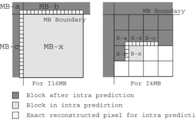
Fig. 1. (a) MB-level reconstruction loop; (b) block-level reconstruction loop. The intra prediction requires the reconstructed pixels of the left and top neighboring blocks, which induce the MB-level and block-level reconstruc-tion loops.
capability of today’s general purpose processors (GPPs). The dedicated hardware is essential for real-time applications. B. Design Space Exploration
The considerations of hardware design are analyzed with the H.264/AVC compression algorithms. The major challenges are described as follows.
• Computation Complexity and Bandwidth Requirement:
According to the profiling, H.264/AVC requires much more computation complexity than previous coding standards. this will greatly increase the hardware cost especially for the HDTV applications. The bandwidth requirement of H.264/AVC encod-ing system is also much higher than previous codencod-ing standard. The MRF-ME contributes the most traffic for loading reference pixels. Neighboring reconstructed pixels are required by intra prediction, and are also required by deblocking filter. Besides, Lagrangian mode decision and context-adaptive entropy coding have data dependencies between neighboring MB, and transmit-ting related information contribute considerable bandwidth as well. An efficient memory hierarchy combined with data shar-ing and Data Reuse (DR) scheme must be designed to reduce the system bandwidth.
• Sequential Flow: The H.264/AVC reference software adopts
many sequential process to enhance the compression perfor-mance. It is hard to efficiently map the sequential algorithm to parallel hardware. For system architecture, we partition the se-quential encoding process ( prediction, reconstruction, and then entropy encoding ) into several tasks and process them in MB-based pipelining structure, which improves the hardware utiliza-tion and the throughput. For module architecture, this problem is critical for ME since ME is the most computationally inten-sive part and requires the most degrees of parallelism. The inter Lagrangian mode decision takes MV costs into consideration. The MV of each block is generally medium predicted by left, top, and top-right neighboring blocks. The cost function can be computed only after prediction modes of neighboring blocks are determined, which also causes inevitable sequential processing. The modified hardware-oriented algorithms can be designed to enable parallel processing.
• Coding Loops: In traditional video coding standard, there
is a frame-level reconstruction loop generating the reference frames for ME and MC. In H.264/AVC, the intra prediction re-quires the reconstructed pixels of the left and top neighboring blocks, which induce the MB-level and block-level reconstruc-tion loops. For the MB-level reconstrucreconstruc-tion loop as shown in Fig. 1 (a), the reconstructed pixels of a, b, and MB-c are used to prediMB-ct the pixels in MB-x for I16MB. Not until MB-a, MB-b, and MB-c are reconstructed can MB-x be pre-dicted. Similarly, as Fig. 1 (b) shows, in order to support I4MB, not until 4×4-intra mode of B-a, B-b, B-c, and B-d are decided and reconstructed can B-x be processed. The reconstructed la-tency is harmful to hardware utilization and throughput if the in-tra prediction and reconstruction are not jointly considered and scheduled.
• Data Dependency: The new coding tools improve the
com-pression performance with many data dependencies. The frame-level data dependencies contribute the considerable system bandwidth. The dependencies between neighboring MBs con-strain the solution space of MB pipelining, and those between neighboring blocks limit the possibility of parallel processing.
• Abundant Modes: There are many algorithms of H.264/AVC
that have multiplex modes. For example, there are 17 differ-ent modes for intra prediction while 259 kinds of partitions for inter prediction. Six kinds of 2-D transform, 4×4/2×2 DCT/IDCT/Hadamard transform, are involved in reconstruction loops. The reconfigurable processing engine, reusable predic-tion core, and appropriate pipeline system design are important to efficiently support all these functions.
C. Related Works
The conventional two-stage MB pipelining architecture [9][10] is widely adopted in prior video encoding hardware de-signs. Two MBs are processed simultaneously by prediction en-gine (ME only) and Block Enen-gine (BE, including MC, recon-struction loop, and entropy coding) in pipeline manner. Several problems will be encountered if the two-stage MB pipelining is directly applied to H.264/AVC encoding. The prediction stage includes IME, FME, and intra prediction in H.264/AVC. The sequential prediction flow will make high operation frequency and low hardware utilization. Besides, because of MB-level and block-level reconstruction loops, it is impossible to completely separate the prediction and BE stages. The large bandwidth must also be reduced by efficient memory hierarchy and data reuse scheme.
Furthermore, because of the new funcationalities of H.264/AVC, the advanced module architectures are demanded for H.264/AVC encoder. IME is the most computationally in-tensive part in the encoder. Several IME architectures are pro-posed for VBSME [11] [12] [13][14] with different specifica-tions. The main challenge for FME is to achieve parallel pro-cessing under the constraints of sequential Lagrangian mode decision. Besides, the functionalities of the VBS, MRF, 6-tap FIR, and Hadamard transform are involved. In [15], FME pro-cedure is analyzed and decomposed into several loops. The fully pipelined architecture is designed with unfolding tech-niques and efficient scheduling. In [16], the forward/inverse multi-transform are designed to support 4×4 DCT, IDCT, and Hadamard transforms. The first deblocking filter propose the
ad-Rec. MB
SRAM Deblock SRAM Residue MB
SRAM
Bitstream SRAM
Luma Ref. Pels SRAMs
Cur. Luma & Chroma MB SRAM
MC Luma MB SRAM
Main Controller System Bus Interface
Local Bus Interface Upper Ref. & MV SRAM
Cur. Luma MB Reg.
MC Chroma MB SRAM Upper Pels & I4MB
SRAM
Total Coeff. SRAM
Upper MB QP & Intra Flag SRAM
IME Engine FME Engine Encoder Chip
1st Stage 2nd Stage 3rd Stage 4th Stage
EC Engine DB Engine IP Engine 3MB Local External Memory (Ref. Frames)
AHB Master/Slave DRAM Controller AHB
RISC
Video Input System External
Memory
Fig. 2. Block diagram of the H.264/AVC encoding system. Five major tasks, including IME, FME, IP, EC, and DB, are partitioned from the sequential encoding procedure and processed MB by MB in pipeline structure.
vanced filtering schedule to save 50% on-chip bandwidth [17]. A column addressing technique used to favor the direction of vertical filtering is then proposed in [18] to increase the through-put. In [19], the architecture is further improved by interleav-ingly filtering the the horizontal and vertical edges. As for entropy encoder, the single buffer CAVLC architecture [20] is designed for SDTV specification. The dual-buffer architecture with block pipelining is proposed in [21] to double the hardware utilization and throughput.
III. H.264/AVC ENCODINGSYSTEM
This section describes a new MB pipelining scheme for H.264/AVC encoder. The traditional two-stage MB pipelining [9][10], prediction (ME only) and BE, cannot be efficiently ap-plied to H.264/AVC. In this encoding system, five major func-tions are extracted and mapped into four MB pipelining stages with suitable task scheduling [22]. Furthermore, the design con-sideration and optimization for the significant modules is de-scribed to enable the whole system. The efficient implementa-tion for H.264/AVC encoding system is achieved by combining these techniques.
A. Four-Stage Macroblock Pipelining
The system architecture is shown in Fig. 2. Five major tasks, including IME, FME, Intra Prediction with reconstruction loop (IP), Entropy Coding (EC), and in-loop DeBlocking filter (DB), are partitioned from the sequential encoding procedure and pro-cessed MB by MB in pipeline structure.
Several issues are described as follows. The prediction, which is ME only in previous standards, includes IME, FME, and in-tra prediction in H.264/AVC. Because of the algorithms diver-sities and different computation complexity, it is difficult to im-plement IME, FME, and intra prediction by the same hardware. Putting IME, FME, and intra prediction in the same MB pipelin-ing stage leads to very low utilization. Even if the resource sharing is achieved, the operating frequency becomes too high due to the sequentially processing. Therefore, FME is firstly pipelined MB by MB after IME to double the throughout. As for intra prediction, because of MB-level and block-level
recon-B1 B2 B3 B1 B2 B3 B1 B1 B2 B3 B2 B1 B1 B3 B2 B4 B4 B4 First MB Row Time Line IME FME INTRA EC / DB
....
....
....
Tasks B2 B4 B3 Second MB Row B1 B2 B4 B1 B2 B3 B3 B4 B1 B1....
....
Fig. 3. The MB schedule of four stage MB pipelining. The horizontal arrow de-notes the time line. One horizontal column indicates the MBs with different tasks that are processed in parallel.
struction loop, it cannot be separated with the reconstruction en-gine. Besides, the reconstruction process should be separated from ME and pipelined MB by MB to achieve highest hard-ware utilization. Therefore, engines of intra prediction together with forward/inverse transform/quantization should be located in the IP stage. In this way, the MB-level and block-level re-construction loops can also be isolated in this pipelining stage. The EC encodes the MB header and residues after mode deci-sion and prediction. The DB generates the standard-compliant reference frame after reconstruction. Since the EC/DB can be processed in parallel, they are placed at the 4th stage. The ref-erence frame will be stored in external memory for the ME of the next frame, which constructs the frame-level reconstruction loop. Please note that, the luma MC is placed in FME stage for reuse ofLuma Ref. Pels SRAMs and interpolation circuits. The compensated MB is transmitted to IP stage for generation of residues after intra/inter mode decision. On the other hand, chroma MC is implemented in IP stage since it is not required before intra/inter mode decision.
MBs within one frame are coded in raster order with sched-ule in Fig. 3. The horizontal arrow denotes the time line. One horizontal column indicates the MBs with different tasks that are processed in parallel. As for reduction in system bandwidth, many on-chip memories are used for three purposes. First, in
order to find the best matched candidate, a huge amount of ref-erence data are required for both IME and FME. Since pixels in neighboring candidate blocks are considerably overlapped, and so are the SWs of neighboring current MBs, the bandwidth of system bus can be greatly reduced by designing local buffers to store reusable data. Second, instead of transmitted by sys-tem bus, the raw data such as luma motion compensated MB, transformed and quantized residues, and reconstructed MB are shifted forward via shared memories. Third, because of data dependency, a MB is processed according to the upper and left MBs. The local memories are used to store the related data dur-ing the encoddur-ing process. For software implementation, the ex-ternal bandwidth requirement is up to 5570 TBPS. As for hard-ware solution with local search window buffer embedded, the external bandwidth requirement is reduced to 700 MBPS. Af-ter all three techniques are applied, the final exAf-ternal bandwidth requirement is about 280 Mbytes/sec.
B. Low-Bandwidth Parallel Integer Motion Estimation IME requires the most computational complexity and mem-ory bandwidth in H.264/AVC. Besides, it is a kind of sequen-tial flow due to the Lagrangian mode decision flow. However, a large degree of parallelism is required for the SDTV/HDTV specifications. In the following, techniques in algorithmic and architectural levels are used to enable parallel processing and to reduce the required hardware resources.
B.1 Hardware-Oriented Algorithm
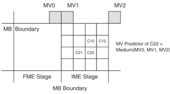
The Motion Vector (MV) of each block is generally predicted by the medium values of MVs from the left, top, and top right neighboring blocks. The rate term of the Lagrangian cost func-tion can be computed only after MVs of neighboring blocks are determined, which causes inevitable sequential processing. The blocks and subblocks in a MB cannot be processed in paral-lel. Moreover, when a MB is processed at the IME stage, its previous MB is still in the FME stage. The MB mode and the best MVs of the left MB cannot be obtained in the four-stage MB pipelining architecture. To solve these problems, the exact MVPs are replaced by modified MVPs, which is the medium of MVs from top-left, top, and top-right MBs. In addition, the modified MVP is applied for all of the 41 blocks in MB, as shown in Fig. 4. For example, the exact MV cost of the C22 4×4-block is the medium of the C12, C13, and C21 MVs. The MVPs of all 41 blocks are changed to the medium of MV0, MV1, and MV2 in order to facilitate the parallel processing and MB pipelining.
As for searching algorithm, FS is adopted to guarantee the highest compressing performance. The regular searching pat-tern is suitable for parallel processing. Besides, FS can effec-tively support VBS by reusing each 4×4-block SADs for larger blocks. Pixel truncation [23] of five-bit precision and subsam-pling [24] of half pixel rate are applied to reduce the hardware cost. Moreover, adaptive search range adjustment [25] is also applied to save computations.
B.2 Architectures Design of IME
In IME, in order to find the best matched candidate, a Search Window (SW) within one reference frame has to be searched.
C12 C13 C21 C22
MV0 MV1 MV2
MB Boundary
MB Boundary FME Stage IME Stage
MV Predictor of C22 = Medium(MV0, MV1, MV2)
Fig. 4. Modified MVPs. In order to facilitate the parallel processing and MB pipelining, the MVPs of all 41 blocks are changed to the medium of MV0, MV1, and MV2.
Router
41-Parallel Eight-Input Comparator Tree Array RefMV
Buffer
Cur. MB Reg. Ref. Pels Reg. Array Cur. Luma MB Pels
(from System Bus) Ref. & MV Info.
(Update by IP)
Search Area Pels (from Local Bus)
Integer MV Buffer (41 MVs per Ref. Frame) Encoding Parameters (from Main Control)
41 MVs
41 SADs 41 SADs 41 SADs
PE-Array SAD Tree #0 PE-Array SAD Tree #1 PE-Array SAD Tree #7 MV Cost Gen. . . . . . .
...
Luma Ref. Pels SRAMs Upper Ref. &
MV SRAM
On-Chip Padding IME
Controller
Fig. 5. Block diagram of the low bandwidth parallel IME engine. It mainly comprises eightPE-Array 2-D SAD Tree, and eight horizontally adjacent candidates are processed in parallel.
Figure 5 shows the low bandwidth parallel IME architecture, which mainly comprises eight PE-Array 2-D SAD Tree. The Current MB (CMB) is stored inCur. MB Reg. The reference pixels are read from external memory and stored inLuma Ref. Pels SRAMs. Each PE array and its corresponding 2-D SAD tree compute the 41 SADs of VBS for one searching candidate each cycle. Therefore, eight horizontally adjacent candidates are processed in parallel.
Because SWs of neighboring current MBs are consider-ably overlapped, and so are the pixels of neighboring candi-date blocks, a three-level memory hierarchy, including exter-nal memory, Luma Ref. Pels SRAMs, and Ref. Pels Reg. Array, is used to reduce bandwidth requirement by data reuse (DR). Three kinds of DR are implemented—MB-level DR, inter-candidate DR, and intra-candidate DR. The Luma Ref. Pels SRAMs are firstly embedded to achieve MB-level DR. when ME process is changed from one CMB to another CMB, there are overlapped area between neighboring SWs. Therefore, only a part of SW must be loaded from system memory, and the system bandwidth can be reduced [26].
The Ref. Pels Reg. Array acts as the cache between PE-Array 2-D SAD Tree and Luma Ref. Pels SRAMs. It is de-signed to achieve inter-candidate DR. A horizontal row of ref-erence pixels, which is read from SRAMs, is stored and shifted
Current Macroblock Array
Reference Pixel Array 256-PE Array (128 if sub-sample) Shift Direction 16x16-SAD 16 2-D Adder Sub Trees for 4x4-Blocks One VBS Tree for Larger Blocks 2-D
SAD Tree
Row of 16 Ref. Pel
Data Path Adder Tree
PE (Sub.+Abs.) Reg.
Fig. 6. PE-array 2-D SAD Tree architecture. The costs of sixteen 4×4-blocks are separately summed up by sixteen2-D Sub-trees, and then reused by one VBS Tree for larger blocks.
downward inRef. Pels Reg. Array. When one candidate is pro-cessed, 256 reference pixels are required. When eight horizon-tally adjacent candidates are processed in parallel, not (256×8) but (256+16×7) reference pixels are required. Besides, when the ME process is changed to the next eight candidates, most data can be reused inRef. Pels Array. The parallel architec-ture achieves inter-candidate DR in both horizontal and vertical directions and reduce the on-chip SRAM bandwidth.
Fig. 6 shows the architecture ofPE-array 2-D SAD Tree. The costs of sixteen 4×4-blocks are separately summed up by six-teen2-D Sub-trees, and then reused by one VBS Tree for larger blocks. This is so-called intra-candidate DR. All 41 SADs for one candidate are simultaneously generated and compared with the 41 best costs. No intermediate data are buffered. There-fore, this architecture can support VBS without any partial SAD registers.
C. Reconfigurable Intra Predictor Generator
The intra prediction supports the most various prediction modes, which includes four I16MB modes, night I4MB modes, and four Chorma modes. For the RISC-based solution, the re-quired operation frequency will become too high. For the ded-icated hardware, 17 kinds of PEs for the 17 modes make the hardware cost high. Therefore, the reconfigurable circuit and resource sharing for all intra prediction modes are the efficient solutions.
The hardware architecture of the four-parallel reconfigurable intra predictor generator is shown in Fig. 7. Capital letters (A, B, C, ...) are the neighboring 4×4-block pixels. UL, L0-L15, and U0-U15 denote the bottom right pixel from the up-per left MB, the 16 pixels of the right most column from the left MB, and the 16 pixels of the bottom row from the upper MB, respectively. Four different configurations are designed to support all intra prediction modes in H.264/AVC. Firstly, the I4MB/I16MB horizontal/vertical modes use the bypass data path to select the predictors extended from the block boundaries.
D0
MUX
Round & Shift
Clip
MUX MUX MUX MUX
MUX Round & Shift Clip MUX Round & Shift Clip MUX Round & Shift Clip MUX IJKLM ABCDE FGH IJKLM ABCDE FGH IJKLM ABCDE FGH IJKLM ABCDE FGH
MUX MUX MUX
Predictor Output 0 Predictor Output 1 Predictor Output 2 Predictor Output 3 Cascade Configuration Bypass Configuration Accumulation Configuration UL, U_0-15 L_0-15 D2 D3 D1 D0-3 D0-3 D0-3 D0-3 UL, U_0-15 L_0-15 UL, U_0-15 L_0-15 UL, U_0-15 L_0-15
Fig. 7. Four-parallel reconfigurable intra predictor generator. Four differ-ent configurations are designed to support all intra prediction modes in H.264/AVC.
Secondly, multiple PEs are cascaded to sum up the DC value for I4MB/I16MB/chroma DC mode. Thirdly, the normal configu-ration is used for I4MB directional modes 3–8. The four PEs select the corresponding pixels multiple times according to the weighted factors, and process independently. Finally, the recur-sive configuration is designed for I16MB plan prediction. The predictors are generated by adding the gradient values to the re-sult of previous cycles.
IV. H.264/AVC DECODINGSYSTEM
In this section, a methodology to determine a suitable pipelin-ing structure of a H.264/AVC decoder is presented. The target resolution is HDTV1024P 30fps videos. The design goals of this work are low area cost and low system bandwidth. In the following sections, the scheduling as well as the key modules of the decoding system will be elaborated.
A. Hybrid Task Pipelining
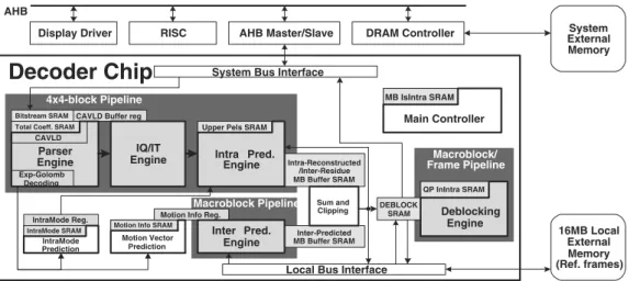
The overall system architecture is shown in Fig. 8 [27]. The sequence parameter set, picture parameter set, and slice head-ers are parsed by system processor. The MB-level information including MB headers and transformed/quantized residues are decoded by theParser Engine. The predicted pixels are gener-ated by theInter Pred. Engine or Intra Pred. Engine according to the MB mode. The residues are recovered by theIQ/IT Engine. The MB is reconstructed bySum and Clipping Engine. Finally, Deblocking Engine filters MB pixels and outputs them to the ex-ternal memory. The buffers between the processing engines are required to separate pipelining stages.
Previous designs of video decoders are usually based on MB pipelining scheme [28]. Our system architecture is based on a hybrid task pipelining scheme including 4×4-block-level pipelining, MB-level pipelining, and frame-level pipelining. The reasons are stated as following. In H.264/AVC, 4×4-block is the smallest element of the prediction block mode. The transforms and entropy coding are also based on 4×4-blocks.
Intra-Reconstructed /Inter-Residue MB Buffer SRAM
Inter-Predicted MB Buffer SRAM CAVLD Buffer reg
IQ/IT Engine
Inter Pred. Engine
Upper Pels SRAM
DEBLOCK SRAM
QP InIntra SRAM
Motion Info SRAM IntraMode SRAM
Motion Vector Prediction IntraMode
Prediction
IntraMode Reg. Motion Info Reg.
MB IsIntra SRAM Intra Pred. Engine Exp-Golomb Decoding Parser Engine CAVLD
Total Coeff. SRAM Main Controller
Local Bus Interface 4x4-block Pipeline Macroblock Pipeline Macroblock/ Frame Pipeline 16MB Local External Memory (Ref. frames) Bitstream SRAM
System Bus Interface
Display Driver RISC AHB Master/Slave DRAM Controller ExternalSystem Memory AHB
Decoder Chip
Sum and Clipping Deblocking EngineFig. 8. Hybrid task pipelining system architecture.
Therefore, a 4×4-block pipelining scheme can be designed for CAVLD, inverse quantization/inverse transformation, and in-tra prediction with the benefit of less coding latency. It re-quires about 1/24 of buffer size compared to the traditional MB pipelining architecture.
Inter prediction produces the predicted MB pixels from pre-viously decoded reference frames. As with intra prediction, the basic processing element of inter prediction is also a 4×4-block. Due to the six-tap FIR filter for interpolation, 9×9 integer refer-ence pixels are required for a current 4×4-block. If the blocks of prediction mode are larger than 4×4, overlapped reference frame pixels of these 4×4-blocks can be reused to reduce the system bandwidth. The inherent order of 4×4-blocks in the bit-stream is the double-z-scan order. Reference frame DR will be less efficient ifInter Pred. Engine adopts the 4×4-block pipelin-ing scheme and follows the double-z-scan order. Therefore, In-ter Pred. Engine should be scheduled to MB-level pipelining with a customized scan order to exploit the reference frame DR. All reference pixels necessary to predict a MB are read from memory at once to reduce memory bandwidth.
Deblocking Engine is another special case that does not suit to the double-z scan order.Deblocking Engine filters the edges of each 4×4 block vertically then horizontally. Besides, one 4×4-block cannot be completely filtered until its neighboring 4×4-blocks are reconstructed. This data dependency makes it impractical to fit the deblocking operation into a 4×4-block pipelining, since the buffer cannot be efficiently reduced and serious control over-head is required. If the decoder has to support FMO and ASO, where the MBs of a frame may not be coded in raster-scan or-der, the DB unit has to be scheduled to frame level pipelining because the filtering order of one frame can not either be vio-lated in MB boundaries. Otherwise, the MB pipelining schedule is adopted.
B. Low-bandwidth Motion Compensation Engine
According to the analysis in decoder system, MC should be scheduled to MB-level pipelining with a customized scan order to exploit the reference frame DR. The 4×4-based MC is firstly adopted. All VBS are decomposed into several 4×4 element
9 9 Reference frame 4x4 block 4 5 4 4 4 5 Reference frame 8x8 block 9 4 Reference frame 4x4 block (a) (b) (c)
Fig. 9. (a) General case interpolation window; (b) Four interpolation windows for an 8×8 block (shaded region means reusable); (c) Interpolation window when MV pointing to horizontal integer pixels.
blocks, and processed by the MC engine with full hardware uti-lization. The straightforward memory access scheme processes every decomposed 4×4 element blocks independently, and al-ways loads 9×9 pixels for interpolation as shown in Fig. 9(a). The bandwidth requirement of 4×4-based MC can be reduced by two bandwidth reduction techniques [29].
The first technique is Interpolation Window Reuse (IWR). As shown in Fig. 9(b), there are overlapped regions between interpolation windows for neighboring 4×4 element blocks when the block mode is larger than 4×4. The shaded regions can be reused. The second scheme is Interpolation Window Classification (IWC). The interpolation window is not always (X+5)×(Y+5) for a X×Y block. As shown in Fig. 9(c), a 4×4 block with integer MV in horizontal direction does not require horizontal filtering. A 4×9 interpolation window is read. In brief, the IWR and IWC scheme aim to precisely control the MC hardware to load a smaller and exact interpolation window. These techniques can provide about 60–80% bandwidth reduc-tion for the 4×4-based MC.
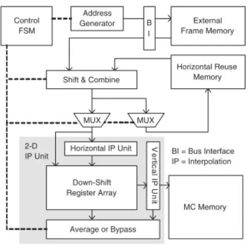
Figure 10 shows the MC architecture. The efficient vertical scheduling in [15] is applied with Down Shift Register Array to support vertical IWR. Besides, anHorizontal Reuse Memory is designed for horizontal IWR. The IWC is implemented by Control FSM and Address Generator. The Shift & Combine circuit packs the required integer pixels inputted from external frame memory andHorizontal Reuse Memory. The 2-D IP Unit performs the interpolation, and the compensated MB is buffered in the MC memory.
Address Generator Control FSM BI = Bus Interface IP = Interpolation External Frame Memory
Shift & Combine
MC Memory MUX Horizontal Reuse Memory MUX Horizontal IP Unit Down-Shift Register Array V e rt ic a l IP U n it Average or Bypass B I 2-D IP Unit
Fig. 10. Block diagram of MC hardware. TABLE I
HARDWARERESOURCE OFH.264/AVC ENCODER
Functional Block Gate Counts Memory (KB)
IME Module 305211 13.71 FME Module 401885 13.82 IP Module 121012 5.01 EC Module 29332 1.27 DB Module 20152 0.91 Others 45176 0.00 Total 922768 34.72 V. IMPLEMENTATIONRESULTS
A. Implementation results of H.264/AVC SDTV/HDTV720P En-coder
The specification of this H.264/AVC encoder is baseline pro-file with level up to 3.1. The maximum computational capa-bility is to real-time encode SDTV 30fps video with four ref-erence frames or HDTV720P 30fps video with one refref-erence frame. Table I shows the logic gate count profile synthesized at 120 MHz. The total logic gate count is about 922.8K. The prediction engine, including IME, FME, and IP stages, domi-nates 90% of logic area. As for on-chip SRAM requirement, 34.88 KB are required. The chip is fabricated with UMC 0.18 µm 1P6M CMOS process. Figure 11 shows the die micrograph. The core size is 7.68×4.13 mm2. The power consumption is 581 mW for D1 videos and 785 mW for HDTV720p videos at 1.8 V supply voltage with 81/108 MHz operating frequency. The
TABLE II
SPECIFICATION OF THEDEVELOPEDH.264/AVC BASELINEPROFILE
ENCODERCHIP
Technology UMC 0.18 µm 1P6M CMOS
Pad/Core Voltage 3.3/1.8 V
Core Area 7.68×4.13 mm2
Logic Gates 922.8 K (2-input NAND gate)
SRAM 34.72 KB
Operating Frequency 81/108 for D1/HDTV720P
Power Consumption 581/785 mW for D1/HDTV720P
Encoding Features All Baseline Profile Compression Tools
Max. # of Ref. Frames 4/1 for D1/HDTV720P
Max. SR (Ref. 0) H[-64,+63] V[-32,+31]
Max. SR (Ref. 1-3) H[-32,+31] V[-16,+15]
TABLE III
GATECOUNTPROFILE OFTHEH.264/AVC DECODER
Functional Block Gate Counts Memory (KB)
Main Control 22695 0.48
Parser Engine 21121 1.02
Inter Pred. Engine 69695 2.43
Intra Pred. Engine 28707 4.93
IQ/IT Engine 19792 0.00
Deblocking Engine 35437 1.12
Others 19980 0.00
Total 217428 9.98
TABLE IV
CHIPFEATURES OFH.264/AVC DECODER
Technology TSMC 0.18 µm 1P6M CMOS
Pad/Core Voltage 3.3/1.8 V
Core Area 2.19×2.19 mm2
Logic Gates 21.743 K (2-input NAND gate)
SRAM 9.98 KByte
Profile Baseline
Operating Frequency 120/1.5 MHz for HDTV1024P 30fps/QCIF 15fps
Power Consumption 186.4/1.18 mW for HDTV1024P 30fps/QCIF 15fps
detailed chip features are shown in Table II.
B. Implementation results of H.264/AVC HDTV1024P Decoder The specification of this H.264/AVC decoder is baseline pro-file with level 4.1. It can real-time decode HDTV1024P 30fps video with operational frequency of 120 MHz. Table III shows the hardware resource requirement. The total logic gate count is 217K, and the on-chip SRAM requirement is 10 KB. The chip is fabricated with TSMC 0.18µm 1P6M CMOS technol-ogy. The core size is 2.19×2.19 mm2. The power consumption
is 186.4 mW at 1.8V and 120MHz for decoding HDTV1024P 30fps videos, and is 1.18 mW at 1.8V and 1.5MHx for decoding QCIF (176×144) 15fps videos. The detailed chip features are shown in Table IV.
VI. CONCLUSION
In this paper, state-of-the-art hardware architectures for H.264/AVC video coding core have been presented. First, five major functional blocks are mapped into four-stage MB pipelin-ing structure to highly increase the processpipelin-ing capability and hardware utilization. Besides, a hybrid task pipelining scheme, a balanced schedule with block-level, MB-level, and frame-level pipelining, is used for decoder to greatly reduce the internal memory size. Combined with many bandwidth reduction tech-niques and DR schemes, these two system architectures are all characterized by high throughput and low system bandwidth re-quirement. Moreover, efficient modules are designed to sup-port the new H.264/AVC functionalities. A parallel IME archi-tecture comprising eight PE arrays and adder trees is applied to dramatically reduce the memory bandwidth by three-level memory hierarchy and DR scheme. A reconfigurable intra pre-dictor generator was designed to achieve resource sharing for all intra prediction modes. A bandwidth optimized MC engine highly exploits DR between interpolation windows of neighbor-ing blocks. The hardwired codneighbor-ing system can efficiently support HDTV videos with real-time constraint, which is proved by the
IME
FME
Luma Ref0 Pels SRAMsLuma Ref1-3 Pels SRAMs Luma Ref1-3 Pels SRAMs
IP
EC
DB
SRAMs SRAMs SRAMsFig. 11. Die micrograph of the H.264/AVC encoder [30].
prototype chips.
REFERENCES
[1] Information Technology - Coding of Audio-Visual Objects - Part 2: Visual, ISO/IEC 14496-2, 1999.
[2] Information Technology - Generic Coding of Moving Pictures and Associ-ated Audio Information: Video, ISO/IEC 13818-2 and ITU-T Rec. H.262, 1996.
[3] T. Wiegand, H. Schwarz, A. Joch, F. Kossentini, and G. J. Sullivan, “Rate-constrained coder control and comparison of video coding standards,” IEEE Transactions on Circuits and Systems for Video Technology, vol. 13, no. 7, pp. 688–703, July 2003.
[4] T. Wiegand, G. J. Sullivan, G. Bjøntegaard, and A. Luthra, “Overview of the H.264/AVC video coding standard,” IEEE Transactions on Circuits and Systems for Video Technology, vol. 13, no. 7, pp. 560–576, July 2003. [5] J. Ostermann, J. Bormans, P. List, D. Marpe, M. Narroschke, F. Pereira, T. Stockhammer, and T. Wedi, “Video coding with H.264/AVC: tools, performance, and complexity,” IEEE Magazine on Circuits and Systems Magazine, vol. 4, pp. 7–28, 2004.
[6] Atul Puri, Xuemin Chen, and Ajay Luthra, “Video coding using the
H.264/MPEG-4 AVC compression standard,” Signal Processing: Image Communication, vol. 19, pp. 793–849, Oct. 2004.
[7] Joint Video Team Reference Software JM7.3, http://bs.hhi.de/ suehring/tml/download/, Aug. 2003.
[8] ftp://ftp.lis.e-technik.tu muenchen.de/pub/iprof/, “Iprof ftp server,” .
[9] M. Takahashi and et.al., “A 60-MHz 240-mW MPEG-4 videophone LSI
with 16-Mb embedded DRAM,” IEEE Journal of Solid-State Circuits, vol. 35, pp. 1713–1721, Nov. 2000.
[10] H. Nakayama and et.al., “A MPEG-4 video LSI with an error-resilient codec core based on a fast motion estimation algorithm,” in Proceedings of IEEE International Solid-State Circuits Conference (ISSCC’02), Feb. 2005, vol. 2, pp. 296–512.
[11] Y.-W. Huang, T.-C. Wang, B.-Y. Hsieh, and L.-G. Chen, “Hardware ar-chitecture design for variable block size motion estimation in MPEG-4 AVC/JVT/ITU-T H.264,” in Proceedings of IEEE International Sympo-sium on Circuits and Systems (ISCAS’03), 2003, pp. 796–799.
[12] J.-H. Lee and N.-S. Lee, “Variable block size motion estimation algorithm and its hardware architecture for H.264,” in Proceedings of IEEE Interna-tional Symposium on Circuits and Systems (ISCAS’04), May 2004, vol. 3, pp. 740–743.
[13] Swee Yeow Yap and J. V. McCanny, “A VLSI architecture for variable block size video motion estimation,” IEEE Transactions on Circuit and System II, vol. 51, pp. 384–389, 2004.
[14] Minho Kim, Ingu Hwang, and Soo-Ik Chae, “A fast vlsi architecture for full-search variable block size motion estimation in MPEG-4 AVC/H.264,” in Proc. of 2005 Asia and South Pacific Design Automation Conference, Jan. 2005, vol. 1, pp. 631–634.
[15] T.-C Chen, Y.-W. Huang, and L.-G. Chen, “Fully utilized and reusable architecture for fractional motion estimation of H.264/AVC,” in Proceed-ings of IEEE International Conference on Acoustics, Speech, and Signal Processing (ICASSP’04), 2004, pp. V9–V12.
[16] T.-C. Wang, Y.-W. Huang H.-C. Fang, and L.-G. Chen, “Parallel 4x4 2D transform and inverse transform architecture for MPEG-4 AVC/H.264,” in
Proceedings of IEEE International Symposium on Circuits and Systems (ISCAS’03), 2003, pp. 800–803.
[17] Y.-W. Huang, T.-C. Wang, B.-Y. Hsieh, T.-C. Wang, T.-H. Chang, and L.-G. Chen, “Architecture design for deblocking filter in H.264/JVT/AVC,” in Proceedings of IEEE International Conference on Multimedia and Expo (ICME’03), 2003, pp. I693–I696.
[18] S.-Y Shih, C.-R. Chang, and Y.-L. Lin, “An AMBA-compliant deblocking filter IP for H.264/AVC,” in submission to IEEE International Symposium on Circuits and Systems (ISCAS’05), 2004.
[19] Tsu-Ming Liu, Wen-Ping Lee, and Chen-Yi Lee, “An area-efficient and high-throughput de-blocking filter for multi-standard video applications,” in Proceedings of IEEE International Conference on Image Processing (ICIP’05), 2005, pp. III–1044–1047.
[20] Y.-W. Huang, B.-Y. Hsieh, T.-C. Chen, , and L.-G. Chen, “Analysis, fast algorithm, and vlsi architecture design for H.264/AVC intra frame coder,” IEEE Transactions on Circuits and Systems for Video Technology, 2004. [21] T.-C. Chen, Y.-W. Huang, C.-Y. Tsai, , and L.-G. Chen,
“Dual-block-pipelined VLSI architecture of entropy coding for H.264/AVC baseline profile,” in Proceedings of IEEE International Symposium on VLSI De-sign, Automation and Test (VLSI-TSA-DAT’05), 2005, pp. 271–274. [22] T.-C Chen, Y.-W. Huang, and L.-G. Chen, “Analysis and design of
mac-roblock pipelining for H.264/AVC VLSI architecture,” in Proceedings of 2004 International Symposium on Circuits and Systems (ISCAS’04), 2004, pp. II273–II276.
[23] Z.-L. He, C.-Y. Tsui, K.-K. Chan, and M.-L. Liou, “Low-power VLSI de-sign for motion estimation using adaptive pixel truncation,” IEEE Trans-actions on Circuits and Systems for Video Technology, vol. 10, no. 5, pp. 669–678, Aug. 2000.
[24] B. Liu and A. Zaccarin, “New fast algorithms for the estimation of block motion vectors,” IEEE Transactions on Circuits and Systems for Video Technology, vol. 3, no. 2, pp. 148–157, Apr. 1993.
[25] S. Saponara and L. Fanucci, “Data-adaptive motion estimation algorithm and VLSI architecture design for low-power video systems,” Proc. IEE on Computers and Digital Techniques, vol. 151, pp. 51–59, 2004.
[26] J.-C. Tuan, T.-S. Chang, and C.-W. Jen, “On the data reuse and mem-ory bandwidth analysis for full-search block-matching VLSI architecture,” IEEE Transactions on CSVT, vol. 12, pp. 61–72, Jan. 2002.
[27] T.-W. Chen, Y.-W. Huang, T.-C. Chen, Y.-H. Chen, C.-Y. Tsai, and L.-G. Chen, “Architecture design of H.264/AVC decoder with hybrid task pipelining for high definition videos,” in Proceedings of 2005 Interna-tional Symposium on Circuits and Systems (ISCAS’05), 2005, pp. 2931– 2934.
[28] H.-Y. Kang, K.-A. Jeong, J.-Y. Bae, Y.-S. Lee, and S.-H. Lee, “MPEG4 AVC/H.264 decoder with scalable bus architecture and dual memory con-troller,” in Proc. of Int. Symposium on Circuits and Systems (ISCAS’04), 2004.
[29] C.-Y. Tsai, T.-C. Chen, T.-W. Chen, , and L.-G. Chen, “Bandwidth opti-mized motion compensation hardware design for H.264/AVC HDTV de-coder,” in Proceedings of 2005 International Midwest Symposium on Cir-cuit and Systems (MWSCAS’05), 2005.
[30] Y.-W. Huang and etc., “A 1.3TOPS H.264/AVC Single-Chip Encoder for HDTV Applications,” in Proceedings of IEEE International Solid-State Circuits Conference (ISSCC’05), 2005, pp. 128–130.


![Fig. 11. Die micrograph of the H.264/AVC encoder [30].](https://thumb-ap.123doks.com/thumbv2/9libinfo/8863240.245793/8.892.238.705.114.370/fig-die-micrograph-h-avc-encoder.webp)
