460 IEEE TRANSACTIONS O N INDUSTRIAL ELECTRONICS, VOL. 39, NO. 5, OCTOBER 1992
Letters to the Editor
An Optimal Variable Structure Control withIntegral Compensation for Electrohydraulic Position Servo Control Systems Tzuen-Lih Chern and Yung-Chun WU
Abstrac-An approach employing variable structure control with inte- gral compensation is presented for an electrohydraulic position servo control system to achieve accurate servo tracking in the presence of load disturbance and plant parameter variation. Simulations show that the proposed approach may give a rather accurate servo-tracking result and is fairly robust to plant parameter variation and load disturbance.
I. INTRODUCTION
Processes requiring large driving forces or torques are often actuated by hydraulic servo systems. The dynamic characteristics of such systems are usually very complex and highly nonlinear due to the flow-pressure relationship of the hydraulic compo- nents. For a practical control system, it is usually desired to have a fast accurate response with small overshoot. T o achieve this result, an approach using variable structure control (VSC) with integral compensation for an electrohydraulic position servo control system is presented.
11. VARIABLE STRUCTURE CONTROL WITH INTEGRAL COMPENSATION
The system using VSC with integral compensation is described as
X I
=x,,
i = I;.., n - 1 ( l a )X n = - a , X ,
+
bU - f (Ib)n
I = 1
where
X,
is the output, r is the input, a , and b are the plant parameters, f is the disturbance, and U is a piecewise linear control function of the formwhere is the switching function given by n
u = c 1 ( X 1 - K I Z ) + C C , X , c n = l ( 3 )
i = 2
in which K , is the integral control gain and c, are constants. Manuscript received May 22, 1990; revised November 27, 1990, June
T.-L. Chem is with the Institute of Electronics, National Chiao Tung Y.-C. Wu is with the Institute of Control Engineering, National Chiao IEEE Log Number 9202505.
30, 1991, October 11, 1991, March 5, 1992, and April 20, 1992. University, Hsinchu, Taiwan, R.O.C.
Tung University.
Design of such a system involves 1) and the choice of the control function U to guarantee the existence of a sliding mode, 2) the determination of the switching function u and the inte- gral control gain K , such that the system has an optimal motion with respect to
a
quadratic performance index, and 3 ) the elimination of chattering of the control input.A. Choice of Control Function From (1) and (31, one obtains
n- 1 = Cl[& - K , ( r - X1)l +
c
C,X,+I 1 = 2 i = 1 Let U , = u p+
Aa, b = bo+
A b i = l . . . nwhere a: and bo are nominal values of a, and b, and h a , and
A b are the deviations, respectively. Let the control function U be decomposed into
U = U , , + A U (5a)
where Ueq, called the equivalent control, is defined as the solution of the equation U = 0 under f = 0, a, = a: and b = bo,
that is,
n
1 = 2 r = l
The function AU is used to eliminate the influence due to the presence of Aaz, Ab, and f so as to guarantee the existence of a sliding mode. This function is constructed as
n AU = 'Pl(Xl - K , Z )
+
c
*;XI+
@ (5c) 1 = 2 where if (XI - K , Z ) u>
0 if (XI - K , Z ) a<
0*'
=(i:
( 5 4 andIt is known that the condition for the existence and reachabil- ity of a sliding motion is [l], [2].
UU
<
0 (6)IEEE TRANSACTIONS ON INDUSTRIAL ELECTRONICS, VOL. 39, NO. 5. OCTOBER 1992 461
Substitution of (5) into
(4)
yieldsbo= ( - h a , + a ~ A b / b 0 + b T l ) ( X 1 - K , X ) a n
+
[( - A a ,+
a: A b / b o - c , - ~ A b / b o+
b T , ) X , a ] , = 2+
[ b @+
N ( t ) ] u (7) where N ( t ) = ( - K , Z ( A a , - a y A b / b " ) + [ c , K , ( r - XI11 A b / b O -f l
Thus, the conditions for satisfying the inequality (6) area,
<
( A a , - a: A b / b o+
c,-, A b / b o ) / b /3,>
( h a , - af A b / b O+
c,-, A b / b o ) / bT I =
{
i = 1,
...
, n c, = 0 (sa)and
B. Determination of Switching Plane and Integral Control Gain
reduced to 111, [21
Under sliding motion, the system described by (1) can be
X , = X , , i = l;.., n
-
2 (9a)= - c ; X ,
+
c,K,Z (9b)n - 1
i = 1
i = r - X , (9c)
or, in the matrix form,
% = A X + B V + E r ( 9 4 V = G X (9e) where X = and C = [ c , K , - C , -c2
...
- c , - , ] , ~ ~In order to find the optimal gain matrix G by means of the optimal linear regulator technique, the quadratic index I as shown in the following equation must be minimized [3]:
1 s
I =
-1
( X T Q T X+
V T R V ) (10)2 f s
where Q = QT
>
0 and R = RT>
0 are weighting matrices and t , is the time from which the sliding mode begins. The weightingmatrix Q can be chosen as
Q = D ~ D (11)
where D is a 1 X n vector and the pair ( A , D ) is observable.
Then the optimal gain matrix G is given by
G = - R - 'BTP ( 12)
(13) where P is the solution of the matrix Riccati equation
PA + A T P
-
PBR-'BTP+
Q = 0 . C. Chattering ConsiderationsFor the control law given by (5), if and
Tl
are chosen as @ = y = - 6 q, = a, =-Pi
j = 1 ; . . , nthen the control function U can be represented as n c,K,(r - X I ) - c , _ , X l
+
.:XI 1 = 2 n1
+
TllXl - K,ZI+
T , l X , (+
@ s i g n ( u ) (14) Since the control U contains the sign function sign(u), directapplication of such a control signal to the plant may give rise to chatterings. To obtain a continuous control signal, the discontin- uous function sign(u) in (14) can be replaced by a proper continuous function [4] as
i
1 = 2U
S,(C+) = ___ (15)
Iff1 +
6where 6 is a positive number. If this number is too small, the chattering phenomenon may not be effectively suppressed, and if it is too large, the sliding action may be slow so that the advantage of robustness of VSC is lost. For improving the result, the value of 6 is therefore chosen as a function of
IX,
- r ) as6 = 6 ,
+
6,IX, - rlwhere 6 , and 6, are positive constants, and the proper continu- ous function is modified as
111. AN ELECTROHYDRAULIC POSITION CONTROL SERVO
PROBLEM
The block diagram of the electrohydraulic position servo control system to be studied is shown in Fig. 1. The relation between the valve displacement X u and the load flow rate QL is
described as [ 5 ] , [6]
Q L = X,K,\/P,
-
sign ( X , ) P L = X,K, (17) where K, is a constant for a specific hydraulic motor, P, is thesupply pressure, PL is the load pressure, and K , is the valve flow gain that varies under different operating points. The flow continuity property of the motor chamber yields
Q L = Dm U, + K,,PL + (V,/'4P )PL (18)
where
D,
is the volumetric displacement, K,, is the totalleakage coefficient,
V,
is the total volume of the oil, /3 is the bulk modulus of the oil, and w, is the velocity of the motor shaft. The torque balance equation for the motor is given byD,PL = J h c
+
B,o,+
TL (19)where B, is the viscous damping coefficient,
J
is the inertia ofmotor and TL is the load disturbance.
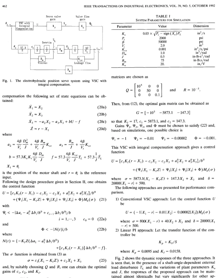
Based on the block diagram as shown in Fig. 1, by combining (17)-(19), the servo valve gain K,, and the VSC with integral
462 IEEE TRANSACTIONS ON INDUSTRIAL ELECTRONICS, VOL. 39, NO. 5, OCTOBER 1992 Servo valve Valve, f lob
gain gain
I
I n e r t i a>
Fig. 1. The electrohydraulic position servo system using VSC with integral compensation.
compensation the following set of state equations can be ob- tained:
x ,
=x2
(20a)x2
= X , X 3 = - a 2 X 2 - a , X ,+
bU - f (20c) Z = r - X , ( 2 W where 4PD
:
4~ B m B m 4PJ v ,
+
- - K c e a 2 = - - U , =-
+
- K c e V , J K J 4PDm
4P Kce 1v , J
v , J
J b = 57.3K,,Ks-- f = 57.3--TL+
57.3-TL XI = 0,is the position of the motor shaft and r = 0, is the reference input.
Following the design procedure given in Section 11, one obtains the control function
U = [ c I K , ( r - X , ) - clX2 - c 2 X 3
+
U ; X ,+
a : X 3 ] / b 0+(YiIXl - K , Z I
+
* 2 l X z l+
W3IX3I+
@)Ma(u) (21) withW l
<
-IAu, -UP
A b / b O+
c,- A b / b O l / b i = 1 , ... , 3 c0 = 0 (22a) @<
- I N ( t ) l / b (22b) and where N ( t ) = { - K 1 Z ( A a 1 - a Q A b / b O ) + [ c , K , ( r - X , ) ] A b / b O - f}.The r function is obtained from (3) as
(T c1(X1 - K , Z )
+
c 2 X 2+
X 3 ( 2 3 )and, by suitably choosing Q and R , one can obtain the optimal gains of c1, c 2 , and K , .
I v . SIMULATION RESULTS AND DISCUSSIONS The robustness of the proposed approach against large plant parameter variations and external load disturbance has been simulated for demonstration. The nominal values of the hy- draulic system parameters are listed in Table I. The weighting
TABLE I
SYSTEM PARAMETERS FOR SIMULATION
Dimension Parameter Value Ks 0.03 X dPs - sign ( X u ) PL in2/s ps P
v,
K c e D m 1.o
in'/rad J B m 75 K 20. in/V 2000 Psi 50000 PSI 2.0 in3 0.001 in3/s/psi 0.5 in-lb-s2/rad in-lb.s/radmatrices are chosen as
['I5
0i ]
and R = l o p 5 .Q =
0 500 0.1
Then, from (12), the optimal gain matrix can be obtained as G = [ - lo 5 -5873.1 - 147.31
so that K , = 17, c1 = 5873.1, and c 2 = 147.3. based on simulations, one possible choice is
Gains
Wl,
W2,W3,
and @ must be chosen to satisfy (22) and,W,
= -1 W2 = -0.01 q3 = -0.00002 @ = -0.001. This VSC with integral compensation approach gives a control functionU = [ c , K , ( r - X I ) - c , X , - c 2 X 3
+
u!X2+
a : X 3 ] / b 0 +(WlIXl - K , Z I+
W2IXzI+
W3IX3I+
@ ) M 6 ( a )where (T = 5873.1(X1 - K , Z )
+
147.3X2+
X , and 6 = The following approaches are presented for performance com-1) Conventional VSC approach: Let the control function U
20000lXl -
T I
+
500. parison.be
U = ( - lIX, - rl - 0.OllX2l - 0.000021X31)M~(~)
where U = 800(X, - r )
+
40X2+
X , and 6 = 200001X1 2) Linear PI approach: Let the transfer function of the con-- rl
+
500.troller be
K p + K , / S where K p = 0.0095 and K , = 0.0158.
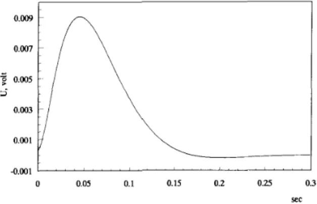
Fig. 2 shows the dynamic responses of the three approaches. It is seen that, in the presence of a shaft-angle-dependent external load disturbance TI> and the variations of plant parameters K,, and J , the responses of the proposed approach can be main- tained almost identically but vary significantly for other ap- proaches. Fig. 3 shows the waveform of the control function U.
It is clear that by using a modified proper continuous function the chattering phenomena can be effectively suppressed. Thus, the proposed approach seems amenable for practical implemen- tation.
IEEE TRANSACTIONS ON INDUSTRIAL ELECTRONICS, VOL. 39, NO. 5, OCTOBER 1992 463 0.4
1
I
'..L
I
0 0 0.05 0.1 0.15 0.2 0.25 0.3 Sec (a) 0 0.05 0.1 0.15 0.2 0.25 0.3 Sec (b) 1.2 1 0.8 0.6 0.4 0.2 0 0 0.05 0.1 0.15 0.2 0.25 0.3 Sec (C)Fig. 2. Angular responses in the presence of load disturbance T,, and variations of plant parameters K,, and J . (a) The proposed VSC with integral compensation approach. (b) The conventional VSC approach. (c) The linear PI approach.
+: normal (TL = 0, K , = 20 in/V, J = 0.5 in-lb-s*/rad) +: -50% change in K,,
+: 1000% change in J U: T~ = 5001e,i
V. CONCLUSIONS
A VSC with integral compensation for an electrohydraulic
position servo control system is presented. It has been shown that the proposed approach is theoretically robust to the plant parameter variations. It can achieve a zero steady-state error for step input and has an optimal motion with respect to a quadratic
0.009 0.007 +
7
0.005 a 0.003 0.001 -0.001' """ "" "" " '" " " '
0 0.05 0.1 0.15 0.2 0.25 0.3 SecFig. 3. Control signal of the proposed approach.
performance index. Simulations show that the proposed ap- proach can give a quite accurate servo-tracking response in the face of large plant parameter variations and external load d:;tur- bance.
REFERENCES
V. I. Utkin, "Variable structure systems with sliding modes," IEEE Trans. Automat. Contr., vol. AC-22, pp. 212-222, 1977.
U. Itkis, Control Systems of Variable Structure. New York: Wiley, 1976.
B. D. 0. Anderson and J. B. Moore, Linear Optimal Control Systems. Englewood Cliffs, NJ: Prentice-Hall, 1971.
G. Ambrosino, G. Celentaflo, and F. Garofalo, "Variable structure model reference adaptive control system," Int. J. Contr., vol. 39, pp. 1339-1349, 1984.
H. E. Merrit, Hydraulic Control System. New York: Wiley, 1967. J. S. Yun and H. S. Cho, "Adaptive model following control of
electrohydraulic velocity control systems subjected to unknown
disturbances," IEE Proc., pt. D., vol. 135, pp. 149-156, 1988.
A Rotor Time Constant Evaluation for Vector-Controlled Induction Motor Drives
Piotr J. Chrzan and Piotr Kurzyhki
Abstract-The on-line identification method of the rotor time constant of an induction machine is derived from the steady-state analysis of the machine space vectors. Simulation of the indirect field orientation system is performed to verify the method convergence in quasi-steady- state operation, independently of the initial controller parameters.
I. INTRODUCTION
Digital vector control techniques incorporating PWM invert- ers have made possible the development of high-performance induction motor drives. However, in these solutions the control gains depend heavily on the motor parameters, particularly on the rotor resistance or the rotor time constant, which change widely with temperature, frequency, and current amplitude.
Manuscript received April 11, 1992; revised June 18, 1992. The authors are with the Electrical Engineering Department, Techni- IEEE Log Number 9202535.
cal University of Gdansk, 80-952, Gdansk, Poland.