Large-Scale Interactive Walkthrough over the Web
15
0
0
全文
(2) 2. tree structures to describe object hierarchies in the models. Given a viewing information, we will be able to quickly compute which objects are visible and required by simply traversing those trees. To minimize the bandwidth requirements, only needed objects will be transmitted to clients over the network. Several related researches have been presented. In [5], they addressed an effective and efficient method of visibility precomputing. In the method, models are subdivided into rectangular cells and visibility computations are performed for those cells. The visibility computations are aimed to find the set of cells visible to an observer able to look in all directions from a position within the cell, and to find the set of objects partially or completely visible to an observer with a specified viewing cone. In [1], they perform visibility precomputations analogous to the ones in [5]. Once precomputation is done, all resulting data is loaded into a display database. Then an efficient memory management algorithm which is performed during the walkthrough phase takes responsibility for swapping objects in and out of the memory as the observer moves through the model. Their methods work well for an indoor model like a building, however, are not proper for an outdoor model like a terrain. Since in an outdoor model, not so many objects are actually occluded by other objects from the observer’s viewing cone. When expanding to Internet, it will introduce more challenges to be overcome. Nowadays Internet is getting quite mature to support architectural walkthroughs, and more and more people can visualize preconstructed models via Internet. An architect can even preview his or her creations without leaving home. Web-based walkthrough system can also be expanded to other applications. For instance, multiple users can join the same online flight simulation to fight together or with each other. In [3], they presented a mechanism that allows to visualize remote VRML scenes through low-bandwidth connections. Their system contains one application server who takes responsibility for all processes and another information server who maintains VRML scenes. After a request for a VRML scene is sent to application server, application server fetches the requested VRML files from information server through high-bandwidth connection, and subsequently sends the hierarchies of objects in the requested VRML scene back to client. Users can select the parts they are interested in, then send the results back to the application server. The application server.
(3) 3. will generate a new VRML file for the results. Users can now browser the VRML scene using their own browsers. The organization of the paper is as follows. We describe VRML briefly in Section II, and overview our system architecture in Section III. In Section IV, model preprocessing will be discussed. In Section V, we will focus on run-time environments at both server and client, respectively. Finally, in Section VI we conclude the paper and describe possible future work.. II. VRML A. The Basic VRML (Virtual Reality Modeling Language) is designed to be platform-independent, extensible, and has the ability to work on low-bandwidth connections. The VRML file format supports complete descriptions of 3D scenes with geometry, lighting, materials, 3D user interface widgets, and viewers. VRML is constructed based on Scene Graph. Hierarchy of a VRML scene is based on a tree structure. For interactivity, VRML provides a set of sensors and detectors to enable user to interact with the virtual worlds. When user enables one of them, an event is generated by a specified node and is received by its routing destination node to dynamically change part (or parts) of a virtual world to achieve interactivity. Furthermore, there is another special ”Script” node that can be programmed by JAVA language or Java Script to allow for interactivity. Apparently, it can offer a more flexible way to achieve interactivity than those sensors and detectors predefined in VRML.. B. External Authoring Interface In an external environment, External Authoring Interface (EAI) provides functionalities analogous to Script. EAI is designed to be a standard interface between a VRML world and an external environment, and is implemented only for JAVA language. It is executed within a Java Applet that is embedded in a HTML document. All operations of EAI depend on references. A reference is obtained by specifying a name that is defined in VRML using ”DEF” tag. In EAI, each procedure is based on reference of the browser, therefore,.
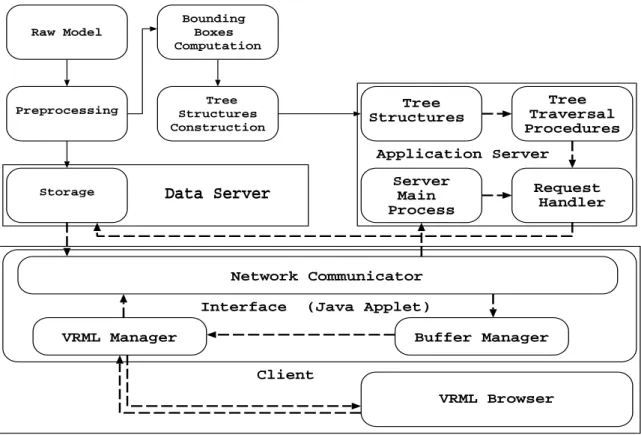
(4) 4. it has to be gained before invoking any EAI procedure. Via reference of the browser, we can gain references of nodes and references of events that are covered in the node. When we assign a value to an event by its reference, it will invoke sequential reactions to achieve interactivity. Nowadays, almost all existing VRML browsers support Script and EAI.. III. S YSTEM OVERVIEW Our system is executing in two distinct stages as shown in Figure 1. Firstly, models are preprocessed and stored in the data server. In model preprocessing stage, several tree structures are built to describe object hierarchies in the model. These tree structures will be stored in the application server. Later, we will simulate an observer walking through the model under user control with mouse and keyboard, and render the model as seen from observer’s viewpoint in each frame. While the observer walks through the model, an application program (VRML Manager), registered to monitor position and orientation of the observer, will collect all necessary information and send a request to application server via the Network Communicator. Moreover, the application server yields a process (Main Process) which takes responsibility for listening to requests. Once a request is accepted, application server will create a new thread (Request Handler) to serve it. The handler will invoke a procedure (Tree Traversal Procedure) to traverse those trees. Afterwards, the needed VRML files are retrieved from data server, transmitted to client and added into VRML world. Note that data server and application server may be on the same machine or located across different sites.. IV. M ODEL P REPROCESSING A. Tree Construction This stage emphasizes processing model raw data to generate tree structures helping to find visible objects in the interactive walkthrough stage. In constructing the tree structures, we compute the three-dimensional bounding box of every object but only use its X and Z coordinates to index the tree nodes. The results are objects differing only in Y-coordinate will be placed together in the same node. This preprocessing may take.
(5) 5. Raw Model. Bounding Boxes Computation. Preprocessing. Tree Structures Construction. Tree Structures. Tree Traversal Procedures. Application Server Storage. Server Main Process. Data Server. Request Handler. Network Communicator Interface. (Java Applet). VRML Manager. Buffer Manager Client VRML Browser. Fig. 1. System architecture. Note that solid line means preprocessing stage and dotted line means interactive walkthrough stage.. hours to finish. However, the process is automatic and performed in batch, and needs to be performed only once. The tree construction procedure is divided into two steps. 1) First Step: Quad Tree Construction: The whole model is assumed to be enclosed in a long pillar, with sides parallel to XY and YZ planes spanning the whole range of Y-axis. Each time we use two perpendicular midplanes in X-axis and Z-axis of the pillar to divide it into four equal-sized smaller pillars. Objects that intersect these two midplanes will be encapsulated in current node, and thus four smaller pillars will become four children of the current node which is root in the first subdivision. We proceed to further subdivide these four children in a recursive manner. The pillar subdivision process ceases whenever a node (i.e., a pillar) contains no objects. When each leaf has no objects in it, the whole tree construction process is complete. The resulting tree essentially is a quad tree, and it is based on MX-CIF quad tree described in [4]. However, the original MX-CIF tree was designed to represent the hierarchy of rectangles in two-dimension only, and here we expand it to three-dimensional case. Figure 2 illustrates a top view of a simple scene - a quad tree structure for it (Figure 2a), and two binary.
(6) 6. Z. X. Z xa. 2. 5. xg {14}. 3. 13. 4. za xh. {8,16}. zg. zh. {9}. 1. {10}. 6. xi 16. zj. zi. 9. {6}. xj. zl. 8. 7. {7}. 15. {2} (b). 14 11 10 12. X. xg. {14}. za. {8,16}. A{2,6,7,8,9,10,14,16} xj D{11}. C{1} B{13}. {9} {7}. zg. xh. {10} zl {2}. G{12} F{15}. E{3,4,5} (a). {6} zi. (c). Fig. 2. (a) A quad tree example; (b) its two binary trees for node A; and (c) the simplified trees of (b).. trees for the node A (Figure 2b). After the first subdivision, object 2, 6, 7, 8, 9, 10, 14, and 16 are extracted to form root (node A) because they intersect two midplanes. The root has four children, which are northwest pillar (node B), northeast pillar (node C), southwest pillar, and southeast pillar (node D), respectively. When we proceed to subdivide northeast pillar, object 1 intersects the midplanes of the northeast pillar and is selected to form node C. In the same way, object 3, 4, and 5 are extracted to form a child node of C because they intersect the midplanes of the current subdivided pillar. In the northwest pillar, the second subdivision extracts object 13 to form node B because it intersects the midplanes of the pillar. Since the northwest pillar only contains object 13, we will not subdivide them further after the object 13 is picked and added into the quad tree. For southeast pillar, object 11 is encapsulated in node D because it intersects two midplanes of this pillar. Finally, object 12 and 15, intersecting midplanes of two child pillars of node D, are encapsulated in two child nodes of D (i.e., node F and node G). The construction of two binary trees of node A will be described in next section..
(7) 7. 2) Second Step: Binary Tree Construction: Subdivision process in the first stage decomposes the model into many smaller pillars in three-dimension. The second stage is aimed to decompose them finer in each of the two spatial dimensions (X and Z). Given every partitioned plane has its own associated objects, we will construct the spatial location representation of objects in each plane using a binary tree structure. Let objectA and objectB be two object sets associated with two midplanes of the pillar (if there exists an object in both objectA and objectB, it will be assigned to objectB). In each object set, we use a midline parallel to Y-axis of the plane to divide it into two equal subplanes. Objects which intersect the midline will be selected to form the current node, becoming root in the first subdivision. And the two subplanes become children of this node. If no objects intersect this midline, the node is simply an empty node. The procedure is complete until there is no planes that contain objects. The same procedure needs to be performed twice, one for objectA and another for objectB. Basically, the rules used here are similar to the ones in previous section. According to our example, object 8 and 16 intersect both two midplanes of the pillar, they are assigned to objectB. Now objectA contains object 7, 9, and 14. ObjectB contains object 2, 6, 8, 10, and 16. In objectA, first subdivision does not produce any more useful results because there is no objects intersecting the midline. Therefore, its root is an empty node. Object 9 intersects the midline of right plane in the second subdivision, it will be assigned to right child node of the root. On the left plane, object 14 intersects the midline, it is assigned to left child node of the root. Object 7 will be added into the binary tree until it is found to intersect the midline of a plane. Similarly in objectB, object 8 and 16 are encapsulated in root in the first subdivision because they intersect midline of the plane. Object 10 intersects midline of the subsequently divided plane, it will be placed in node zg. And object 6 and 2 are added into the binary tree in the third and the fifth subdivision process (denoted as node zi and zl). At the time we constructed the binary trees, we found that trees contain several unnecessary empty nodes. It makes a tree deeper and requires more capacity to store it. Therefore, we apply two rules to simplify the tree..
(8) 8. 1) Remove all empty leaf nodes. 2) A node which is qualified to replace its parent must have only one child or itself is a leaf node. When an empty internal node N has more than one qualified child, we will choose the one which has the largest depth to replace N in order to reduce depth of the resulting tree. To simplify both trees in Figure 2b, we first apply rule one to remove all empty leaf nodes. Then we apply rule two to remove unnecessary empty internal nodes. For example, in node xa, we use node xg to replace it, and then node xi is replaced with node xj. In node zh, we use node zj to replace it, and in turn use zi to replace zj. The final results are presented in Figure 2c.. B. Object Collection In recent years, increased computing resources offer considerable benefits when quantitative modeling techniques and intensive computations are frequently used in architectural walkthrough simulations. However, the greatest impediment to developing such systems is the size of the data that constrains interactive response time. As data sizes increase, interactive control of the visualization is lost when the time to transmit, process, or render data becomes prohibitively large. It is therefore essential to subdivide the model data into many small portions and load only a small volume of data into main memory at a time. Generally, it is expensive to perform an I/O operation and to perform a network transmission. A packet consists of the header and data. Usually the length of the header is fixed, it does not change like size of the data. Opening a connection to transmit a small-sized object is therefore not feasible. We will aggregate many objects and store them into a file as long as their size does not exceed a threshold value. Since we collect many objects in a file which will be transmitted as a whole, there might be some unneeded objects in the file that will be transmitted over to client as well. Objects stored in the file are by in-order traversal. In-order traversal of the nodes usually implies a spatial locality - nearby objects are stored spatially adjacent. As a result, the number of files that need to be fetched and transmitted to client at interactive walkthrough will be smaller..
(9) 9. C. Representation After tree construction is done, the resulting trees reside in main memory. Because main memory is volatile, we have to store them as external files so that they are able to be restored later. 1) Quad Tree: To describe a quad tree and its associated nodes, we use a long character stream to represent them. Each node has a list of fields to describe itself. In it, fields are separated using specific characters. Such information contains node ID, the pillar it represents, offset to two of its binary trees, offset to its four children, and objects it encloses. 2) Binary Tree: The character stream we use to represent binary tree is similar to the one for quad tree. It consists of node ID, the midline of the plane, offset to its two child nodes, the spatial range that encloses the whole objects in the node, and the objects it encloses. 3) Object Information: Finally, there is information about the objects that needs to be stored. It should include ID of the object, bounding box information in the three-dimension, file name where object is stored, and object index in the file storing it.. V. I NTERACTIVE WALKTHROUGH At this stage, we provide a simulation environment for an observer to walk through the architectural models under user control. The primary goal of this stage is to render the models as smoothly as possible without any disturbance. However, most models are so large that they cannot be 1) completely loaded into memory; 2) rendered at interactive frame rates; 3) quickly transmitted over the network. Thus we must identify a small portion of objects depending on the position and viewing area of the observer to cull away other invisible parts. As the observer moves, our interface program (written in JAVA Applet) will send the information to application server, making application server perform tree traversal depending on the information from client. The results will notify the data server to fetch and transmit target VRML files to client..
(10) 10. A. Interface (Client Side) Our interface program is stored at application server, downloaded and executed by client when a session is established. The interface takes responsibility for coordinating all functionalities at client side. In it, there are three major components, which are Network Communicator, Buffer Manager, and VRML Manager. 1) Network Communicator:. As the name shows, it takes responsibility for all client’s network. communication such as sending requests to and receiving VRML files from data server. When update is needed, it will send necessary information to application server. However, it is not feasible to update so frequently. Therefore, we have to decide on an effective update mechanism. Our considered parameter is the frame rate. When frame rates are too low, the observer cannot walk through the model smoothly. If we update the VRML world at a higher rate, the observer may miss the sight of some objects in the VRML world. In our system, we define a lower and a upper threshold to adjust the update frequency so as to make it proportional to frame rates. When the current frame rate exceeds the upper threshold, the update frequency will increase. On the contrary, update frequency will decrease when the current frame rate is less than the lower threshold. Network Communicator also informs data server the objects that are maintained at client to avoid transmitting duplicated files. That is, it only has to focus on the files that need to be transmitted to client and that are not maintained at client side. It will alleviate transmission load significantly. 2) Buffer Manager: Due to the bandwidth limitation and large data size, it is difficult to transmit objects over the Web without significant latencies. A buffer is therefore needed. A buffer with high hit-rates can reduce transmission times significantly. Every time new objects are brought into the buffer, we may need to find candidates to be replaced by these new objects when there is no more space in the buffer to accommodate new ones. Selecting candidates for replacement is very important and that is what the Buffer Manager is responsible for. The method we used to determine candidates for replacement is basically the same as LRU (Least Recently Used) policy..
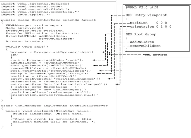
(11) 11. 3) VRML Manager: The VRML Manager not only monitors position and orientation of the observer, but also adds objects dynamically into the VRML world. Each scene update initiates at VRML Manager which is programmed in EAI [2]. The manager is registered to monitor position and orientation of the observer. Once he or she moves, the manager can be aware of that and receive new spatial location of the observer. The example code in Figure 3 illustrates how to register to monitor the position and orientation of the observer at VRML Manager. To monitor the observer, we must obtain reference of the browser which each operation depends on. Subsequently we use it to obtain references of ”Viewpoint” node, and field references of ”position” and ”orientation”. We will invoke advise() method to register an instance of a class ”VRML Manager” which implements the interface ”EventOutObserver” to achieve this. This class must implement a method named ”callback” to handle events. Once the monitored events are triggered, the ”callback” method will be invoked, its parameter contains source event and the time stamp. After capturing all necessary information, we will evaluate if the update is needed depending on the update mechanism we use. Another operation which is performed by the VRML Manager is to add objects into the VRML world. To this end, we create an empty VRML world with a simple background containing an empty ”Group” node. In the node, there is an EventIn named ”addChildren”. References to both ”Group” node and ”addChildren” EventIn are needed in order to add objects into the VRML world by invoking a method named ”setValue()”, in which its parameter represents the objects we want to add into the VRML world. Contrasting with ”addChildren”, there is another EventIn named ”removeChildren”. Removing objects from VRML world is achieved by its reference too.. B. Application Server As shown in Figure 1, our application server consists of three main components, which are Server Main Process, Request Handler, and Tree Traversal Procedure. 1) Main Process and Request Handler: The Main Process is a socket-based program that listens to all requests and creates a new thread to handle each request. This new created thread is what we called Request.
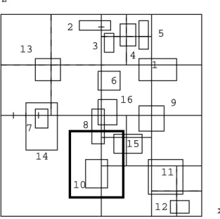
(12) 12. import import import import import. vrml.external.Browser; vrml.external.Node; vrml.external.field.*; vrml.external.exception.*; java.applet.*;. public class OurInterface extends { VRMLManager vrmlmanager; Node entry,root; EventOutSFVec3f position; EventOutSFRotation orientation; EventInMFNode addChildren, removeChildren; Browser borwser;. #VRML V2.0 utf8. Applet. public void init() { browser = Browser.getBrowser(this); try { root = browser.getNode("root"); addChildren = (EventInMFNode) root.getEventIn("addChildren"); removeChildren = (EventInMFNode) root.getEventIn("removeChildren"); entry = borwser.getNode("Entry"); position = (EventOutSFVec3f) entry.getEventOut("position_changed"); orientation = (EventOutSFRotation) entry.getEventOut("orientation_changed"); } catch( some Exceptions ) {} vrmlmanager = new VRMLManager(); position.adivse(vrmlmanager.null); orientation.advise(vrmlmanager,null); }. DEF Entry Viewpoint { position 0 0 0 orientation 0 1 0 0 } DEF Root Group { addChildren removeChildren } VRML browser. } class VRMLManager implements EventOutObserver { public void callback(EventOut value, double timestamp, Object data) { /*Once an event is generated, this callback method will be invoked. */ } }. Fig. 3. Example code for registration to monitor the observer.. Handler. It will invoke Tree Traversal Procedure to find target objects in the viewing area. The results will be sent to data server for retrieval. 2) Quad Tree Traversal: Given a pillar P representing the viewing volume of the observer, we use P to exemplify the tree traversal process. The idea behind the tree traversal is to find objects which intersect P. In the quad tree traversal, we compute whether P intersects the pillar represented by a node. When it does, we continue traversing its binary trees or its children. Otherwise, we stop traversing its descendents further. In Figure 4, the bold rectangle denotes the viewing volume of the observer in two-dimension. Because the viewing volume intersects root of the quad tree (see Figure 2a), we need to traverse root’s binary trees and its three children. In its three child nodes, only one child node (node D) intersects P, and only one of D’s children (node F) intersects P. Therefore in the whole model, only objects which are covered in those three nodes will be computed and found in the tree traversal..
(13) 13. z 2. 5 3. 13. 4 1 6 16. 9. 8. 7. 15 14 11 10 12. x. Fig. 4. An example demonstrating the tree traversal.. 3) Binary Tree Traversal: In the binary trees, each node maintains a midline and the range enclosing the objects. The midline is used to decide which children are to be traversed. When P covers both sides of the midline, both children need to be traversed. When P covers only one side of the midline, only one of its two children has to be traversed. The range enclosing objects is used to decide if we need to compute objects in the node or not. When P covers both sides of the midline, it absolutely overlaps some objects in the node. When it only covers one side of the midline, it is still possible that P overlaps some objects in the node. Take the object 8 for example, it is maintained in the root of a binary tree of node A. You can find out that P only covers one side of midline, but it still intersects object 8. Earlier by the example in previous section, we realize that only three nodes in quad tree need to be traversed. They are node A, node D, and node F. Node D and node F only contain one object. By simple computing, we find that only object 15 intersects P. In node A, only object 8 and 10 are overlapped by P after the binary trees of node A are searched. Object 8 is located in the root of the binary tree, it will be computed and found immediately. After the first comparison, the process proceeds to traverse the left child node of root, thus object 10 is found to be overlapped by P..
(14) 14. 4) Tree Traversal Process: The tree traversal consists of two parts which are quad tree traversal and binary tree traversal. When tree traversal begins, a primary thread takes responsibility for traversing the quad tree. If it finds a pillar (associated with a node) intersects P (the viewing volume), it will put the node into a specific queue. There are several threads which are supported to traverse the binary trees of a node in the queue. Those threads work concurrently. When a thread finishes the job, it will check if there are remaining jobs in the queue. If the queue is not empty, the thread will take a job from the queue and process it or it will wait until any job request is coming. After a thread finishes the service, it will send the results to data server immediately.. C. Discussion The two greatest challenges of our system are the tree traversal and network transmission. Since tree traversal performs concurrently, there is a room for speed-up. Because models are subdivided into many small objects, which are stored into a file as long as the total file size not exceeding a threshold. Consequently size of each file is roughly identical, and each one can be transmitted over the Internet more rapidly. Furthermore, a cached buffer is maintained at client to store objects that have been accessed recently, and those objects are very likely to be seen by the observer again in the near future. Therefore, the number of files which need to be transmitted may decrease significantly.. VI. C ONCLUSION. AND. F UTURE W ORK. We have presented an environment for visualization of large-scale VRML models over the Web. In our system, we preprocess models and build tree structures so as to speed up run-time performance in interactive walkthroughs. In it, application server performs tree traversal during interactive walkthrough to extract objects visible to the observer. Only portions of objects will be rendered in each frame to achieve better frame rates. Our current system can not handle texture yet. We will add the functionalities for texture in the near future to make models look more realistic. Besides, several compression techniques will be explored to speed up.
(15) 15. the network transmission.. R EFERENCES [1] T. A. Funkhouser, C. H. Sequin, and S. J. Teller. Management of. L arge A mounts of D ata in I nteractive B uilding W alkthroughs.. ACM. SIGGRAPH Special Issue on Interactive 3D Graphics, pages 11–20, 1992. [2] C. Marrin. Proposal for a VRML 2.0 I nformative A nnex ( E xternal A uthoring I nterface R eference). Silicon Graphics, Inc, November 1997. [3] A. B. Raposo, L. P. Magalheas, and I. L. M. Ricarte. Working with. R emote VRML S cenes through L ow- B andwidth C onnections.. X. SIBGRAPI’97 - Brazilian Symposium of Computer Graphics and Image Processing, October 1997. [4] H. Samet. The Design and Analysis of Spatial Data Structures. Addison-Wesley, MA, 1990. [5] S. J. Teller and C. H. Sequin. Visibility P reprocessing for I nteractive W alkthroughs. Proceedings of SIGGRAPH’91, In Computer Graphics 25(4):61–69, August 1991..
(16)
數據
相關文件
Interestingly, the periodicity in the intercept and alpha parameter of our two-stage or five-stage PGARCH(1,1) DGPs does not seem to have any special impacts on the model
We showed that the BCDM is a unifying model in that conceptual instances could be mapped into instances of five existing bitemporal representational data models: a first normal
The syntax analyzer takes a source text file and attempts to match it on the language grammar. If successful, it can generate a parse tree in some structured
Now, nearly all of the current flows through wire S since it has a much lower resistance than the light bulb. The light bulb does not glow because the current flowing through it
Students were required to compare in the formulation stage as the case teacher asked them to look at additional mathematical relationships, whilst they were required to compare in
O.K., let’s study chiral phase transition. Quark
• Formation of massive primordial stars as origin of objects in the early universe. • Supernova explosions might be visible to the most
This kind of algorithm has also been a powerful tool for solving many other optimization problems, including symmetric cone complementarity problems [15, 16, 20–22], symmetric
